Garmin G1000 Maintenance Manual
Columbia 350/400
Hide thumbs
Also See for G1000:
- Manual (724 pages) ,
- Pilot's manual (708 pages) ,
- System maintenance manual (340 pages)

Related Manuals for Garmin G1000


Summary of Contents for Garmin G1000
- Page 1 G1000 System Maintenance Manual Columbia 350/400 190-00577-03 October 2007 Revision C...
- Page 3 Garmin. Garmin hereby grants permission to download a single copy of this manual and of any revision to this manual onto a hard drive or other electronic storage medium to be viewed and...
- Page 4 Section 3 3-1 thru 3-12 Section 4 4-1 thru 4-82 Section 5 5-1 thru 5-12 Section 6 6-1 thru 6-118 Section 7 7-1 thru 7-2 Section 8 8-1 thru 8-2 Page B G1000-Columbia 350/400 System Maintenance Manual Revision C 190-00577-03...
- Page 5 CAUTION All G1000 screen shots used in this document are current at the time of publication. Screen shots are intended to provide visual reference only. All information depicted in screen shots, including software file names, versions and part numbers, is subject to change and may not be up to date.
- Page 6 This Page Intentionally Left Blank Page G1000-Columbia 350/400 System Maintenance Manual Revision C 190-00577-03...
-
Page 7: Table Of Contents
Shield Block Installation.....................2-10 G1000 System Communications....................2-12 2.3.1 Flight Instrumentation ......................2-12 2.3.2 Engine Indicator System....................2-14 2.3.3 Communications/Navigation Systems................2-15 G1000 CONTROL AND OPERATION .....................3-1 User Interface..........................3-2 3.1.1 Flight Management System (FMS) Knob ................3-2 3.1.2 Softkeys ..........................3-2 3.1.3 AFCS Controls........................3-3 G1000 Normal Mode ........................3-4 Reversionary Mode ........................3-5... - Page 8 Configuration Pages ......................4-70 4.12.2 GFC 700 Pre-Flight Test Sequence and Troubleshooting ..........4-72 4.13 Backshell Connectors........................4-79 G1000 EQUIPMENT REMOVAL AND REPLACEMENT..............5-1 GDU 1040 PFD/GDU 1042 MFD ....................5-2 GMA 1347 Audio Panel.........................5-2 GIA 63 Integrated Avionics Units ....................5-2 GEA 71 Engine/Airframe Unit .......................5-3 GTX 33 Transponder........................5-3...
- Page 9 5.17 GSM Slip Clutch Adjustment Procedure ..................5-7 5.18 Configuration Module Removal and Replacement ...............5-8 5.19 GEA 71 Backshell Thermocouple Removal and Replacement...........5-10 G1000 EQUIPMENT CONFIGURATION AND TESTING..............6-1 GDU 1040 PFD/GDU 1042 MFD ....................6-1 6.1.1 PFD/MFD Software Loading using GDU V6.XX ..............6-1 6.1.2...
- Page 10 WX-500 Stormscope using GDU V8.XX .................6-108 6.12.8 Ryan 9900BX TCAD Configuration using GDU V6.XX ...........6-109 6.12.9 Ryan 9900BX TCAD Configuration using GDU V8.XX ...........6-111 6.13 Complete G1000 software load using GDU V8.XX..............6-112 6.14 Software/Configuration Troubleshooting...................6-116 6.14.1 System Communication Hierarchy ..................6-117 SYSTEM RETURN TO SERVICE PROCEDURE................7-1 GIA Failure Test ..........................7-1...
- Page 11 Figure 3-6. Normal Mode ..........................3-4 Figure 3-7. MFD Failure Mode ........................3-5 Figure 3-8. PFD Failure Mode........................3-5 Figure 3-9. G1000 LRU Configuration File Storage ..................3-8 Figure 3-10. GRS/GDC Configuration Settings Storage................3-9 Figure 3-11. SET>ACTV Diagram......................3-10 Figure 3-12. Loss of Communication ......................3-11 Figure 3-13.
- Page 12 Figure 5-2. Configuration Module Installation ...................5-8 Figure 5-3. GEA Backshell Thermocouple....................5-10 Figure 6-1. G1000 Normal Mode Check ....................6-7 Figure 6-2. G1000 Reversionary Mode Check..................6-7 Figure 6-3. Marker Beacon Symbology....................6-14 Figure 6-4. GPS Signal Status ........................6-23 Figure 6-5. Aileron and Elevator Trim Calibration ...................6-39 Figure 6-6.
-
Page 13: Introduction
Use the information presented in the manual in conjunction with required documents shown in Table 1-1. 1.1.1 Applicability This document applies to all 350/400 aircraft equipped with the G1000 Integrated Cockpit Avionics Suite installed. 1.2 Organization The following outline briefly describes the organization of this manual:... -
Page 14: Definitions/Abbreviations
S/W: Software Type Certificate TSO: Technical Standard Order TVS: Transient Voltage Suppressor VHF: Very High Frequency 1.3.1 Units of Measure Unless otherwise stated, all units of measure are English units. Page 1-2 G1000-Columbia 350/400 System Maintenance Manual Revision C 190-00577-03... -
Page 15: Reference Publications
Table 1-1. Required Documents Document Part Number Vendor G1000/350/400 Required Equipment List RB011002 CAM (Columbia Aircraft Manufacturing) G1000 Cockpit Reference Guide for the Columbia 350/400 190-00567-00 Garmin G1000 Cockpit Reference Guide for the Columbia 350/400 190-00567-01 Garmin (updated for GDU V8.XX software) RB050005 Columbia 350 (G1000) Pilot’s Operating Handbook and... -
Page 16: Distribution
[1] Columbia Aircraft Manufacturing P/N 1.5 Distribution This document is to be a permanent aircraft record and is distributed with a new G1000-equipped Columbia 350/400 aircraft. Revisions to this document will be made by Garmin and will be distributed by Garmin per standard documentation revision procedures. -
Page 17: System Description
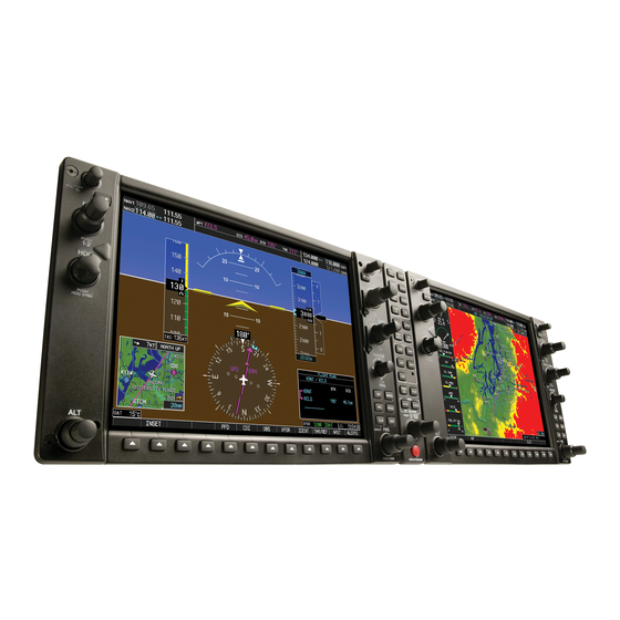
Figure 2-1. G1000/350/400 Display Configuration Two Garmin GDUs are installed in the 350/400 instrument panel. The PFD is a GDU 1040 and the MFD is a GDU 1042. Both displays provide control and display of nearly all functions of the G1000 integrated cockpit system. -
Page 18: Gia 63 Integrated Avionics Unit
Garmin GFC 700 autopilot. GIAs provide communication interface to all other G1000 LRUs in the system. Both GIAs are located directly behind the MFD, installed into their respective LRU racks. The #1 GIA is powered through the essential bus and immediately powers up when the left battery or right battery master switch is turned on. -
Page 19: Gtx 33 Mode S Transponder
The Garmin GTX 33 provides Mode A, C, and S altitude and position reporting information from the G1000 system. The unit is mounted directly behind the PFD in its LRU rack. Power is received from the Avionics Bus. The GTX 33 sends data via RS-232 directly to a GIA 63. Information is then sent to the PFD, where the pilot can control the transponder. -
Page 20: Gdc 74A Digital Air Computer
Figure 2-5. GDC 74A Air Data Computer The Garmin GDC 74A provides digital air data to the G1000 system. The unit is mounted to its rack directly behind the PFD. Power is received from the Essential Bus. The GDC 74A connects to existing pitot/static ports. -
Page 21: Gmu 44 Magnetometer
(GSM 85) without the need to de-rig the aircraft control cables. The roll servo is located beneath the rear passenger seats, and the pitch servo is located beneath the aft baggage area. G1000-Columbia 350/400 System Maintenance Manual Page 2-5 190-00577-03... -
Page 22: Gta 82 Trim Adapter
Figure 2-9. GTA 82 Pitch Trim Adapter The Garmin GTA 82 Trim Adapter is a remote mounted device that is used to allow the GFC 700 to drive a pitch trim actuator provided by the airframe manufacturer. The GTA 82 adapter is located under the instrument panel on the pilot side beneath the standby instruments. -
Page 23: Gfc 700 Afcs Operational Description
Manual Electric Trim Flight Director: The Flight Director operates within the #1 GIA 63 and uses data from the G1000 system, including air data, attitude, and navigation data, to calculate commands for display to the pilot and for the Autopilot. -
Page 24: Electrical Installation
2.2 Electrical Installation 2.2.1 Power Distribution Distribution of power to the G1000 system occurs on four aircraft electrical buses. See Figure 2-11 for diagram. Left Bus: The left bus is tied directly to the aircraft left battery (battery 1) via the left battery master switch. -
Page 25: Figure 2-11. Power Distribution
Figure 2-11. Power Distribution G1000-Columbia 350/400 System Maintenance Manual Page 2-9 190-00577-03 Revision C... -
Page 26: Wiring
350/400 electrical manual. 2.2.3 Shield Block Installation Most G1000 connectors employ a shield block grounding system to provide necessary ground reference to shielding and/or transducers. Figure 2-12. Shield Block Installation to Backshell (78-pin Connector Example) -
Page 27: Table 2-1. Parts Needed For Shield Block Installation
Table 2-1. Parts Needed for Shield Block Installation Figure Ref Description GPN or MIL spec Cast Housing (from Garmin Backshell Kit) 125-0008x-00 117-00147-00 Shield Block(s) 117-00147-01 Screw,4-40x.250,FLHP 100,SS/P,Nylon 211-63234-08 (from Garmin Shield Block Kit) Multiple Conductor Shielded Cable Reference Installation (2 –conductor demonstrated here) -
Page 28: G1000 System Communications
The GRS 77 AHRS, GDC 74A Air Data Computer, and GMU 44 Magnetometer are responsible for providing the G1000 system with flight instrumentation (refer to Figure 2-14). Data consists of aircraft attitude, heading, altitude, airspeed, vertical speed, and outside air temperature information, all displayed on the PFD (data is displayed on the MFD in reversionary mode only). -
Page 29: Figure 2-14. Flight Instrumentation Interface
No. 1 GIA 63 GRS 77 No. 2 GIA 63 Integrated AHRS Integrated Avionics Unit Avionics Unit Attitude Rate of Turn Slip/Skid Output Output GMU 44 Magnetometer Heading Figure 2-14. Flight Instrumentation Interface G1000-Columbia 350/400 System Maintenance Manual Page 2-13 190-00577-03 Revision C... -
Page 30: Engine Indicator System
2.3.2 Engine Indicator System The GEA 71 provides engine/airframe data to the G1000 system. The unit interfaces to transducers shown in Figure 2-15. Analog data is received from the transducers and is converted to a digital signal by the GEA 71. Digital information is then sent through the primary RS-485 serial path to the #1 GIA 63. -
Page 31: Communications/Navigation Systems
Various I/O Processors Digital COM/NAV Audio Digital COM/NAV Audio Voice Alerts Voice Alerts GTX 33 Mode S Course/Heading Datum Transponder To Autopilot Selected Altitude HSI Output Signals Figure 2-16. G1000 Navigation/Communications G1000-Columbia 350/400 System Maintenance Manual Page 2-15 190-00577-03 Revision C... - Page 32 This Page Intentionally Left Blank Page 2-16 G1000-Columbia 350/400 System Maintenance Manual Revision C 190-00577-03...
-
Page 33: G1000 Control And Operation
3 G1000 CONTROL AND OPERATION All control and operation of G1000 equipment as normally used in flight occurs through the PFD, MFD, GCU 476 Remote Keypad and GMA 1347 audio panel. Figure 3-1 identifies various GDU 1040/1042 buttons. Figure 3-2 identifies the GCU 476 buttons. Figure 3-3 identifies various GMA 1347 buttons. -
Page 34: User Interface
Figure 3-3. GMA 1347 Controls 3.1 User Interface 3.1.1 Flight Management System (FMS) Knob The FMS knob is the primary control for the G1000 system. Operation is similar to the Garmin 400/500 Series units. • To cycle through different configuration screens: To change page groups: Rotate the large FMS knob. -
Page 35: Afcs Controls
3.1.3 AFCS Controls The dedicated AFCS controls on the GDU 1042 are discussed in detail in the G1000 Cockpit Reference Guide for the Columbia 350/400, P/N 190-00567-00. The following figure is provided for reference. Autopilot Key Heading Mode Key Flight Director Key... -
Page 36: G1000 Normal Mode
GSA 81 Pitch and Roll Servos The G1000 system is now powered in the normal mode. The PFD and MFD will function as specified in the G1000 Cockpit Reference Guide for the Columbia 350/400 when the system has been correctly installed and configured. -
Page 37: Reversionary Mode
3.3 Reversionary Mode Should a display communication or hardware failure occur, the G1000 system automatically enters the reversionary mode. The system reversionary mode forces the remaining display into showing all information related to safe flight. A manual reversionary mode also allows the operator to force the system into reversionary mode in situations where the system does not automatically enter reversionary mode. -
Page 38: Configuration Mode Overview
3.4.1 Loader Card Interface The G1000 Code Loader Card interface exists to provide a means of loading software and configuration files to the system and LRUs. The G1000-Columbia 350/400 Code Loader Cards use a 128 MB Secure Digital (SD) data card that contains: •... -
Page 39: Configuration Files
A G1000-Columbia 350/400 Code Loader Card typically contains the following configuration files: • AIRFRAME: This file contains data such as airspeed parameters, engine/airframe sensor limitations, fuel tank parameters and alerting system settings that tailor a G1000 PFD or MFD to the 350/400. •... -
Page 40: Figure 3-9. G1000 Lru Configuration File Storage
The GEA 71 uses PFD internal configuration files for backup. GCU 476 Contains ‘ACTIVE’ configuration settings internally. GCU 476 uses PFD internal configuration files for backup. Figure 3-9. G1000 LRU Configuration File Storage Page 3-8 G1000-Columbia 350/400 System Maintenance Manual Revision C 190-00577-03... -
Page 41: Set>Actv Interface
SET items. WARNING THE ACTV>SET SOFTKEY MUST BE USED WITH CAUTION! IF AN IMPROPERLY CONFIGURED UNIT IS INSTALLED, THIS SOFTKEY CAUSES THE WRONG CONFIGURATION TO REPLACE THE CORRECT AIRCRAFT CONFIGURATION! G1000-Columbia 350/400 System Maintenance Manual Page 3-9 190-00577-03 Revision C... -
Page 42: Figure 3-11. Set>Actv Diagram
≠ ≠ SET>ACTV Softkey Master Configuration Module LRU Memory Master Configuration Module LRU Memory Configuration Correct Master Configuration Module LRU Memory Master Configuration Module LRU Memory Figure 3-11. SET>ACTV Diagram Page 3-10 G1000-Columbia 350/400 System Maintenance Manual Revision C 190-00577-03... -
Page 43: Configuration Prompts
Certain problems can be resolved simply by pressing the SET>ACTV softkey, which reloads settings to the specific LRU from the PFD. (Note that this can also be accomplished by reloading the configuration files for the LRU, using the appropriate G1000-Columbia 350/400 Code Loader Card. Section 6 describes this method for each LRU). -
Page 44: Configuration Mode Navigation
Using the FMS knob as described in Section 3.1.1 a user can navigate through different pages and page groups in the Configuration Mode. For complete description and breakdown of each page, refer to the G1000 Configuration manual, Garmin part number 190-00303-04. The following diagram shows the layout and organization of Configuration Mode page groups and pages. -
Page 45: Troubleshooting
Troubleshoot the G1000 system by first identifying, then isolating the specific failure to the responsible LRU. There are several indications that the G1000 presents to the pilot or technician, showing overall system condition. A course of action should be determined based on the information presented on the display. -
Page 46: G1000 Alerting System
Softkey Annunciation: When the G1000 Alerting System issues an alert, the ALERTS softkey is used as a flashing annunciation to accompany the alert. During the alert, the ALERTS softkey assumes a new label consistent with the alert level (WARNING, CAUTION, or ADVISORY). Pressing the softkey annunciation acknowledges the presence of the alert and returns the softkey to its previous ALERTS label. -
Page 47: Figure 4-3. Warning Softkey Annunciation
The G1000 Alert System uses three levels: WARNING Annunciation: This level of alert requires immediate pilot attention. A warning alert is accompanied by an annunciation in the Annunciation Window. Warning alert text appearing in the Annunciation Window is RED. A warning alert is also accompanied by a flashing WARNING softkey annunciation, as shown in Figure 4-3, along with a continuous aural tone. -
Page 48: System Annunciations
GDC 74A ADC Figure 4-6. System Annunciations The GFC 700 AFCS Annunciation field is located above the airspeed tape on the PFD as shown: Figure 4-7. AFCS Annunciation Field Page 4-4 G1000-Columbia 350/400 System Maintenance Manual Revision C 190-00577-03... -
Page 49: Figure 4-8. Taws Annunciation Field
GIA1 or MFD and GIA2 for faults. • Switch GIA1 and GIA2, to verify location of problem: If problem follows the GIA, replace the GIA. If problem persists, replace the MFD or PFD. G1000-Columbia 350/400 System Maintenance Manual Page 4-5 190-00577-03 Revision C... - Page 50 Check GDC configuration module wiring for damage, replace if any is found. GTP 59 • Replace GDC configuration module. • Replace GDC 74A with a known good unit: If problem persists, replace the GTP 59. Page 4-6 G1000-Columbia 350/400 System Maintenance Manual Revision C 190-00577-03...
- Page 51 If problem persists replace GRS 77 configuration module. See Section 3.4 for configuration instructions. • Contact Garmin Aviation Product Support if condition continues after replacing the GRS 77 and configuration module for additional assistance. G1000-Columbia 350/400 System Maintenance Manual Page 4-7...
- Page 52 Recalibrate the GMU 44, see section 6.7.4. • Load configuration files to the PFD, MFD, GIA1, and GIA2 If problem persists replace the GMU 44. If problem persists, replace the GRS 77. Page 4-8 G1000-Columbia 350/400 System Maintenance Manual Revision C 190-00577-03...
- Page 53 If problem persists, replace the GEA 71. • For only Red-X of the EGT, TIT and CHT temperature readings, replace the GEA configuration module and back shell thermocouple. If problem persists, replace the GEA 71. G1000-Columbia 350/400 System Maintenance Manual Page 4-9 190-00577-03 Revision C...
- Page 54 Check fuel quantity sensor – GEA wiring. Refer to latest revision of the 350/400 electrical manual. Fuel Quantity Sensors • Replace fuel quantity sensor. Refer to the 350/400 (2 per side) AMM. • Replace GEA 71. Page 4-10 G1000-Columbia 350/400 System Maintenance Manual Revision C 190-00577-03...
- Page 55 350/400 electrical manual. Current • Replace current sensor. Refer to 350/400 AMM. Shunt • Replace GEA 71. • Check bus voltage – GEA wiring • Replace GEA 71. Voltage G1000-Columbia 350/400 System Maintenance Manual Page 4-11 190-00577-03 Revision C...
-
Page 56: Afcs System Troubleshooting
GFC 700, the pilot and technician should first evaluate the overall status and condition of the G1000 system on the AUX – System Status page (on the MFD). Any alert messages, annunciations, or other abnormal behaviors should be noted in an effort to pinpoint the fault. More detailed system troubleshooting for a red AFCS or red PFT annunciation is contained in this section. - Page 57 Annunciation Condition Solutions • Ensure that the G1000 system is in proper working order. Check specifically for proper operation of the: GIA 63 Integrated Avionics Unit GRS 77 AHRS (it must align before this annunciation will disappear and allow the PFT to...
-
Page 58: Columbia 350/400 Specific Alerts
Refer to latest revision of the 350/400 electrical manual. OIL PRES Low oil pressure. • Troubleshoot according to the 350/400 AMM. • Replace oil pressure switch. • Replace GEA 71. Page 4-14 G1000-Columbia 350/400 System Maintenance Manual Revision C 190-00577-03... - Page 59 OXYGEN altitude is greater than 12000 feet. • Ensure oxygen quantity is greater than 250 psi. • OXYGEN QTY Low oxygen quantity. Troubleshoot oxygen system according to the 350/400 AMM. G1000-Columbia 350/400 System Maintenance Manual Page 4-15 190-00577-03 Revision C...
- Page 60 Check rudder hold wiring to the GEA 71. (400 Only) • Replace GEA 71. • Reminder to turn oxygen Ensure oxygen system is off. OXYGEN ON off when on the ground. Page 4-16 G1000-Columbia 350/400 System Maintenance Manual Revision C 190-00577-03...
- Page 61 328 cooling fan in avionics bay. • Troubleshoot according to the 350/400 AMM. • Replace fan in avionics bay. • Replace No. 1 or No. 2 GIA 63. G1000-Columbia 350/400 System Maintenance Manual Page 4-17 190-00577-03 Revision C...
- Page 62 350/400 electrical manual. VAPOR SUPPR (400 Only) • Replace vapor suppression switch. • Replace GIA 63. Timer has counted down to • TIMER ZERO Reset timer if desired. zero. Page 4-18 G1000-Columbia 350/400 System Maintenance Manual Revision C 190-00577-03...
-
Page 63: Gdu 1040/1042 Troubleshooting
4.4 GDU 1040/1042 Troubleshooting NOTE Garmin recommends the use of SanDisk or Toshiba SD cards to load G1000 software and configuration files. If another brand of card is used, and software loading problems occur, replace the card with a SanDisk or Toshiba card and reattempt the software load. - Page 64 Cards is not recommended. • If card was inserted with the label facing to the right, do not attempt to remove. Return the unit to Garmin for repair. • A button/knob/joystick does Go to the GDU TEST page in configuration mode and verify...
-
Page 65: Failed Path Messages (Gdu Software Version 7.01 And Later Only)
GDU’s, GIA’s or other units to determine if the fault lies in the unit or wiring. Garmin recommends following the troubleshooting instructions for the red data boxes below to help find the cause of the fault. - Page 66 PFD. Replace original PFD if box turns green after swapping displays. Replace GDC 74A if problem remains. PFD1/GDC 74 data path functionality is unknown. Reload PFD (BLK) configuration file. Page 4-22 G1000-Columbia 350/400 System Maintenance Manual Revision C 190-00577-03...
- Page 67 MFD. Replace original MFD if box turns green after swapping displays. Replace GDC 74A if problem remains. MFD1/GDC 74 data path functionality is unknown. Reload (BLK) MFD configuration file. G1000-Columbia 350/400 System Maintenance Manual Page 4-23 190-00577-03 Revision C...
-
Page 68: Database And Software Alerts
The MFD has encountered ChartView database error exists. an error in the ChartView database. PFD1 DB ERR – MFD1 The PFD has encountered an ChartView database error exists. error in the ChartView database. Page 4-24 G1000-Columbia 350/400 System Maintenance Manual Revision C 190-00577-03... - Page 69 Message Cause Solutions • DB MISMATCH – Aviation The G1000 has found the Load current Jeppesen database to both database version mismatch. Jeppesen aviation database displays. Xtalk is off. in the PFD and MFD do not match. • DB MISMATCH – Aviation...
- Page 70 Aviation Database and other optional features (i.e. TAWS unlock card) will need to be replaced if the master configuration module is changed. The G1000 System ID number will change to a new number when installing a new master configuration module. The old Terrain and other cards will no longer work as they will remain locked to the old System ID number.
-
Page 71: Gdu Cooling Alerts
(if applicable). Replace cooling fan if unable to determine if operating correctly. If problem persists, replace the PFD. • If problem continues contact Garmin Aviation Product Support for assistance. G1000-Columbia 350/400 System Maintenance Manual Page 4-27 190-00577-03 Revision C... -
Page 72: Key Alerts
Message Cause Solutions • MFD1 “key” KEYSTK – key is The G1000 has determined a Go to the GDU TEST page in stuck. key is stuck on MFD1. configuration mode and verify key is stuck (if key is stuck the corresponding PFD1 “key”... - Page 73 CCFT level rises. If the CCFT level rises, disregard the message. If the CCFT level does not rise, replace the MFD. • Replace the MFD. G1000-Columbia 350/400 System Maintenance Manual Page 4-29 190-00577-03 Revision C...
- Page 74 Aviation Database and other optional features (i.e. TAWS unlock card) will need to be replaced if the master configuration module is changed. The G1000 System ID number will change to a new number when installing a new master configuration module. The old Terrain and other cards will no longer work as they will remain locked to the old System ID number.
- Page 75 Aviation Database and other optional features (i.e. TAWS unlock card) will need to be replaced if the master configuration module is changed. The G1000 System ID number will change to a new number when installing a new master configuration module. The old Terrain and other cards will no longer work as they will remain locked to the old System ID number.
- Page 76 Aviation Database and other optional features (i.e. TAWS unlock card) will need to be replaced if the master configuration module is changed. The G1000 System ID number will change to a new number when installing a new master configuration module. The old Terrain and other cards will no longer work as they will remain locked to the old System ID number.
- Page 77 CO DET FAIL – The carbon The G1000 and CO • Check GIA/CO Guardian interconnect. monoxide detector is Guardian are not • Replace the CO Guardian. inoperative. communicating. • Contact Garmin Product Support for Assistance. G1000-Columbia 350/400 System Maintenance Manual Page 4-33 190-00577-03 Revision C...
-
Page 78: Gma 1347
THRESHOLD VALUE: Sets the Master Avionics Squelch (MASQ™) threshold value. Value is adjustable between –31 and 31. MARKER BEACON HI/LO SENSE THRESHOLD: Sets Hi/Lo marker sensitivity thresholds, value is adjustable between –31 and 31. Page 4-34 G1000-Columbia 350/400 System Maintenance Manual Revision C 190-00577-03... - Page 79 DISABLE SPLIT COM: Allows split-COM feature to be disabled for installations where split-COM operation is not desired. COM 2 ON-SIDE: In a dual audio panel installation, this designates the unit as a ‘right-hand/co-pilot’ unit. G1000-Columbia 350/400 System Maintenance Manual Page 4-35 190-00577-03 Revision C...
-
Page 80: Common Problems
If the volume is not sufficient, replace aircraft cabin speaker, reference the Airframe Maintenance Manual. • Mic Audio Heard in Speaker Reduce ICS Volume. Page 4-36 G1000-Columbia 350/400 System Maintenance Manual Revision C 190-00577-03... -
Page 81: Gma Alerts
Aviation Database and other optional features (i.e. TAWS unlock card) will need to be replaced if the master configuration module is changed. The G1000 System ID number will change to a new number when installing a new master configuration module. The old Terrain and other cards will no longer work as they will remain locked to the old System ID number. -
Page 82: Backup Path Alerts
No. 2 No. 1 No. 2 GDU 1040 GDU 104X GDU 1040 GDU 104X ETHERNET ETHERNET ETHERNET ETHERNET No.1 GIA 63 No. 2 GIA 63 Figure 4-11. Backup Path Alerts Page 4-38 G1000-Columbia 350/400 System Maintenance Manual Revision C 190-00577-03... -
Page 83: Gia 63
Main ARINC 429 and RS-232 communications channels for GIA 1 and GIA 2 are shown at this page. All settings are pre-established for a particular installation and are loaded from the G1000 Loader Card and should not be changed. The ‘GIA 1’ and ‘GIA 2’ configuration files contain the settings shown on this page. -
Page 84: Figure 4-13. Can/Rs-485 Configuration Page
GIA 63 . All settings are pre-established for a particular installation and are loaded from the appropriate G1000 Loader Card and should not be changed. The ‘GIA 1’ and ‘GIA 2’ configuration files contain the settings shown on this page. -
Page 85: Figure 4-14. Gia I/O Configuration Page
Discrete and analog input/output channels for GIA 1 and GIA 2 are shown on this page. All settings are pre-established for a particular installation and are loaded from the G1000 Loader Card and should not be changed. The ‘GIA1’ and ‘GIA2’ configuration files contain the settings shown on this page. -
Page 86: Figure 4-15. Com Setup Page
SIDETONE: Sets the sidetone audio output level. May be set to any value between 0 (zero) and 63. MIC GAIN: Sets the headset microphone gain level. May set to any value between 0 (zero) and 63. Page 4-42 G1000-Columbia 350/400 System Maintenance Manual Revision C 190-00577-03... -
Page 87: Figure 4-16. Gia Status Page
LOW PWR: Informs the technician of a low power condition for the COM transceiver. (Green = Low Power) OVER TEMP: Informs the technician of an over-temperature condition for the COM transceiver. (Red = Over-temperature, Green = Normal-temperature) G1000-Columbia 350/400 System Maintenance Manual Page 4-43 190-00577-03 Revision C... - Page 88 Black #1 GIA Green Black #2 GIA Black Green #3 GIA Green Green #4 GIA FUEL FUEL: This window shows the type of fuel to be used on the aircraft. Page 4-44 G1000-Columbia 350/400 System Maintenance Manual Revision C 190-00577-03...
-
Page 89: Com
If the box is black (indicating COM ½ button is active), highlight “Disable Split COM” with the curser and press the ENT key to turn the box green which will deactivate Split COM mode. G1000-Columbia 350/400 System Maintenance Manual Page 4-45 190-00577-03... -
Page 90: Gps
• Switch GIA1 and GIA2, to verify location of problem: If problem follows unit, replace GIA. If problem does not follow unit, check NAV antenna, coupler, and cabling for faults. Page 4-46 G1000-Columbia 350/400 System Maintenance Manual Revision C 190-00577-03... -
Page 91: G/S
• Check GIA2/GMA 1347 interconnect. • Switch GIA1 and GIA2, to verify location of problem: If problem follows the unit, replace GIA2. If problem persists replace GMA 1347. G1000-Columbia 350/400 System Maintenance Manual Page 4-47 190-00577-03 Revision C... - Page 92 • Replace cooling fan if unable to determine if operating correctly. • Replace GIA2. • If problem persists contact Garmin Aviation Product Support for assistance. Page 4-48 G1000-Columbia 350/400 System Maintenance Manual Revision C 190-00577-03...
-
Page 93: Nav Related Alerts
4.6.7 NAV Related Alerts Message Cause Solutions • NAV1 SERVICE – NAV1 needs The G1000 has detected a Replace GIA1 service. Return unit for repair. failure in NAV1 receiver. • NAV2 SERVICE – NAV2 needs The G1000 has detected a Replace GIA2 service. -
Page 94: G/S Related Alerts
4.6.8 G/S Related Alerts Message Cause Solutions • G/S1 SERVICE – G/S1 needs The G1000 has detected a Replace GIA1 service. Return unit for repair. failure in G/S1 receiver. • G/S2 SERVICE – G/S2 needs The G1000 has detected a Replace GIA2 service. -
Page 95: Gia Cooling Alerts
(i.e. TAWS unlock card) will need to be replaced if the master configuration module is changed. The G1000 System ID number will change to a new number when installing a new master configuration module. The old Terrain and other cards will no longer work as they will remain locked to the old System ID number. - Page 96 (i.e. TAWS unlock card) will need to be replaced if the master configuration module is changed. The G1000 System ID number will change to a new number when installing a new master configuration module. The old Terrain and other cards will no longer work as they will remain locked to the old System ID number.
-
Page 97: Gea Troubleshooting
TIT ENG 1, 2: Turbine Intake Temperature, expressed in degrees Centigrade. (Turbine aircraft only) OT ENG 1, 2: Oil Temperature, expressed in degrees Centigrade. CHT ENG 1, 2 (1-6): Cylinder Head Temperature, expressed in degrees Centigrade. G1000-Columbia 350/400 System Maintenance Manual Page 4-53 190-00577-03... -
Page 98: Figure 4-18. Gea Status Page
80%, whereas green indicates a utilization of less than 80% of the channels’ capacity (preferred). A red box is not cause for replacement of the unit, it is an indicator of communication capacity utilization. Page 4-54 G1000-Columbia 350/400 System Maintenance Manual Revision C 190-00577-03... -
Page 99: Common Problems
Aviation Database and other optional features (i.e. TAWS unlock card) will need to be replaced if the master configuration module is changed. The G1000 System ID number will change to a new number when installing a new master configuration module. The old Terrain and other cards will no longer work as they will remain locked to the old System ID number. -
Page 100: Backup Path Alerts
No. 2 No. 1 No. 2 etc.) etc.) GDU 1040 GDU 104X GDU 1040 GDU 104X ETHERNET ETHERNET ETHERNET ETHERNET GIA 63 GIA 63 Figure 4-19. GEA 71 Data Paths Page 4-56 G1000-Columbia 350/400 System Maintenance Manual Revision C 190-00577-03... -
Page 101: Gtx Troubleshooting
Aviation Database and other optional features (i.e. TAWS unlock card) will need to be replaced if the master configuration module is changed. The G1000 System ID number will change to a new number when installing a new master configuration module. The old Terrain and other cards will no longer work as they will remain locked to the old System ID number. -
Page 102: Backup Path Alerts
GDU 1040 GDU 104X GDU 1040 GDU 104X ETHERNET ETHERNET ETHERNET ETHERNET RS-232 RS-232 No.1 No.2 GTX 33 GTX 33 GIA 63 GIA 63 Figure 4-20. GTX 33 Data Paths Page 4-58 G1000-Columbia 350/400 System Maintenance Manual Revision C 190-00577-03... -
Page 103: Grs 77 /Gmu 44
B ALT: Barometric corrected altitude input from GDC 74A, expressed in feet. D ALT: Density altitude input from GDC 74A, expressed in feet. P ALT: Pressure altitude input from GDC 74A, expressed in feet. G1000-Columbia 350/400 System Maintenance Manual Page 4-59 190-00577-03... -
Page 104: Common Problems
Ensure GRS 77 connector is securely fastened and proper strain relief is provided. • Remove GRS 77 connector and verify there are no bent pins. • Replace the GRS77. • Contact Garmin for further troubleshooting if required. Page 4-60 G1000-Columbia 350/400 System Maintenance Manual Revision C 190-00577-03... -
Page 105: Common Alerts
• MANIFEST-GRS1 software The system has detected an Load correct software version. mismatch. Communication incorrect software version Halted. loaded in GRS 77 or the GMU 44. G1000-Columbia 350/400 System Maintenance Manual Page 4-61 190-00577-03 Revision C... -
Page 106: Backup Path Alerts
GRS 77 GDU 1040 GDU 104X GDU 1040 GDU 104X (Attitude, (Attitude, Heading) Heading) ETHERNET ETHERNET ETHERNET ETHERNET No. 2 No.1 GIA 63 GIA 63 Figure 4-22. GRS 77 Data Paths Page 4-62 G1000-Columbia 350/400 System Maintenance Manual Revision C 190-00577-03... -
Page 107: Gmu Related Alerts
Determine which instrument is outside limits and replace. The GDC is not field adjustable. Note: Both units may individually be in spec but show a difference in altitude. Do not return the GDC to Garmin for service if not outside limits. -
Page 108: Backup Path Alerts
GDU 104X (Altitude, GDU 104X airspeed, airspeed, vertical vertical speed, OAT) speed, OAT) ETHERNET ETHERNET ETHERNET ETHERNET No.1 No. 2 GIA 63 GIA 63 Figure 4-23. GDC 74A Data Paths Page 4-64 G1000-Columbia 350/400 System Maintenance Manual Revision C 190-00577-03... -
Page 109: Gdl 69/69A Configuration
DESIRED YODA MODULE GAIN (NOMINAL dB): Sets the desired YODA module gain. GDL CONFIGURABLE ATTENUATION (dB): Sets the desired GDL attenuation value. ETHERNET PORT 2, 3, 4: Enables and/or disables the desired Ethernet port. G1000-Columbia 350/400 System Maintenance Manual Page 4-65 190-00577-03... - Page 110 SATELLITE 1 ERROR: Displays the error status for satellite 1. SATELLITE 2 ERROR: Displays the error status for satellite 2. TUNER STATUS: Displays the tuner status for the GDL 69/69A. Page 4-66 G1000-Columbia 350/400 System Maintenance Manual Revision C 190-00577-03...
-
Page 111: Common Problems
No XM audio is heard Ensure the following items are not preventing the audio panel from distributing XM audio (reference applicable G1000 Pilot’s Guide): No XM weather information is Verify the XM volume is not muted on the AUX – XM RADIO displayed page on the MFD. -
Page 112: Gdl 69/69A Related Alerts
Aviation Database and other optional features (i.e. TAWS unlock card) will need to be replaced if the master configuration module is changed. The G1000 System ID number will change to a new number when installing a new master configuration module. The old Terrain and other cards will no longer work as they will remain locked to the old System ID number. -
Page 113: Gcu 476 Troubleshooting
Replace the display. Primary Data Path No. 1 No. 1 GDU 1040 GDU 104X RS-232 RS-232 ETHERNET ETHERNET GIA #1 GCU 476 GIA #2 Figure 4-26. GCU 476 Data Paths G1000-Columbia 350/400 System Maintenance Manual Page 4-69 190-00577-03 Revision C... -
Page 114: Gfc 700
PITCH TRIM SERVO: Shows the currently selected pitch trim servo. ROLL TRIM SERVO: Shows the currently selected roll trim servo. YAW TRIM SERVO: Shows the currently selected yaw trim servo. Page 4-70 G1000-Columbia 350/400 System Maintenance Manual Revision C 190-00577-03... -
Page 115: Figure 4-28. Gfc Status Page
PFT: Indicates wether the pre-flight test has passed or failed. HIGH RES & HIGH RNG LOAD CELL CAL: Shows the condition of the high resolution and high range load cells on the monitor board. If box is black, return to Garmin. DRIVE SERVO Shows the revolutions per minute (RPM) of the drive servo. -
Page 116: Gfc 700 Pre-Flight Test Sequence And Troubleshooting
Logs unless the GIA log fault identifies a servo problem. NOTE A thorough understanding of operating and understanding the G1000 system in Configuration mode is recommended before you start this procedure. To access the GIA and GSA Maintenance Logs, perform the following steps –... - Page 117 PFT Step 2: System initializing, verify required servos are configured This step checks to ensure the current servo configuration matches the servo configuration specified in the certification gain file. Reload the gain files to correct. G1000-Columbia 350/400 System Maintenance Manual Page 4-73 190-00577-03 Revision C...
- Page 118 This step checks to ensure GIA 1, GIA 2, and all servos are connected to the 28 volt autopilot disconnect. Ensure the autopilot disconnect is connected to all GIAs and servos and is registering 28 volts. Ensure the autopilot disconnect switch is not pressed. Page 4-74 G1000-Columbia 350/400 System Maintenance Manual Revision C 190-00577-03...
- Page 119 The Notes column indicates any actions that can be taken to troubleshoot the problem in the aircraft by the technician. Any faults that are not listed here indicate an internal problem requiring replacement of the servo. If the items in the Notes column check out ok, replace the servo. G1000-Columbia 350/400 System Maintenance Manual Page 4-75 190-00577-03...
-
Page 120: Table 4-1. Monitor Processor Pft Faults
Any faults that are not listed here indicate an internal problem requiring replacement of the servo. If the items in the Notes column check out ok, replace the servo. Page 4-76 G1000-Columbia 350/400 System Maintenance Manual Revision C 190-00577-03... -
Page 121: Table 4-3. Control Processor Pft Faults
Log to notify them you are sending it to prevent a delay in response. You may download multiple GIA and GSA Maintenance Logs to the same file, however in your email to Garmin you must furnish the order in which they were downloaded (i.e. GIA1, then GIA2, then SRVO PTCH MON, then SRVO PTCH CTL, etc.). - Page 122 10. While you are waiting for the data to be saved to the SD card, record the order of the LRUs and/or Servos were downloaded so that you can provide that information to Garmin to help decipher the order of the error data.
-
Page 123: Backshell Connectors
60 61 62 63 64 65 66 67 68 69 70 71 72 73 74 75 76 77 78 G/S ANTENNA CONNECTOR VOR/ILS CONNECTOR (P602) NAV ANTENNA CONNECTOR Figure 4-29. GIA 63 Backshell Connectors G1000-Columbia 350/400 System Maintenance Manual Page 4-79 190-00577-03 Revision C... -
Page 124: Figure 4-30. Gea 71 Backshell Connectors
43 44 45 46 47 48 49 50 51 52 53 54 55 56 57 58 59 60 61 62 TOP ANTENNA CONNECTOR BOTTOM ANTENNA CONNECTOR Figure 4-32. GTX 33 Backshell Connectors Page 4-80 G1000-Columbia 350/400 System Maintenance Manual Revision C 190-00577-03... -
Page 125: Figure 4-33. Gdu 1040/42/44 Backshell Connector (P10001)
Figure 4-33. GDU 1040/42/44 Backshell Connector (P10001) Figure 4-34. GRS 77 Backshell Connector (P771) Figure 4-35. GDC 74A Backshell Connector (P741) Figure 4-36. GCU 476 Backshell Connector (P4751) Figure 4-37. GDL 69/69A Backshell Connector (P691) G1000-Columbia 350/400 System Maintenance Manual Page 4-81 190-00577-03 Revision C... - Page 126 This Page Intentionally Left Blank Page 4-82 G1000-Columbia 350/400 System Maintenance Manual Revision C 190-00577-03...
-
Page 127: G1000 Equipment Removal And Replacement
5 G1000 EQUIPMENT REMOVAL AND REPLACEMENT This section describes how to remove and replace G1000 equipment in the Columbia 350/400. After removal and replacement, LRUs must be configured and tested as described in Section 6. CAUTION When removing and/or replacing any G1000 component, always ensure that aircraft power is off. -
Page 128: Gdu 1040 Pfd/Gdu 1042 Mfd
4. Lock the handle to the GIA 63 body using the Phillips screw. 5. Reinstall the MFD as described in Section 5.1. 6. Load software, configure and test the GIA 63(s) according to Section 6.3. Page 5-2 G1000-Columbia 350/400 System Maintenance Manual Revision C 190-00577-03... -
Page 129: Gea 71 Engine/Airframe Unit
4. Inspect the connector and pins for damage. Repair any damage. Connect the connector to the unit. 5. Reinstall the PFD as described in Section 5.1. 6. Load software, configure and test the GDC 74A according to Section 6.6. G1000-Columbia 350/400 System Maintenance Manual Page 5-3 190-00577-03... -
Page 130: Gtp 59 Oat Probe
3. Lower the GMU 44 into the rack and secure the plate with three Phillips screws. 4. Reinstall left wingtip cover. 5. Load software, calibrate and test the GMU 44 according to Section 6.7. Page 5-4 G1000-Columbia 350/400 System Maintenance Manual Revision C 190-00577-03... -
Page 131: Gdl 69A Data Link
2. Visually inspect the connectors to ensure there are no bent or damaged pins. Repair any damage. 3. Install the four screws holding the servo to the servo mount. 4. Connect servo connector 2P801. G1000-Columbia 350/400 System Maintenance Manual Page 5-5 190-00577-03... -
Page 132: Gsm 85 Autopilot Roll Servo Mount
3. Install the screws holding the servo to the servo mount (2 each for Pitch). 4. Connect servo connector 2P801 (Pitch). 5. Load software, load certification gains and test the GSA 81 according to Section 6.9. 6. Reinstall the aft panel and upholstery. Page 5-6 G1000-Columbia 350/400 System Maintenance Manual Revision C 190-00577-03... -
Page 133: Gsm 85 Autopilot Pitch Servo Mount
Prior to installing the servo mount, adjust and verify the slip clutch torque is set to the value specified in the GFC 700 Autopilot Installation drawing. 1. Place the servo mount onto the Garmin servo adjustment fixture and secure with toggle clamps. 2. Install the cable supplied with the stand between the capstan under test and the fixture capstan. -
Page 134: Configuration Module Removal And Replacement
12. When finished, remove the servo mount from the servo adjustment fixture. 13. Install a locking cotter key through the capstan nut and servo mount shaft. 5.18 Configuration Module Removal and Replacement Figure 5-2. Configuration Module Installation Location of Configuration Modules (Garmin P/N 011-00979-00): Connector GDU 1040 PFD 1P10001... - Page 135 5. Unlock optional features as appropriate (i.e. TAWS and ChartView). See Section 6.12. If both the PFD and Master Configuration Module is replaced: The G1000 system (except GRS 77 /GMU 44 and GDC 74A) must be re-configured. Proceed to Section 6.
-
Page 136: Gea 71 Backshell Thermocouple Removal And Replacement
5.19 GEA 71 Backshell Thermocouple Removal and Replacement Figure 5-3. GEA Backshell Thermocouple Table 5-1. Thermocouple Kit (011-00981-00) Item # Description Qty. Needed Garmin Part Number 3” Thermocouple, K type 925-L0000-00 Pins #22 AWG 336-00021-00 Screw 211-60234-08 Page 5-10 G1000-Columbia 350/400 System Maintenance Manual Revision C 190-00577-03... - Page 137 4. Fasten thermocouple tightly to backshell using the provided screw (3). 5. Fasten cover (6) to backshell using the provided screws (7). NOTE If the GEA thermocouple is replaced, no reconfiguration is required. G1000-Columbia 350/400 System Maintenance Manual Page 5-11 190-00577-03 Revision C...
- Page 138 This Page Intentionally Left Blank Page 5-12 G1000-Columbia 350/400 System Maintenance Manual Revision C 190-00577-03...
-
Page 139: G1000 Equipment Configuration And Testing
6 G1000 EQUIPMENT CONFIGURATION AND TESTING This section provides procedures to be followed after a piece of G1000 equipment is replaced. At the beginning of each LRU section, instructions are given to guide the technician for various removal/replacement scenarios. These instructions define necessary procedures to be followed for situations in which original equipment was reinstalled as well as for situations in which new equipment (new serial number) is installed. -
Page 140: Pfd/Mfd Configuration Using Gdu V6.Xx
3. Insert the appropriate G1000-Columbia 350/400 Code Loader Card into the replaced display top card slot. See the Required Equipment List for correct Loader Card part number. 4. Hold the ENT and CLR keys on the replaced display and restore power by closing the applicable circuit breaker (power only the replaced unit). - Page 141 10. Highlight ‘PFD1’ in the FILE LIST field and repeat steps 5 through 7. 11. Highlight ‘CALIBRATION’ in the FILE LIST field and repeat steps 5 through 7. 12. View the SUMMARY field and ensure that all items are ‘COMPLETE’, then de-activate the cursor: G1000-Columbia 350/400 System Maintenance Manual Page 6-3 190-00577-03...
- Page 142 13. At the System Status page, activate the cursor and highlight ‘PFD1’ and ‘MFD1’ in the LRU window. 14. Verify that the part number and version of the software reported matches the data in the Required Equipment List. 15. Continue to the Aviation Database Loading procedure. Page 6-4 G1000-Columbia 350/400 System Maintenance Manual Revision C 190-00577-03...
-
Page 143: Mfd & Pfd Software Loading And Configuration Using Gdu V8.Xx
6. New software is loaded to the MFD. When complete, the MFD starts in configuration mode. 7. Remove the G1000 Loader Card from the MFD and insert it into the top card slot on the PFD. Repeat Steps 3 through 7 for the PFD. -
Page 144: Pfd/Mfd Test
For PFD: Check that attitude, heading, altitude, airspeed, vertical speed and OAT fields are valid within 2 minutes of power up. For MFD: Check that the engine instrument fields are valid. Page 6-6 G1000-Columbia 350/400 System Maintenance Manual Revision C 190-00577-03... -
Page 145: Figure 6-1. G1000 Normal Mode Check
Figure 6-1. G1000 Normal Mode Check 3. Push the red display reversion button on the GMA 1347. Verify both displays enter reversionary mode (both should have valid attitude, heading, altitude, airspeed, vertical speed, and engine instruments): Figure 6-2. G1000 Reversionary Mode Check 4. -
Page 146: Gma 1347 Audio Panel
It contains a FliteChart or ChartView database which is only used by the MFD. 2. Insert the correct G1000-Columbia 350/400 Code Loader Card (see Required Equipment List) into the top slot of the PFD. 3. Start the G1000 system in Configuration mode. -
Page 147: Gma 1347 Configuration Using Gdu V6.Xx
The procedure in this section applies only to aircraft with GDU software version 6.XX. Procedures for G1000 systems with GDU version 8.XX follow this section 1. Insert the correct G1000-Columbia 350/400 Code Loader Card (see Required Equipment List) into the top slot of the PFD. -
Page 148: Gma 1347 Software Load And Configuration Using Gdu V8.Xx
The procedure in this section applies only to aircraft with GDU software version 8.XX. Procedures for G1000 systems with GDU version 6.XX precede this section 1. On the PFD, go to the System Upload page using the small FMS knob. - Page 149 4. The PRODUCT window will populate and display software and configuration file information for each G1000 LRU. The LRU VERS column shows the currently loaded software version in the LRU, whereas the CARD VERS column shows the LRU software version stored on the Loader Card. Each check designates a file to be loaded to the G1000.
- Page 150 5. After verifying that the GMA software and configuration files are checked, press the LOAD softkey. It is acceptable to simply load the pre-selected software and config files. The G1000 system automatically begins loading software and default configuration files to the selected LRUs in the proper order.
- Page 151 Supplemental Database Cards in the bottom slot of each display. Be sure to insert the card removed from the MFD back into the MFD. 9. Continue to the GMA 1347 Test procedure. G1000-Columbia 350/400 System Maintenance Manual Page 6-13 190-00577-03...
-
Page 152: Gma 1347 Test
PFD. Operate the MKR MUTE key on the GMA 1347 and ensure that the audio signal is muted. If no other service is to be performed, continue to the return-to-service checks in Section 7. Page 6-14 G1000-Columbia 350/400 System Maintenance Manual Revision C 190-00577-03... -
Page 153: Gia 63 Integrated Avionics Unit
It contains a FliteChart or ChartView database which is only used by the MFD. 2. Insert the correct G1000-Columbia 350/400 Code Loader Card (see Required Equipment List) into top slot of PFD. 3. Start the G1000 system in Configuration mode. - Page 154 15. After the files finish loading, press ENT to acknowledge the following prompt: 16. Activate the cursor and select the GIA Audio software file. Ensure that GIA1 and GIA2 appear in the LRU field as shown: Page 6-16 G1000-Columbia 350/400 System Maintenance Manual Revision C 190-00577-03...
- Page 155 24. Check the reported part number/version of each software file and compare to the data in the Required Equipment List. 25. Check the SUMMARY field to ensure the load is ‘COMPLETE’. 26. De-activate the cursor. Continue to the GIA 63 Configuration Loading procedure. G1000-Columbia 350/400 System Maintenance Manual Page 6-17 190-00577-03 Revision C...
-
Page 156: Gia 63 Configuration Using Gdu V6.Xx
Procedures for G1000 systems with GDU version 8.XX follow this section When swapping GIA #1 and GIA #2, it is not necessary to use the G1000-Columbia 350/400 Code Loader Card to reconfigure the units. After swapping the units, go to the GIA RS232/ARINC 429 Configuration page and press the SET>ACTV softkey. -
Page 157: Gia 63 Certification Gain Loading
Supplemental Database Cards in the bottom slot of each display. Be sure to insert the card removed from the MFD back into the MFD. 3. Continue to the GIA Test procedure. G1000-Columbia 350/400 System Maintenance Manual Page 6-19 190-00577-03 Revision C... -
Page 158: Gia 63 Software Load And Configuration Using Gdu V8.Xx
The procedure in this section applies only to aircraft with GDU software version 8.XX. Procedures for G1000 systems with GDU version 6.XX precede this section 1. On the PFD, go to the System Upload page using the small FMS knob. - Page 159 4. The PRODUCT window will populate and display software and configuration file information for each G1000 LRU. The LRU VERS column shows the currently loaded software version in the LRU, whereas the CARD VERS column shows the LRU software version stored on the Loader Card.
- Page 160 5. After verifying that the GIA1, GIA2, AUDIO, GPS1, GPS2 and Certification Gains are checked, press the LOAD softkey. It is acceptable to simply load the pre-selected software and config files. The G1000 system automatically begins loading software and default configuration files to the selected LRUs in the proper order.
-
Page 161: Gia 63 Test
GPS 1 does not lose a 3-D navigation solution on the MFD. 7. Repeat steps 5 and 6 and re-transmit while monitoring GPS 2 signal levels on the MFD. 8. Repeat steps 5 through 7 for each of the following frequencies: G1000-Columbia 350/400 System Maintenance Manual Page 6-23 190-00577-03... - Page 162 NAV 1 and 2. Exercise the Glideslope deviation indicator with up and down deviation indications. If no other service is to be performed, continue to the return-to-service checks in Section 7. Page 6-24 G1000-Columbia 350/400 System Maintenance Manual Revision C 190-00577-03...
-
Page 163: Gea 71 Engine/Airframe Unit
It contains a FliteChart or ChartView database which is only used by the MFD. 2. Insert the correct G1000-Columbia 350/400 Code Loader Card (see Required Equipment List) into the top slot of the PFD. 3. Start the G1000 system in Configuration mode. - Page 164 14. Verify that the reported part number and version of the software file matches the data in the Required Equipment List. 15. Continue to the GEA 71 Configuration Loading procedure. Page 6-26 G1000-Columbia 350/400 System Maintenance Manual Revision C 190-00577-03...
-
Page 165: Gea 71 Configuration Loading Using Gdu V6.Xx
The procedure in this section applies only to aircraft with GDU software version 6.XX. Procedures for G1000 systems with GDU version 8.XX follow this section. 1. Insert the correct G1000-Columbia 350/400 Code Loader Card (see Required Equipment List) into the top slot of the PFD. -
Page 166: Gea 71 Software Load And Configuration Using Gdu V8.Xx
The procedure in this section applies only to aircraft with GDU software version 8.XX. Procedures for G1000 systems with GDU version 6.XX precede this section. 1. On the PFD, go to the System Upload page using the small FMS knob. - Page 167 4. The PRODUCT window will populate and display software and configuration file information for each G1000 LRU. The LRU VERS column shows the currently loaded software version in the LRU, whereas the CARD VERS column shows the LRU software version stored on the Loader Card.
- Page 168 5. After verifying that the GEA software and configuration files are checked, press the LOAD softkey. It is acceptable to simply load the pre-selected software and config files. The G1000 system automatically begins loading software and default configuration files to the selected LRUs in the proper order.
-
Page 169: Gea 71 Calibration Using Gdu V6.Xx
The procedure in this section applies only to aircraft with GDU software version 6.XX. Procedures for G1000 systems with GDU version 8.XX follow this section. The GEA 71 provides a means to recalibrate the system in the event that a sensor is replaced. This section contains the procedures necessary to accomplish recalibration. - Page 170 Actual Calibrated Value (CAL VAL) Range Record Actual Indicated Is CAL VAL Within Useable CAL VAL Specified Range? Minimum Maximum Fuel Here Yes / No Allowed Allowed Indication Indication -0.5 Page 6-32 G1000-Columbia 350/400 System Maintenance Manual Revision C 190-00577-03...
- Page 171 Right 1 and Left 1 Sub-Tanks. The amount of fuel added to each tank to turn the discrete off must be 8 ± 2 gal, and the CAL VAL values should be within ±2 gallon of the actual amount of usable fuel added. G1000-Columbia 350/400 System Maintenance Manual Page 6-33 190-00577-03...
- Page 172 Procedures for G1000 systems with GDU version 6.XX precede this section. NOTE The G1000 system can be calibrated for 49 as well as 51 gallon fuel tanks. Ensure the appropriate option has been selected when performing fuel calibration. Incorrect calibration will lead to misleading displays and potential fuel starvation of the aircraft.
- Page 173 9 7. Press the TNK SEL softkey to activate the cursor in the CURRENT TANK field. Rotate the FMS knob as necessary throughout this procedure to select the RIGHT or LEFT tanks. G1000-Columbia 350/400 System Maintenance Manual Page 6-35 190-00577-03...
- Page 174 The calibrated value setting will default to 00.00. 4. Press the ENT key. A prompt appears requesting overwrite acknowledgement. Select YES and press the ENT key. The G1000 system will ‘zero’ the actual fuel quantity value to be displayed. 5. Select the RIGHT tank.
- Page 175 Value indications for both Right 1 and Left 1 Sub-Tanks. The amount of fuel added to each tank to turn the discrete off must be 8 ± 2 gal, and the Calibration Values should be within ±2 gallon of the actual amount of usable fuel added. G1000-Columbia 350/400 System Maintenance Manual Page 6-37 190-00577-03...
- Page 176 The calibrated value setting will default to 49.00 or 51.00 as appropriate. 4. Press the ENT key. A prompt appears requesting overwrite acknowledgement. Select YES and press the ENT key. The G1000 system will set the actual fuel quantity value to be full. 5. Select the RIGHT tank.
-
Page 177: Aileron And Elevator Trim Calibration
6. Press the Elevator Trim UP softkey on the PFD (see Figure 6-5). 7. Run the elevator trim to the FULL DOWN position. Press the Elevator Trim DN softkey on the PFD. G1000-Columbia 350/400 System Maintenance Manual Page 6-39 190-00577-03... - Page 178 10 to 14 for 4 tries. If calibration can not be achieved, the motor, switch or transducer may have failed. See Columbia maintenance documentation for additional support. 16. Calibration is complete. 17. Continue to the GEA71 Test procedure. Page 6-40 G1000-Columbia 350/400 System Maintenance Manual Revision C 190-00577-03...
-
Page 179: Gea 71 Test
All engine/airframe transducers must be checked to ensure proper operation. Restart both displays in normal mode. Columbia 400 (with Oxygen System Option) Columbia 350 (without Oxygen System Option) Figure 6-6. G1000/350/400 Engine/Airframe Indicators G1000-Columbia 350/400 System Maintenance Manual Page 6-41 190-00577-03... - Page 180 Centered if aileron trim tab is centered. • ELEVATOR TRIM Centered if elevator trim tab is centered. If no other service is to be performed, continue to the return-to-service checks in Section 7. Page 6-42 G1000-Columbia 350/400 System Maintenance Manual Revision C 190-00577-03...
-
Page 181: Gtx 33 Transponder
It contains a FliteChart or ChartView database which is only used by the MFD. 2. Insert the correct G1000-Columbia 350/400 Code Loader Card (see Required Equipment List) into the top slot of the PFD. 3. Start the G1000 system in Configuration mode. -
Page 182: Gtx 33 Configuration Loading Using Gdu V6.Xx
The procedure in this section applies only to aircraft with GDU software version 6.XX. Procedures for G1000 systems with GDU version 8.XX follow this section. 1. Insert the correct G1000-Columbia 350/400 Code Loader Card (see Required Equipment List) into the top slot of the PFD. - Page 183 13. Activate the cursor and highlight the ‘ADDRESS’ field. Use the small/large FMS knobs to enter the aircraft registration number. 14. Once the correct registration number is entered, press the ENTER key. The transponder is configured: 15. The transponder then alerts the technician of complete configuration: G1000-Columbia 350/400 System Maintenance Manual Page 6-45 190-00577-03 Revision C...
-
Page 184: Gtx 33 Software Load And Configuration Using Gdu V8.Xx
The procedure in this section applies only to aircraft with GDU software version 8.XX. Procedures for G1000 systems with GDU version 6.XX precede this section. 1. On the PFD, go to the System Upload page using the small FMS knob. - Page 185 5. The PRODUCT window will populate and display software and configuration file information for each G1000 LRU. The LRU VERS column shows the currently loaded software version in the LRU, whereas the CARD VERS column shows the LRU software version stored on the Loader Card.
- Page 186 6. After verifying that the GTX software and configuration files are checked, press the LOAD softkey. It is acceptable to simply load the pre-selected software and config files. The G1000 system automatically begins loading software and default configuration files to the selected LRUs in the proper order.
-
Page 187: Gtx 33 Test
16. Continue to the GTX33 Test procedure. 6.5.4 GTX 33 Test Operation of the GTX 33 Mode-S transponder is accomplished using the G1000 PFD. Refer to Columbia part number 190-00567-00, G1000 Cockpit Reference Guide for the Columbia 350/400 for basic operation. -
Page 188: Gdc 74A Air Data Computer
It contains a FliteChart or ChartView database which is only used by the MFD. 2. Insert the correct G1000-Columbia 350/400 Code Loader Card (see Required Equipment List) into the top slot of the PFD. 3. Start the G1000 system in Configuration mode. -
Page 189: Gdc 74A Configuration Loading Using Gdu V6.Xx
The procedure in this section applies only to aircraft with GDU software version 6.XX. Procedures for G1000 systems with GDU version 8.XX follow this section. 1. Insert the correct G1000-Columbia 350/400 Code Loader Card (see Required Equipment List) into the top slot of the PFD. -
Page 190: Gdc 74A Software Load And Configuration Using Gdu V8.Xx
The procedure in this section applies only to aircraft with GDU software version 8.XX. Procedures for G1000 systems with GDU version 6.XX precede this section. 1. On the PFD, go to the System Upload page using the small FMS knob. - Page 191 4. The PRODUCT window will populate and display software and configuration file information for each G1000 LRU. The LRU VERS column shows the currently loaded software version in the LRU, whereas the CARD VERS column shows the LRU software version stored on the Loader Card. Each check designates a file to be loaded to the G1000.
- Page 192 5. After verifying that the GDC software and configuration files are checked, press the LOAD softkey. It is acceptable to simply load the pre-selected software and config files. The G1000 system automatically begins loading software and default configuration files to the selected LRUs in the proper order.
-
Page 193: Gdc 74A Test
§ 91.411 and Part 43 Appendix E, every two years. The PFD must be in Configuration mode and the MFD must be in Reversionary mode for performing the tests as outlined in Part 43 Appendix E. To prepare the G1000 System for Part 43 Appendix E testing: 1. Start the G1000 system in normal mode. - Page 194 Check the outside air temperature (OAT) measurement shown on the PFD to ensure it reads ambient temperature. If no other service is to be performed, continue to the return-to-service checks in Section 7. Page 6-56 G1000-Columbia 350/400 System Maintenance Manual Revision C 190-00577-03...
-
Page 195: Grs 77 Ahrs / Gmu 44 Magnetometer
It contains a FliteChart or ChartView database which is only used by the MFD. 2. Insert the correct G1000-Columbia 350/400 Code Loader Card (see Required Equipment List) into the top slot of the PFD. 3. Start the G1000 system in Configuration mode. -
Page 196: Gmu 44 Software Loading Using Gdu V6.Xx
It contains a FliteChart or ChartView database which is only used by the MFD. 2. Insert the correct G1000-Columbia 350/400 Code Loader Card (see Required Equipment List) into the top slot of the PFD. 3. Start the G1000 system in Configuration mode. - Page 197 Supplemental Database Cards in the bottom slot of each display. Be sure to insert the card removed from the MFD back into the MFD. 15. Continue to the GRS/GMU Calibration section. G1000-Columbia 350/400 System Maintenance Manual Page 6-59 190-00577-03 Revision C...
-
Page 198: Grs 77 / Gmu 44 Software Load And Configuration Using Gdu V8.Xx
The procedure in this section applies only to aircraft with GDU software version 8.XX. Procedures for G1000 systems with GDU version 6.XX precede this section. 1. On the PFD, go to the System Upload page using the small FMS knob. - Page 199 4. The PRODUCT window will populate and display software and configuration file information for each G1000 LRU. The LRU VERS column shows the currently loaded software version in the LRU, whereas the CARD VERS column shows the LRU software version stored on the Loader Card. Each check designates a file to be loaded to the G1000.
- Page 200 5. After verifying that the GRS/GMU software and configuration files are checked, press the LOAD softkey. It is acceptable to simply load the pre-selected software and config files. The G1000 system automatically begins loading software and default configuration files to the selected LRUs in the proper order.
-
Page 201: Grs/Gmu Calibration
1. Level the aircraft to within ±0.25° of zero pitch and zero roll using a digital level. (Follow instructions in the 350/400 AMM for leveling) 2. Start the G1000 system in Configuration mode. 3. On the PFD, go to the GRS Page Group and select the GRS/GMU Calibration page. This page is... - Page 202 6. Press the ENT key on the PFD to conclude this procedure. Page 6-64 G1000-Columbia 350/400 System Maintenance Manual Revision C 190-00577-03...
- Page 203 5. Go to the GRS Page Group on the PFD. 6. Select the GRS/GMU Calibration page and enter the following softkey password: a) 9 b) 10 c) 11 d) 12 (Far Right softkey) G1000-Columbia 350/400 System Maintenance Manual Page 6-65 190-00577-03 Revision C...
- Page 204 30° (±5°) turn increments of the aircraft by using the compass rose radials. Dwelling at these 30° increments for the time recommended by the PFD should result in successful calibration. Page 6-66 G1000-Columbia 350/400 System Maintenance Manual Revision C 190-00577-03...
- Page 205 14. Repeat the turn-and-stop process until the PFD advises that a successful calibration is complete. The GRS 77 AHRS then enters its normal operational mode. Press the ENT button on the PFD to conclude this procedure. G1000-Columbia 350/400 System Maintenance Manual Page 6-67 190-00577-03...
- Page 206 Calibration procedures A and B are not required prior to this procedure. 1. Start both displays in normal mode. 2. Start the aircraft engine following the procedures in the G1000/350/400 Airplane Flight Manual Supplement. 3. After aircraft engine startup, taxi the aircraft to a suitable area for engine run-up.
- Page 207 GRS 77 connector not firmly attached to unit. d) Cabling leading to GRS 77 or GMU 44 not firmly secured to supporting structure. e) An engine / propeller that is significantly out of balance G1000-Columbia 350/400 System Maintenance Manual Page 6-69 190-00577-03...
-
Page 208: Figure 6-7. Magnetometer Interference Test
When the CALIBRATE field is blinking, press the ENT key to begin the procedure (as soon as the ENT key is pressed this time, a CALIBRATION PROCEDURE window will appear). Figure 6-8. Magnetometer Interference Test Complete Page 6-70 G1000-Columbia 350/400 System Maintenance Manual Revision C 190-00577-03... -
Page 209: Grs/Gmu Test
GRS 77 remains a Garmin-supported product. The G1000 system alerts the operator that the magnetic field database is out of date by issuing the message “AHRS SERVICE – AHRS Magnetic-field model needs update” (Reference Section Common Alerts 4.9.3). -
Page 210: Gdl 69A Data Link
It contains a FliteChart or ChartView database which is only used by the MFD. 2. Insert the correct G1000-Columbia 350/400 Code Loader Card (see Required Equipment List) into the top slot of the PFD. 3. Start the G1000 system in Configuration mode. -
Page 211: Gdl 69A Configuration Loading Using Gdu V6.Xx
The procedure in this section applies only to aircraft with GDU software version 6.XX. Procedures for G1000 systems with GDU version 8.XX follow this section 1. Insert the correct G1000-Columbia 350/400 Code Loader Card (see Required Equipment List) into the top slot of the PFD. -
Page 212: Gdl 69A Software Load And Configuration Using Gdu V8.Xx
The procedure in this section applies only to aircraft with GDU software version 8.XX. Procedures for G1000 systems with GDU version 6.XX precede this section. 1. On the PFD, go to the System Upload page using the small FMS knob. - Page 213 4. The PRODUCT window will populate and display software and configuration file information for each G1000 LRU. The LRU VERS column shows the currently loaded software version in the LRU, whereas the CARD VERS column shows the LRU software version stored on the Loader Card. Each check designates a file to be loaded to the G1000.
- Page 214 5. After verifying that the GDL software and configuration files are checked, press the LOAD softkey. It is acceptable to simply load the pre-selected software and config files. The G1000 system automatically begins loading software and default configuration files to the selected LRUs in the proper order.
-
Page 215: Gdl 69A Test
XM data link radio. If the XM Radio is activated, the channel list will contain more channels than the three that are shown for a radio that has not been activated. Complete instructions for activating the XM data link can be found in Garmin document 190- 00355-04. -
Page 216: Gsa 81 Autopilot Servos/Gta 82 Pitch Trim Adapter
It contains a FliteChart or ChartView database which is only used by the MFD. 2. Insert the G1000-Columbia 350/400 Code Loader Card (see Required Equipment List) into the top slot of the PFD. 3. Start the G1000 system in Configuration mode. - Page 217 17. After the software and configuration files are loaded, turn off the system and reinsert the Supplemental Database Cards in the bottom slot of each display. Be sure to insert the card removed from the MFD back into the MFD. G1000-Columbia 350/400 System Maintenance Manual Page 6-79 190-00577-03...
-
Page 218: Gta 82 Pitch Trim Adapter Software Loading Using Gdu V6.Xx
It contains a FliteChart or ChartView database which is only used by the MFD. 2. Insert the correct G1000-Columbia 350/400 Code Loader Card (see Required Equipment List) into the top slot of the PFD. 3. Start the G1000 system in Configuration mode. - Page 219 15. After the software and configuration files are loaded, turn off the system and reinsert the Supplemental Database Cards in the bottom slot of each display. Be sure to insert the card removed from the MFD back into the MFD. G1000-Columbia 350/400 System Maintenance Manual Page 6-81 190-00577-03...
-
Page 220: Gia 63, Gsa 81 And Gta 82 Certification Gain Loading Using Gdu V6.Xx
NOTE The procedure in this section applies only to aircraft with GDU software version 6.XX. Procedures for G1000 systems with GDU version 8.XX follow this section. NOTE There will be two GFC 700 files on the loader card. Selecting the 006-D0271-00 file will cause items that have never been loaded before to appear in the LRU window. - Page 221 Except for the GFC2 CERT GIA, the GFC2 CERT files do not need to be loaded, since these are just redundant paths (loading via the GFC2 paths will simply reload the gains into the servos). G1000-Columbia 350/400 System Maintenance Manual Page 6-83 190-00577-03...
-
Page 222: Servo Software Load And Configuration Using Gdu V8.Xx
The procedure in this section applies only to aircraft with GDU software version 8.XX. Procedures for G1000 systems with GDU version 6.XX precede this section 1. On the PFD, go to the System Upload page using the small FMS knob. - Page 223 4. The PRODUCT window will populate and display software and configuration file information for each G1000 LRU. The LRU VERS column shows the currently loaded software version in the LRU, whereas the CARD VERS column shows the LRU software version stored on the Loader Card. Each check designates a file to be loaded to the G1000.
- Page 224 5. After verifying that the Servo/GTA/GIA software and configuration files are checked, press the LOAD softkey. It is acceptable to simply load the pre-selected software and config files. The G1000 system automatically begins loading software and default configuration files to the selected LRUs in the proper order.
-
Page 225: Gfc 700 Autopilot Ground Checks
AFCS only after the Software Load Verification in Section 6.9 has been conducted. The technician performing these checks must be thoroughly familiar with the GFC 700 by studying the following: • G1000 Cockpit Reference Guide for the Columbia 350/400, Garmin P/N 190-00567-00 latest revision. 6.10.1 Autopilot Pre-Flight Test NOTE The autopilot pre-flight test will run on every full airplane power-on. -
Page 226: Afcs Switch Checks
17. Press the FD key on the MFD twice to deactivate the Go Around mode and reset the Flight Director. Green ‘PIT’ and ‘ROL’ annunciations will be visible on the PFD. Page 6-88 G1000-Columbia 350/400 System Maintenance Manual Revision C 190-00577-03... -
Page 227: Autopilot Clutch Overpower Check
7. Push the CWS button and pull the control stick to the middle of the pitch control range. 8. Release the CWS button. Verify that the Autopilot clutches re-engage and hold the wheel stationary. G1000-Columbia 350/400 System Maintenance Manual Page 6-89... -
Page 228: Servo Torque Limit Validation
6.10.6.1 Pitch Torque 1. Open the PFD and MFD circuit breakers. 2. Turn on power to the G1000 system. 3. While holding the ENT key on the PFD, close the PFD circuit breaker. 4. When INITIALIZING SYSTEM appears on the PFD, release the ENT key. The PFD will be in configuration mode. -
Page 229: Figure 6-10. Gfc Status Page, Pitch Servo
The tension should be measured on the portion of the bridle cable that is under tension. 6. Press the STP SRVO and DIS CLCH softkeys to stop driving the servo. G1000-Columbia 350/400 System Maintenance Manual Page 6-91 190-00577-03... -
Page 230: Table 6-1. Measured Tension
NOTE If the measured values exceed the limits above, the servo must be removed from the aircraft and tested/adjusted as required. See section 5.17 for GSM slip clutch adjustment procedures. Page 6-92 G1000-Columbia 350/400 System Maintenance Manual Revision C 190-00577-03... -
Page 231: Gcu 476 Remote Keypad
It contains a FliteChart or ChartView database which is only used by the MFD. 2. Insert the correct G1000-Columbia 350/400 Code Loader Card (see Required Equipment List) into the top slot of the PFD. 3. Start the G1000 system in Configuration mode. -
Page 232: Gcu 476 Configuration Loading Using Gdu V6.Xx
The procedure in this section applies only to aircraft with GDU software version 6.XX. Procedures for G1000 systems with GDU version 8.XX follow this section. 1. Insert the correct G1000-Columbia 350/400 Code Loader Card (see Required Equipment List) into the top slot of the PFD. - Page 233 11. After the software and configuration files are loaded, turn off the system and reinsert the Supplemental Database Cards in the bottom slot of each display. Be sure to insert the card removed from the MFD back into the MFD. G1000-Columbia 350/400 System Maintenance Manual Page 6-95 190-00577-03...
-
Page 234: Gcu 476 Software Load And Configuration Using Gdu V8.Xx
The procedure in this section applies only to aircraft with GDU software version 8.XX. Procedures for G1000 systems with GDU version 6.XX precede this section. 1. On the PFD, go to the System Upload page using the small FMS knob. - Page 235 4. The PRODUCT window will populate and display software and configuration file information for each G1000 LRU. The LRU VERS column shows the currently loaded software version in the LRU, whereas the CARD VERS column shows the LRU software version stored on the Loader Card. Each check designates a file to be loaded to the G1000.
-
Page 236: Gcu 476 Boot Block Upgrade
PFD. 3. On the PFD, press and hold the ENT key and apply system power to the G1000. 4. Press and hold the ENT key until the message “INITIALIZING SYSTEM” appears in the upper left corner of the PFD. - Page 237 PFD. Press the ENT key to confirm software upload completion. 11. Power down the PFD. Remove the GCU Boot Block loader card and re-insert the correct G1000/GFC700 Software Loader card. 12. Load the GCU configuration per prior section. G1000-Columbia 350/400 System Maintenance Manual Page 6-99 190-00577-03 Revision C...
-
Page 238: Optional Systems
6.12 Optional Systems This section describes the steps that must be completed in order to configure the G1000 for optional systems. Only those systems that are installed must be configured. NOTE If the configuration for an optional system is inadvertently loaded for a system that is NOT installed, the basic Columbia 400 or Columbia 350 configuration for GIA 2, GEA 1 and the Airframe must be reloaded. -
Page 239: Taws Activation Using Gdu V8.Xx
The procedure in this section applies only to aircraft with GDU software version 8.XX. Procedures for G1000 systems with GDU version 6.XX precede this section. Perform this procedure only if the aircraft is to be equipped with the Garmin TAWS option. 1. Remove power from the PFD by opening the PFD circuit breaker. -
Page 240: Chartview
10. View the SUMMARY field and ensure that the item is ‘COMPLETE’. 11. De-activate the cursor. 12. Power down the system and remove the ChartView Enable card from the PFD. Page 6-102 G1000-Columbia 350/400 System Maintenance Manual Revision C 190-00577-03... -
Page 241: Oxygen System Using Gdu V6.Xx
NOTE The procedure in this section applies only to aircraft with GDU software version 6.XX. Procedures for G1000 systems with GDU version 8.XX follow this section 1. Remove power from the PFD by pulling the PFD circuit breaker. 2. Insert the correct 350/400 Loader Card into the PFD top card slot (refer to the Required Equipment List document). - Page 242 The procedure in this section applies only to aircraft with GDU software version 8.XX. Procedures for G1000 systems with GDU version 6.XX precede this section. 1. At the System Upload page, activate cursor and rotate the FMS knob once to activate the AIRFRAME menu.
-
Page 243: Activate The Cursor
5. Monitor the status of the upload. When the upload is finished, press ENT to acknowledge. 6. View the SUMMARY field and ensure that all items are ‘complete’: Verify that PASS appears in green at the check box(es) as shown: De-activate the cursor. G1000-Columbia 350/400 System Maintenance Manual Page 6-105 190-00577-03 Revision C... -
Page 244: Stormscope Configuration Using Gdu V6.Xx
NOTE The procedure in this section applies only to aircraft with GDU software version 6.XX. Procedures for G1000 systems with GDU version 8.XX follow this section 1. Remove power from the PFD by pulling the PFD circuit breaker. 2. Insert the correct 350/400 Loader Card into the PFD top card slot (refer to the Required Equipment List document). - Page 245 11. Monitor the status of the upload. When the upload is finished, press the ENT key to acknowledge the following confirmation: 12. View the SUMMARY field and ensure that the item is ‘COMPLETE’: 13. De-activate the cursor. G1000-Columbia 350/400 System Maintenance Manual Page 6-107 190-00577-03 Revision C...
-
Page 246: Stormscope Using Gdu V8.Xx
The procedure in this section applies only to aircraft with GDU software version 8.XX. Procedures for G1000 systems with GDU version 6.XX precede this section. 1. At the System Upload page, activate cursor and rotate the FMS knob once to activate the AIRFRAME menu. -
Page 247: Ryan 9900Bx Tcad Configuration Using Gdu V6.Xx
NOTE The procedure in this section applies only to aircraft with GDU software version 6.XX. Procedures for G1000 systems with GDU version 8.XX follow this section. 13. Remove power from the PFD by pulling the PFD circuit breaker. 14. Insert the correct 350/400 Loader Card into the PFD top card slot (refer to the Required Equipment List document). - Page 248 23. Monitor the status of the upload. When the upload is finished, press the ENT key to acknowledge the following confirmation: 24. View the SUMMARY field and ensure that the item is ‘COMPLETE’: 25. De-activate the cursor. Page 6-110 G1000-Columbia 350/400 System Maintenance Manual Revision C 190-00577-03...
-
Page 249: Ryan 9900Bx Tcad Configuration Using Gdu V8.Xx
The procedure in this section applies only to aircraft with GDU software version 8.XX. Procedures for G1000 systems with GDU version 6.XX precede this section. 1. At the System Upload page, activate cursor and rotate the FMS knob once to activate the AIRFRAME menu. -
Page 250: Complete G1000 Software Load Using Gdu V8.Xx
G1000 system software version is to be re-loaded and/or updated. The following diagram depicts an overview of the entire software/configuration sequence for the G1000 system. It should be noted that in some cases, not all LRU software versions are updated at the same time. LRUs with unchanged S/W versions may be skipped during the process. - Page 251 Compliance with Columbia Service Letter number SL-07- 008B requires the selection of “49 gallon adjusted”. Columbia aircraft with 51 gallon tanks can be verified by inspection of the fuel tank placard. G1000-Columbia 350/400 System Maintenance Manual Page 6-113 190-00577-03...
- Page 252 4. The PRODUCT window will populate and display software and configuration file information for each G1000 LRU. The LRU VERS column shows the currently loaded software version in the LRU, whereas the CARD VERS column shows the LRU software version stored on the Loader Card. Each check designates a file to be loaded to the G1000.
- Page 253 5. After verifying that the desired software and configuration files are checked, press the LOAD softkey. It is acceptable to simply load the pre-selected software and config files. The G1000 system automatically begins loading software and default configuration files to the selected LRUs in the proper order.
-
Page 254: Software/Configuration Troubleshooting
LRU. • Check and ensure that correct Loader Card was used during load process. • Reload software to LRU. • Reload ‘MANIFEST’ configuration file to PFD. Page 6-116 G1000-Columbia 350/400 System Maintenance Manual Revision C 190-00577-03... -
Page 255: System Communication Hierarchy
Load Software/Configuration files to GIA 63s G1000-Columbia 350/400 Code Loader Card must be inserted in top slot of PFD. G1000/350/400 system must be powered on. PFD and MFD must have correct software. PFD and MFD must be successfully configured with AIRFRAME, SYSTEM, MANIFEST, MFD1, and PFD1 configuration files. - Page 256 This Page Intentionally Left Blank Page 6-118 G1000-Columbia 350/400 System Maintenance Manual Revision C 190-00577-03...
-
Page 257: System Return To Service Procedure
AFCS fail • CO Detector Fail • Stormscope Fail (if installed) • TCAD Altitude Invalid (if installed) • GMA 1 Fail (annunciation only) • AHRS 1 Not Receiving GPS Info alert G1000-Columbia 350/400 System Maintenance Manual Page 7-1 190-00577-03 Revision C... -
Page 258: Display Failure Test
Record the following information in appropriate aircraft maintenance logs: • Part number of the G1000-Columbia 350/400 Code Loader Card used to perform software loading or software updates. • Part numbers and versions of LRU software files reported after maintenance is complete (found at the System Status page in Configuration Mode). -
Page 259: Required Equipment
See the latest revision of “Required Equipment List” (RB011002) for the specific loader card part number, software part number, and software version. 8.2 Weight & Balance See the latest revision of the Modification Summary, part number 005-00230-11. G1000-Columbia 350/400 System Maintenance Manual Page 8-1 190-00577-03 Revision C... - Page 260 This Page Intentionally Left Blank Page 8-2 G1000-Columbia 350/400 System Maintenance Manual Revision C 190-00577-03...