
Related Manuals for Icom IC-F60V


Summary of Contents for Icom IC-F60V
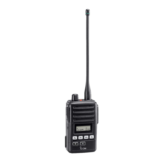
- Page 1 INSTRUCTION MANUAL VHF TRANSCEIVER iF50V UHF TRANSCEIVER iF60V This device complies with Part 15 of the FCC Rules. Operation is subject to the condition that this device does not cause harmful interference.
- Page 2 This radio has been tested and complies with the FCC RF exposure lim- RF exposure compliance requirements to be exceeded. The radio is its for “Occupational Use Only”. In addition, your Icom radio complies with transmitting when the “TX indicator” lights red. You can cause the the following Standards and Guidelines with regard to RF energy and radio to transmit by pressing the “PTT”...
-
Page 3: Important
Changes or modifications to this device, not expressly approved by Icom, Icom Inc. and the logo are registered trademarks of Icom Incorpo- Icom Inc., could void your authority to operate this transceiver under rated (Japan) in the United States, the United Kingdom, Germany, France, Spain, FCC regulations. -
Page 4: Table Of Contents
ACCESSORIES I Supplied accessories TABLE OF CONTENTS SAFETY TRAINING INFORMATION …………………………………………… i Antenna Battery pack Jack cover Key sticker* IMPORTANT ……………………………………………………………………… iii EXPLICIT DEFINITIONS ………………………………………………………… iii OPERATING NOTES …………………………………………………………… iii PRECAUTIONS ………………………………………………………………… iv TABLE OF CONTENTS ………………………………………………………… v 1 ACCESSORIES ……………………………………………………………… 1–3 ‘... - Page 5 ACCESSORIES ACCESSORIES I Accessory attachments ï Jack cover Attach the jack cover when the optional equipment is not used. D Flexible antenna To attach the jack cover: To detach the jack cover: q Insert the jack cover into the e Unscrew the screw using a Connect the supplied flexible antenna [SP MIC] jack.
-
Page 6: Panel Description
PANEL DESCRIPTION PANEL DESCRIPTION I Front, top and side panels r EXTERNAL SPEAKER-MICROPHONE JACK [SP MIC] Connects the optional speaker-microphone, etc. [SP MIC] jack cover NOTE: KEEP the [SP MIC] jack cover attached to the transceiver when the optional Speaker equipment is not used. - Page 7 PANEL DESCRIPTION PANEL DESCRIPTION I Function display i BATTERY INDICATOR Appears or blinks when the battery power decreases to a speci- fied level. o ALPHANUMERIC DISPLAY Displays an operating channel number, channel names, Set mode contents, DTMF code, etc. BIIS operation only q RECORD INDICATOR MDC operation only ➥...
-
Page 8: Programmable Function Keys
] and [ ] programmable function keys. after a specified time period has passed when scan is cancelled Consult your Icom dealer or system operator for details concerning except for this key. your transceivers programming. ➥ Push and hold this key for 1 sec. to indicate the scan group, then If the programmable function names are bracketed in the following select the desired group using [CH Up]/[CH Down]. - Page 9 PANEL DESCRIPTION PANEL DESCRIPTION MONITOR KEY TALK AROUND KEY ➥ Mute and release the CTCSS (DTCS) or 2-tone squelch mute. Push to turn the talk around function ON and OFF. • The talk around function equalizes the transmit frequency to the re- Open any squelch/deactivate any mute while pushing and hold- ceive frequency for transceiver-to-transceiver communication.
- Page 10 PANEL DESCRIPTION PANEL DESCRIPTION EMERGENCY KEYS COMPANDER KEY Push and hold to transmit the emergency call. Push to turn the compander function ON and OFF. • The emergency call is transmitted with beep emission and no display The compander function reduces noise components from the trans- changes.
-
Page 11: Basic Operation
BASIC OPERATION BASIC OPERATION I Turning power ON I Call procedure q Rotate [VOL] to turn power ON. When your system employs tone signalling (excluding CTCSS and • When the opening vibration function is turned ON, the transceiver DTCS), the call procedure may be necessary prior to voice trans- vibrates for 2 sec. -
Page 12: Receiving And Transmitting
BASIC OPERATION BASIC OPERATION I Receiving and transmitting D Receiving note NOTE: Transmitting without an antenna may damage the trans- ceiver. See p. 2 for antenna attachment. • Vibration function (Depends on the version) When the matched RX code signal is received, the transceiver may Receiving: vibrate for a specified time period depends on the pre-setting. - Page 13 BASIC OPERATION BASIC OPERATION D TX code channel selection D TX code number edit (PMR operation only) If the transceiver has [TX Code CH Select] assigned to it, the indi- If the transceiver has [TX Code CH Select] or [TX Code Enter] as- cation can be toggled between the operating channel number (or signed to it, TX code contents can be edited within the allowable digits.
-
Page 14: User Set Mode
BASIC OPERATION BASIC OPERATION I Emergency transmission D DTMF transmission If the transceiver has [DTMF Autodial] assigned to it, the automatic When [Emergency] is pushed, an emergency signal is automatically DTMF transmission function is available. Up to 8 DTMF channels are available. -
Page 15: Recording Function
BASIC OPERATION BASIC OPERATION I Recording function (Depends on the version) r Push [Playback/Rec] again to stop recording. The transceiver has a recording function that records the TX/RX • “ ” stops blinking. voice messages. When the specified ID is received, the automatic •... -
Page 16: Battery Charging
Icom radios or Icom charger. Only Icom battery packs are ness can result. Rinse your eyes with clean water, without rubbing tested and approved for use and charge with Icom radios or Icom them, and see a doctor immediately. - Page 17 CAUTION! DO NOT charge the battery outside of the specified the charger adapter. temperature range: 0˚C to +45˚C; +32˚F to +113˚F. Icom recom- mends charging the battery at +20˚C (+68˚F). The battery may heat Charge indica- tor lights green up or rupture if charged out of the specified temperature range.
- Page 18 BATTERY CHARGING BATTERY CHARGING D For your convenience ï AD-100 installation The AD-100 must be installed into the BC-119N CHARGER ADAPTER or BC-121N before battery charging. ➥ Connect the AD-100 and the BC-119N/BC- CHARGER ADAPTER 121N as below, then install the AD-100 into the holder space of the BC-119N or BC-121N with the supplied screws.
- Page 19 BATTERY CHARGING BATTERY CHARGING D Rapid charging with the BC-119N+AD-100 D Rapid charging with the BC-121N+AD-100 The optional BC-119N provides rapid charging of optional Li-Ion The optional BC-121N allows up to 6 battery packs to be charged battery packs. The following items are additionally required: simultaneously.
-
Page 20: Caution
BATTERY CASE BATTERY CASE I Optional battery case (BP-226) When using the optional battery case attached to the transceiver, Latch BP-226 Fig.1 install 5 × AA (LR6) size alkaline batteries as illustrated at right. The BP-226 employs waterproof construction, which correspond to IPX4 of the international standard IEC 60529 (2001). -
Page 21: Speaker-Microphone
SPEAKER-MICROPHONE SPEAKER-MICROPHONE I Optional HM-168 description I Attachment Attach the connector of the speaker-microphone into the [SP MIC] Alligator type clip jack on the transceiver and tighten the screw. To attach the speaker-mic. to your shirt or collar, etc. PTT switch Transmits while pushed Receives while released Microphone... -
Page 22: Swivel Beltclip
SWIVEL BELT CLIP SWIVEL BELT CLIP I MB-86 contents e Once the transceiver is locked in place, it will swivel 360 de- grees. Qty. q Belt clip ………………………………………………………………… 1 w Base clip ……………………………………………………………… 1 e Screws ………………………………………………………………… 2 I Attaching q Attach the stopper to the back of the transceiver. -
Page 23: Options
OPTIONS OPTIONS D D BATTERY PACK/CASE D D DC CABLES • BP-226 • CP-17L BATTERY CASE CIGARETTE LIGHTER CABLE Battery case for 5 × AA (LR6) alkaline cells. Allows charging of the battery pack through a 12 V cigarette lighter •... - Page 24 ï About VS-1SC VOX / PTT CASE VOX gain and delay adjustment The VS-1SC is a VOX/PTT unit for Icom handheld transceivers, qAttach the connector of the VS-1SC into the [SP/MIC] con- and allows you hands-free operation. nector on the transceiver and tighten the screw.
- Page 25 A-6604?-1EX Printed in Japan © 2007 Icom Inc. 1-1-32 Kamiminami, Hirano-ku, Osaka 547-0003, Japan Printed on recycled paper with soy ink.