Table of Contents
Advertisement
Quick Links
Installation, Operation, and Maintenance
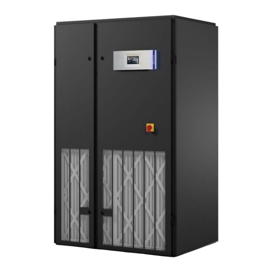
CyberOne EC CW
Perimeter Precision Air Conditioners
12-35 kW / 60 Hz
Only qualified personnel should install and service the equipment. The installation, starting up, and servicing of
heating, ventilating, and air-conditioning equipment can be hazardous and requires specific knowledge and training.
Improperly installed, adjusted or altered equipment by an unqualified person could result in death or serious injury.
When working on the equipment, observe all precautions in the literature and on the tags, stickers, and labels that are
attached to the equipment.
December 2020
SAFETY WARNING
AH-SVX010C-EN
Advertisement
Table of Contents

Related Manuals for Trane CyberOne EC CW


Summary of Contents for Trane CyberOne EC CW
- Page 1 Installation, Operation, and Maintenance CyberOne EC CW Perimeter Precision Air Conditioners 12-35 kW / 60 Hz SAFETY WARNING Only qualified personnel should install and service the equipment. The installation, starting up, and servicing of heating, ventilating, and air-conditioning equipment can be hazardous and requires specific knowledge and training.
- Page 2 PRIOR to Practices servicing the unit. NEVER PERFORM ANY SWITCHING, DISCONNECTING, OR VOLTAGE Trane® believes that responsible refrigerant practices are TESTING WITHOUT PROPER ELECTRICAL PPE AND important to the environment, our customers, and the air conditioning industry. All technicians who handle ARC FLASH CLOTHING.
- Page 3 Copyright This document and the information in it are the property of Trane®, and may not be used or reproduced in whole or in part without written permission. Trane® reserves the right to revise this publication at any time, and to make changes to its content without obligation to notify any person of such revision or change.
-
Page 4: Table Of Contents
....15 CyberOne EC CW Floor Mounted Systems Main Power ......15 Controls . -
Page 5: Model Number Description
Model Number Description CyberOne EC CW Floor Mounted Systems Digit 1, 2, 3, 4, 5 — System About Digits TR-COS = CyberOne Model numbers are comprised of Digit 6, 7, 8 — Capacity MBH digits. Each digit, or set of digits, defines the product model. -
Page 6: Introduction
Trane® to insure continuous operation. Using substitute parts or bypassing electrical or The CyberOne EC CW is housed in a steel frame type refrigeration components in order to continue operation is cabinet and is rated for indoor use. The exterior of the not recommended and will void the warranty. - Page 7 Introduction Figure 2. Typical CW internal layout- downflow configuration SMOKE DETECTOR T/H SENSOR (OPTIONAL) FILTER STEAM FIRESTAT DISTRIBUTOR (OPTIONAL) ELECTRIC BOX AIR PROVING CHILLED WATER DISCONNECT SWITCHES COIL SWITCH (NOTE 1) HOT WATER REHEAT COIL HUMIDIFIER DRAIN PAN HUMIDIFIER CONTROL BOARD ENCLOSURE CONDENSATE PUMP...
-
Page 8: Circuit Breakers/Motor Start Protectors
Circuit Breakers/Motor Start Protectors in the supply air stream after the cooling coils to reheat CyberOne EC CW systems incorporate state of the art supply air, as may be required to offset the sensible component protection with the use of motor start cooling of the system during the dehumidification cycle, protectors and circuit breakers located in the electric box. -
Page 9: Firestat
Introduction Smoke Detector Optionally mounted in the return air stream, a photo- electric smoke detector is used to sense the presence of smoke and signal the controller when a smoke alarm condition exists. The controller responds by shutting down the system. Firestat Optionally mounted in the return air stream, a fire detector senses high return air temperature and signals the... -
Page 10: Installation
Trane® ships all equipment FOB. Should any damage be present, notify Trane® Product CyberOne EC CW systems are designed to be kept in a Support prior to attempting any repairs. Refer to “Product vertical position. The unit is shipped on a skid to facilitate Support,”... -
Page 11: Conditioned Space
14). Pilot holes for piping and wiring are located on the Important: Ensure that the mounting surface is capable CyberOne EC CW unit based on the configuration. On an of supporting the equipment. Before upflow configuration, the pilot holes are located in the top mounting the unit, refer to the weight table of the cabinet. -
Page 12: Upflow Configuration Air Patterns
Installation Upflow Configuration Air Patterns There are two basic return air patterns: top free return and top ducted return (refer to the figure above). In a configured unit, the conditioned supply air has two If ductwork is to be installed, always consult the local and methods of discharge: Ducted or through a 1-, 2- or 3-way state codes to determine ducting requirements. -
Page 13: Optional Equipment (Field Installed)
As an Installed) option, a 75 foot or 150 foot long cable may be provided by Trane®. Follow the steps below to mount the sensor. Note: Do not mount any optional equipment on the unit Figure 8. -
Page 14: Plenum Box Assembly
To install a plenum box, first apply a strip beneath the unit. Trane® provides two types of water of sealing foam around the top flange of the A/C unit or, detectors, installed as follows: run a bead of silicone sealant. -
Page 15: Humidifier
MUST be within ±10% of the voltage specified on the system nameplate. The CyberOne EC CW uses three phase power in a range of voltages. The operating voltage, frequency and phase provided to the unit must match the specifications on the unit nameplate (refer to Figure 12, p. -
Page 16: Controls
Three-Phase Wiring Connections CyberOne EC CW units are designed to have the L1, L2 and Sales Order Number: L3 supply wires connected to corresponding L1, L2 and L3 Model Number: TR- line terminals on the non-fused service switch. -
Page 17: Ec Fan
Refer to the operator’s manual provided under separate cover for the system controller. It is recommended that Trane® Product Support be contacted before making adjustments to the controller. AH-SVX010C-EN... -
Page 18: Startup And Commissioning
1. Replace all equipment removed prior to performing disconnect switch to the Off position. the start-up checks. 2. Apply power to the CyberOne EC CW system at the main power disconnect switch. 3. Ensure that all blowers and fans are rotating correctly and freely without any unusual noise. -
Page 19: Maintenance
Humidifier Systematic, periodic general maintenance of the CyberOne EC CW unit is required for optimal system The steam cylinder has a limited lifetime and must be performance. General maintenance should include, but replaced periodically. Because water conditions and... - Page 20 Maintenance prevent injury. Keep hands, clothing and tools clear of the electrical terminals and rotating components. Ensure that the footing is stable at all times. Table 1. Troubleshooting SYMPTOM PROBABLE CAUSE RECOMMENDATION Temperature set point too high/low. Adjust to correct temperature setting. Chilled Water Valve Fails to Open No control power to the chilled water valve.
-
Page 21: Field Service
Maintenance Table 1. Troubleshooting (continued) SYMPTOM PROBABLE CAUSE RECOMMENDATION Water supply has been turned off or not Connect and/or turn on water supply. connected. Humidifier switch is in “Off” position. Turn switch to “Auto/On” position. Electrical connections are loose. Tighten electrical connections. Humidifier circuit breaker tripped. -
Page 22: Air Filter Replacement
Maintenance Air Filter Replacement To change the air filters, open the front doors of the cabinet. The air filters are accessed from inside the cabinet (except for upflow units with rear return). For upflow units, the filters are located behind the air intake grilles. For downflow units, the filters are located at the top where the label “FILTER ACCESS”... -
Page 23: Product Support
Product Support Obtaining Warranty Parts Product Support provides aftermarket technical and field support, warranty authorization and part sales to contractors and end users. Factory authorized services are A support technician will provide troubleshooting available by request and include: assistance over the telephone. •... - Page 24 For more information, please visit trane.com or tranetechnologies.com. Trane has a policy of continuous product and product data improvement and reserves the right to change design and specifications without notice. We are committed to using environmentally conscious print practices.