Advertisement
Quick Links
INSTRUCTION
MANUAL
12 24 50 115 240
6
440
+
_
6706
12 24 50 115 240
6
440
+
_
6708
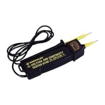
VOLTAGE
AND CONTINUITY
TESTERS
12-600V AC/DC (6706)
6-440V AC/DC (6708)
Read and understand this material
before operating or servicing this
equipment. Failure to understand
how to safely operate this tool could
result in an accident causing serious
injury or death.
999 9602.2
IM 1062 REV 4 8/97
© 1997 Greenlee Textron
A person who has not read
and does not understand all
operating instructions is not
qualified to operate this tool.
Failure to read and
understand safety
instructions may result
in injury or death.
Electric shock hazard:
Contact with live circuits
could result in severe injury
or death.
• Do not use the tester if it is wet
or damaged. Electric shock may result.
• Do not attempt to measure more
than 600 VDC/VAC with the 6706.
Do not attempt to measure more than
440 VDC/VAC with the 6708. Electric
shock may result.
• Disconnect the test leads before
removing the back of the case to
replace the battery. Opening the case
while the meter is connected to a circuit
can result in electric shock.
• Do not perform any service or mainte-
nance other than as described in the
manual. Unauthorized repairs will void
the warranty and may damage the
meter.
• Replace weak or discharged batteries
as soon as either of these conditions is
detected.
• Do use or store the meter in hot (more
than 135 F or 57 C) or humid (more
than 80% relative humidity) conditions.
Damage to the meter may result.
Failure to observe these precautions
could result in injury and damage to the
instrument.
SAVE THESE
INSTRUCTIONS!
Additional copies of this manual are
available upon request at no charge.
Specifications
Voltage Range .... 12–600V AC/DC (6706
6–440V AC/DC (6708)
Continuity Range ............................. 0–800K
Operating Temperature ................ 14 –120 F
-10 –50 C
Battery ........................................ (2) 1.5V AA
Size ........................................... 8" x 2" x 1.5"
20 x 5 x 3.75 cm
Storage Temperature ................. 14 –130 F
(-10 –56 C)
Preparation
Before using the tester, check it against a
functioning circuit. If the tester fails to
perform as expected, refer to the following
list until the problem is solved:
1. The probe tips are corroded.
2. The battery is weak or discharged.
3. A test lead is damaged.
4. The tester is damaged and needs to be
repaired.
Operation
To Locate a Hot Conductor
(AC Circuits Only)
1. Touch the fixed probe of the tester to the
terminal or conductor.
Note: Do not allow the loose probe to
contact anything.
2. Read the meter and listen for tone. See
the Hot Conductor Locator Table to
determine whether the fixed probe is on
a hot, neutral, or ground conductor.
To Check for Continuity or To Measure
Voltage (AC or DC Circuits)
1. Touch one probe tip to either terminal
or conductor; touch the other probe tip
to the other terminal or conductor.
2. Read the meter and listen for tone.
See the Continuity Check and Voltage
Measurement Table to determine
whether the fixed probe is on a hot,
neutral, or ground conductor.
Location and
Identification of LEDs
Indicates
approximate voltage
120 208 277
48
480
Indicates polarity
12
600
Indicates contact
with approximately
+
V
AC
50 volts or more
DC CONTINUITY
–
Indicates continuity
Maintenance
General
• Keep tester clean and dry.
• Wipe clean with a damp cloth. Let dry
completely before using.
Battery Condition
• Battery level is low when continuity test
L.E.D. and indication tone begin to lose
strength.
To Replace Batteries
1. Remove battery cover by prying with a
small screwdriver.
2. Remove batteries from holder.
3. Insert new batteries according to polarity
indicators, replace holder and cover.
Lifetime Limited Warranty
Greenlee warrants to the original purchaser
of these goods for use that these products
will be free from defects in workmanship and
material for their useful life, excepting
normal wear and abuse. This warranty is
subject to the same terms and conditions
contained in Greenlee's standard one year
limited warranty.
For all Test Instrument repairs,
ship units Freight Prepaid to:
Greenlee Textron at
4411 Boeing Drive
Rockford, IL 61109-2932 USA.
Mark all packages:
Attention TEST INSTRUMENT REPAIR.
For items not covered under warranty (such
as dropped, abused, etc.), repair cost quote
available upon request.
Note: Prior to returning any test instrument,
please check replaceable batteries
or make sure the battery is at
full charge.
MANUAL DE
)
INSTRUCCIONES
12 24 50 115 240
6
440
+
_
6706
6708
PROBADORES DE
VOLTAJE Y
CONTINUIDAD
12-600V CA/CC (6706)
6-440V CA/CC (6708)
Lea y comprenda esta información
antes de operar y de dar servicio
a este equipo. Si no se comprende
la manera segura de operar esta
herramienta, se puede sufrir un
accidente que puede producir
lesiones graves o la muerte.
999 9602.2
IM 1062 REV 4 8/97
© 1997 Greenlee Textron
Una persona que no haya
leído o no comprenda todas
las instrucciones de operación
no está calificada para operar
esta herramienta.
Si no se leen ni comprenden
las instrucciones de
seguridad, se pueden
producir lesiones o la muerte.
Peligro de choque eléctrico:
El contacto con los circuitos
cargados puede producir
lesiones graves o la muerte.
• No use el probador si está mojado o
dañado. Se puede producir un choque
eléctrico.
• Utilice el probador 6706 para medir
solamente tensiones de 600 VCC/VCA
o el probador 6708 para medir
tensiones de 400 VCC/VCA o menores,
a fin de evitar un choque eléctrico.
• Desconecte los conductores de prueba
antes de retirar el panel posterior de la
caja para subsituir la batería. Si se abre
la caja cuando el medidor está
conectado a un circuito, se puede
producir un choque eléctrico.
• Solamente se permite la realización de
los procedimientos de servicio y
mantenimiento descritos en el manual.
Las reparaciones no autorizadas anulan
la garantía y pueden dañar el medidor.
• Substituya inmediatamente las baterías
que están débiles o descargadas.
• No use ni almacene el medidor cuando
existan condiciones de alta temperatura
(más de 57 C o 135 F) o de humedad
(más de 80% de humedad relativa).
Se puede dañar el medidor.
Si no se observan estas precauciones, se
pueden producir lesiones y el instrumento
se puede dañar.
¡
GUARDE ESTAS
INSTRUCCIONES!
Se pueden obtener copias adicionales
de este manual gratis.
Especificaciones
Gama de voltaje . 12–600V CA/CC (6706
6–440V CA/CC (6708)
Gama de continuidad ..................... 0-800K
Temperatura de operación ........... -10 –50 C
Batería ........................................ (2) 1,5V AA
Tamaño ..................................... 8" x 2" x 1,5"
Temperatura de almacenamiento ... -10 –56 C
Preparación
Antes de usar el probador, revíselo usando
un circuito en funcionamiento. Si el probador
no funciona como se espera, refiérase a la
lista a continuación antes de proseguir:
1. Las puntas de la sonda están corroídas.
2. La batería está débil o descargada.
12 24 50 115 240
6
440
+
_
3. Un conductor de prueba está dañado.
4. El probador está dañado y necesita
reparaciones.
Operación
Cómo Detectar un Conductor Cargado
(Para los circuitos de CA solamente)
1. Establezca un contacto entre la sonda fija
del probador y el terminal o conductor.
Aviso: No permita que la sonda móvil
entre en contacto con objeto
alguno.
2. Lea el medidor y esté atento al tono.
Vea la «Tabla de Detección de
Conductores Cargados» para determinar
si la sonda fija está en un conductor
cargado, neutro o de conexión a tierra.
Cómo Revisar la Continuidad
o Medir el Voltaje (Circuitos de CA o CC)
1. Establezca un contacto entre la punta de
una sonda y el terminal o el conductor;
establezca un contacto entre la otra
punta de la sonda y el otro terminal o
conductor.
2. Lea el medidor y esté atento al tono.
Vea la «Tabla de Revisión de
Continuidad y Medición de Voltaje» para
determinar si la sonda fija está en un
conductor cargado, neutro o de conexión
a tierra.
Ubicación e Identificación de los
LEDs (diodos emisores de luz)
120 208 277
48
480
12
600
+
V
AC
DC CONTINUITY
–
Mantenimiento
Generalidades
• Mantenga el probador limpio y seco.
• Límpielo con un paño húmedo. Permita que
se seque completamente antes de usarlo.
Condición de la Batería
• El nivel de la batería está bajo cuando el
LED de la prueba de continuidad y el tono
de indicación comienzan a perder
intensidad.
Cómo Substituir las Baterías
1. Remueva la cubierta de la batería
palanqueándola con un destornillador
pequeño.
2. Remueva las baterías del soporte.
3. Inserte las baterías nuevas según los
indicadores de polaridad, vuelva a
colocar el soporte y la cubierta.
Garantía Limitada de por Vida
Greenlee le garantiza al comprador original
que estos productos estarán libres de
defectos en la mano de obra y en los
materiales durante toda su vida útil, excepto
por el desgaste normal y el abuso. Esta
garantía está sujeta a los mismos términos y
condiciones que se encuentran en la garantía
limitada estándar por un año de Greenlee.
De ser necesario llevar a cabo reparaciones,
envíe las unidades a porte pagado a:
Greenlee Textron
4411 Boeing Drive
Rockford, IL 61109-2932 EE.UU.
Escriba en todos los empaques:
Atención: TEST INSTRUMENT REPAIR
(Reparaciones de los instrumentos de prueba)
En el caso de aquellos artículos que no están
cubiertos por la garantía (por ejemplo, que
hayan sufrido caídas, abusos, etc.) podemos
cotizarle el costo de la reparación, a solicitud.
Aviso: Antes de devolver cualquier
instrumento de prueba, haga el favor
de revisar las baterías reemplazables
o asegurarse que la batería esté
completamente cargada.
)
(14 –120 F)
20 x 5 x 3,75 cm
(14 –130 F)
Indica el voltaje
aproximado
Indica la polaridad
Indica todo contacto
igual o superior
a 50 voltios
Indica la continuidad
Advertisement

Related Manuals for Greenlee 6706


Summary of Contents for Greenlee 6706
- Page 1 • No use el probador si está mojado o dañado. Se puede producir un choque eléctrico. • Utilice el probador 6706 para medir solamente tensiones de 600 VCC/VCA o el probador 6708 para medir tensiones de 400 VCC/VCA o menores, a fin de evitar un choque eléctrico.
- Page 2 1. Retirez le couvercle du compartiment décharges électriques. • Utiliser uniquement le testeur 6706 pour mesurer des tensions de 600 V (ca/cc) maximum et le testeur 6708 pour les 2. Retirez les piles de leur support.