Table of Contents
Advertisement
Available languages
Available languages
MANUAL DE INSTRUCCIONES
5702
PHASE SEQUENCE
INDICATOR
INDICADOR DE
SECUENCIA DE FASE
INDICATEUR DE
SEQUENCE DE
PHASE
999 3286.5
INSTRUCTION MANUAL
MANUEL D'INSTRUCTIONS
Read and understand all of the instructions and safety
information in this manual before operating or servicing
this tool.
Lea y entienda todas las instrucciones y la información
sobre seguridad que aparecen en este manual, antes de
manejar estas herramientas o darles mantenimiento.
Lire attentivement et bien comprendre toutes les
instructions et les informations sur la sécurité de ce manuel
avant d'utiliser ou de procéder à l'entretien de cet outil.
© 2001 Greenlee Textron
5123
MOTOR ROTATION
INDICATOR
INDICADOR DE
ROTACIÓN DEL MOTOR
INDICATEUR DE
ROTATION DU MOTEUR
IM 1424 REV 1 10/01
Advertisement
Table of Contents

Related Manuals for Greenlee 5123


Summary of Contents for Greenlee 5123
- Page 1 à l’entretien de cet outil. 999 3286.5 MOTOR ROTATION INDICADOR DE ROTACIÓN DEL MOTOR INDICATEUR DE ROTATION DU MOTEUR © 2001 Greenlee Textron 5123 INDICATOR IM 1424 REV 1 10/01...
- Page 2 This ensures that the motor will rotate in the proper direction when power is applied to the circuit. Use the 5123 Motor Rotation Indicator to identify the legs of the motor; use the 5702 Phase Sequence Indicator to identify the phases of the circuit.
-
Page 3: Important Safety Information
Immediate hazards which, if not avoided, WILL result in severe injury or death. Hazards which, if not avoided, COULD result in severe injury or death. Hazards or unsafe practices which, if not avoided, MAY result in injury or property damage. SAFETY ALERT SYMBOL 5702 • 5123... - Page 4 Important Safety Information Electric shock hazard: • Do not use the unit if it is wet or damaged. • Use test leads or accessories that are appropriate for the application. See the category and voltage rating of the test lead or accessory.
- Page 5 • Do not operate with the case open. • Before opening the case, remove the test leads from the circuit and shut off the unit. Failure to observe these warnings can result in severe injury or death. 5702 • 5123...
- Page 6 Important Safety Information Do not connect the 5123 unit to live voltage. Failure to observe this precaution can result in injury and can damage the unit. • Do not attempt to repair this unit. It contains no user-serviceable parts. • Do not expose the unit to extremes in temperature or high humidity.
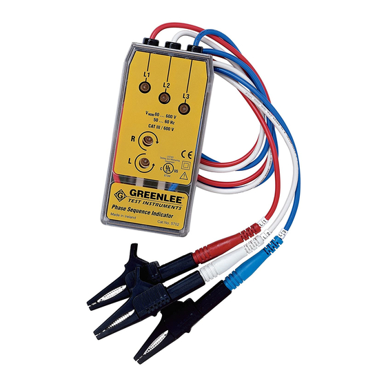
- Page 7 Identification 5702 Phase Sequence Indicator Leads (red, white and blue) Phase Indicators Clockwise Indicator Counterclockwise Indicator 5123 Motor Rotation Indicator Leads (red, white and blue) Clockwise Indicator Counterclockwise Indicator 5702 • 5123...
- Page 8 Operation—5702 Phase Sequence Indicator Identifying the Phase Sequence of the Circuit Shut off and lock out power. Attach the red, white and blue leads of the 5702 to the three phases of the circuit. Energize the circuit. Read the tester: •...
- Page 9 • Clockwise is the reference direction — regardless of the required direction of motor rotation, the user must spin the motor shaft clockwise to correctly identify the motor wires. Attach the red, white and blue leads of the 5123 to the three motor wires. 5702 • 5123...
- Page 10 Operation—5123 Motor Rotation Indicator (cont’d) Press the test button while rotating the shaft clockwise. • If clockwise rotation is required and the clockwise indicator is illuminated, tag the motor wires to correspond with the Motor Rotation Indicator leads. • If clockwise rotation is required and the counterclockwise indicator is illuminated, switch the red and white leads and re-test.
-
Page 11: Battery Replacement
Battery Replacement (5123) Before opening the case, remove the test leads from the circuit and shut off the unit. Failure to observe these warnings can result in severe injury or death. Disconnect the unit from the circuit. Turn the unit OFF. -
Page 12: Specifications
Operating/Storage Temperature Range: 0 C to 40 C (32 F to 104 F) Remove battery. Battery: 9-Volt (NEDA 1604, JIS 006P or IEC 6F22) Do not connect the 5123 unit to live voltage. Failure to observe this precaution can result in injury and can damage the unit. -
Page 13: Acerca De La Seguridad
Esto garantizará que el motor rote en la dirección correcta una vez que se aplique energía al circuito. Utilice el Indicador de rotación del motor modelo 5123 para identificar las patas del motor; utilice el Indicador de secuencia de fase modelo 5702 para identificar las fases del circuito. -
Page 14: Importante Información Sobre Seguridad
Importante Información sobre Seguridad Este símbolo se utiliza para indicar un riesgo o práctica poco segura que podría ocasionar lesiones o daños materiales. Cada uno de los siguientes términos denota la gravedad del riesgo. El mensaje que sigue a dichos términos le indica cómo puede evitar o prevenir ese riesgo. - Page 15 Utilizarla sin comprender cómo manejarla de manera segura podría ocasionar un accidente y, como resultado de éste, graves lesiones o incluso la muerte. Peligro de electrocución: El contacto con circuitos activados puede ocasionar graves lesiones o incluso la muerte. 5702 • 5123...
- Page 16 Importante Información sobre Seguridad Peligro de electrocución: • No aplique más del voltaje nominal entre dos terminales de entrada cualesquiera, o entre una terminal de entrada cualquiera y una conexión a tierra. • No toque las puntas de los cables de prueba ni ninguna parte del accesorio que carezca de forro aislante.
- Page 17 Importante Información sobre Seguridad No conecte la unidad modelo 5123 a líneas de tensión activadas. De no observarse esta advertencia podrían sufrirse lesiones o daños a la unidad. • No intente reparar esta unidad, ya que contiene piezas que deben recibir mantenimiento por parte de un profesional.
- Page 18 Indicadors de fase Indicador de rotación en sentido horario Indicador de rotación en sentido antihorario Indicador de rotación del motor modelo 5123 Cables de prueba (rojo, blanco y azul) Indicador de rotación en sentido horario Indicador de rotación en sentido antihorario...
- Page 19 Energice el circuito. Ahora el medidor deberá indicar rotación en sentido horario. Peligro de electrocución: El contacto con circuitos activados puede ocasionar graves lesiones o incluso la muerte. 5702 • 5123...
- Page 20 Sujete los cables de prueba rojo, blanco y azul de la unidad 5123 a cada uno de los tres alambres del motor.
- Page 21 Operación—5123 Indicador de Rotación del Motor (continuación) Oprima el botón de prueba al tiempo que hace rotar el eje del motor en el sentido horario. • Si se requiere que el motor gire en sentido horario, y el indicador de sentido horario se enciende, marque los cables del motor de modo que correspondan con los cables de prueba del Indicador de rotación del motor.
- Page 22 Cómo reemplazar la pila (5123) Antes de abrir la caja, retire del circuito los cables de prueba y apague la unidad. De no observarse estas advertencias pueden sufrirse graves lesiones o incluso la muerte. Desconecte la unidad del circuito. Apague la unidad.
-
Page 23: Especificaciones
0 C a 40 C (32 F a 104 F) Retire la pila. Pila: 9 voltios (NEDA 1604, JIS 006P o IEC 6F22) No conecte la unidad modelo 5123 a líneas de tensión activadas. De no observarse esta advertencia podrían sufrirse lesiones o daños a la unidad. - Page 24 Greenlee Textron / Subsidiary of Textron Inc. 4455 Boeing Dr., Rockford, IL 61109-2988 815/397-7070...
- Page 25 Utiliser l’indicateur de rotation du moteur 5123 pour identifier l’enroule- ment du moteur et l’indicateur de séquence de phase 5702 pour identifier les phases du circuit.
-
Page 26: Consignes De Sécurité Importantes
Consignes de sécurité importantes Ce symbole met en garde contre les risques et les manipulations dangereuses pouvant entraîner des blessures ou l’endommage- ment du matériel. Le mot indicateur, défini ci-dessous, indique la gravité du danger. Le message qui suit le mot indicateur indique comment empêcher le danger. - Page 27 Risques de décharge électrique : Un contact avec des circuits sous tension peut entraîner des blessures graves, voire mortelles. 5702 • 5123...
- Page 28 Consignes de sécurité importantes Risques de décharge électrique : • Ne pas appliquer plus que la tension nominale entre deux bornes d’entrée, ou entre une borne d’entrée et une prise de terre. • Ne pas entrer en contact avec les extrémités du fil d’essai ou avec toute autre partie non isolée de l’accessoire.
- Page 29 Consignes de sécurité importantes Ne pas brancher l’appareil 5123 à de la tension. L’inobservation de cette consigne peut endommager l’appareil et entraîner des blessures. • Ne pas tenter de réparer cet appareil. Il ne comporte aucune pièce pouvant être réparée.
- Page 30 Identification Indicateur de séquence de phase 5702 Fils (rouge, blanc et bleu) Indicateurs de phase Indicateur, sens horaire Indicateur, sens antihoraire Indicateur de rotation du moteur 5123 Fils (rouge, blanc et bleu) Indicateur, sens horaire Indicateur, sens antihoraire...
- Page 31 électrique et échanger les fils rouge et blanc. Mettre le circuit sous tension Le compteur doit maintenant indiquer le sens horaire. Risques de décharge électrique : Un contact avec des circuits sous tension peut entraîner des blessures graves, voire mortelles. 5702 • 5123...
- Page 32 • Le sens horaire correspond à la direction de référence — quelle que soit la direction du moteur, l’utilisateur doit faire tourner l’arbre du moteur dans le sens horaire pour identifier correctement les fils du moteur. Attacher les fils rouge, blanc et bleu du modèle 5123 aux trois fils du moteur.
- Page 33 Utilisation—5123 Indicateur de Rotation du Moteur (suite) Appuyer sur le bouton de vérification tout en faisant tourner l’arbre dans le sens horaire. • Si une rotation dans le sens horaire est nécessaire et que l’indicateur du sens horaire est allumée, identifier les fils du moteur pour qu’ils correspondent à...
-
Page 34: Remplacement De La Pile
Remplacement de la pile (5123) Avant d’ouvrir le boîtier, retirer les fils d’essai du circuit et mettre l’appareil hors tension. L’inobservation de ces consignes peut entraîner des blessures graves, voire mortelles. Débrancher l’appareil du circuit. Mettre l’appareil hors tension (OFF). -
Page 35: Spécifications
0 à 40 C (32 à 104 F). Enlever la pile. Pile : 9 volts (NEDA 1604, JIS 006P ou IEC 6F22) Ne pas brancher l’appareil 5123 à de la tension. L’inobservation de cette consigne peut endommager l’appareil et entraîner des blessures. - Page 36 Lifetime Limited Warranty Greenlee warrants to the original purchaser of these goods for use that these products will be free from defects in workmanship and material for their useful life, excepting normal wear and abuse. This warranty is subject to the same terms and conditions contained in Greenlee’s standard one-year limited warranty.