Greenlee 6706, 6708 - Voltage And Continuity Testers Manual
- Instruction manual (2 pages)
Advertisement
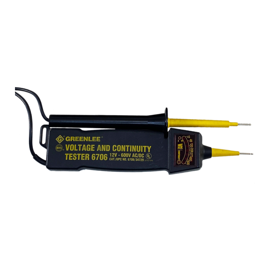
VOLTAGE AND CONTINUITY TESTERS
12-600V AC/DC (6706)
6-440V AC/DC (6708)
Specifications
Voltage Range: 12–600V AC/DC (6706  )
)
6–440V AC/DC (6708)
Continuity Range: 0–800KΩ
Operating Temperature: 14º–120º F
-10º–50º C
Battery: (2) 1.5V AA
Size: 8" x 2" x 1.5"
20 x 5 x 3.75 cm
Storage Temperature: 14º –130º F
(-10º–56º C)
Preparation
Before using the tester, check it against a functioning circuit. If the tester fails to perform as expected, refer to the following list until the problem is solved:
- The probe tips are corroded.
- The battery is weak or discharged.
- A test lead is damaged.
- The tester is damaged and needs to be repaired.
Operation
To Locate a Hot Conductor (AC Circuits Only)
- Touch the fixed probe of the tester to the terminal or conductor.
Note: Do not allow the loose probe to contact anything. - Read the meter and listen for tone. See the Hot Conductor Locator Table to determine whether the fixed probe is on a hot, neutral, or ground conductor.
To Check for Continuity or To Measure Voltage (AC or DC Circuits)
- Touch one probe tip to either terminal or conductor; touch the other probe tip to the other terminal or conductor.
- Read the meter and listen for tone. See the Continuity Check and Voltage Measurement Table to determine whether the fixed probe is on a hot, neutral, or ground conductor.
Location and Identification of LEDs

Maintenance
General
- Keep tester clean and dry.
- Wipe clean with a damp cloth. Let dry completely before using.
Battery Condition
- Battery level is low when continuity test L.E.D. and indication tone begin to lose strength.
To Replace Batteries
- Remove battery cover by prying with a small screwdriver.
- Remove batteries from holder.
- Insert new batteries according to polarity indicators, replace holder and cover.
Hot Conductor Locator Table
| Type of Circuit | Connection | Indications |
| AC circuit | fixed probe: hot loose probe: no contact | voltage: no indication polarity: no indication continuity: illuminated audible: tone |
| AC circuit | fixed probe: neutral or ground loose probe: no contact | voltage: no indication polarity: no indication continuity: no indication audible: no indication |
Continuity Check and Voltage Measurement Table
| Type of Circuit | Connection | Indications |
| Energized AC circuit | either probe: hot either probe: neutral or ground | voltage: illuminated polarity: illuminated continuity: illuminated audible: tone |
| Energized DC circuit | fixed probe: + loose probe: – | voltage: illuminated polarity: no indication continuity: no indication audible: no tone |
| Energized DC circuit | fixed probe: – loose probe: + | voltage: lowest value not illuminated polarity: illuminated continuity: illuminated audible: tone |
| Unenergized AC or DC circuit | either probe: any conductor either probe: any conductor | voltage: no indication polarity: no indication continuity: illuminated* audible: tone* |
* if circuit resistance is less than approximately 800Ω

Documents / ResourcesDownload manual
Here you can download full pdf version of manual, it may contain additional safety instructions, warranty information, FCC rules, etc.
Download Greenlee 6706, 6708 - Voltage And Continuity Testers Manual
Advertisement
Thank you! Your question has been received!


Need Assistance?
Do you have a question about the 6706 that isn't answered in the manual? Leave your question here.