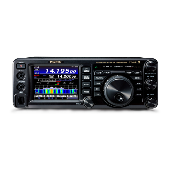
Yaesu FT-991A Operating Manual
Hf/vhf/uhf all mode
Hide thumbs
Also See for FT-991A:
- Technical supplement (132 pages) ,
- Reference manual (21 pages) ,
- Instruction manual (15 pages)
Table of Contents
Advertisement
Quick Links
Advertisement
Table of Contents

Related Manuals for Yaesu FT-991A


Summary of Contents for Yaesu FT-991A
- Page 1 HF/VHF/UHF All Mode Transceiver FT-991 Operating Manual...
- Page 2 Before using your FT-991A , be sure to read and follow the instructions in the “Before You Begin” section of this manu- About TFT Displays FT-991A utilizes a TFT liquid-crystal display.
-
Page 3: General Description
The distance and direction information The FT-991A is equipped with a 3.5 inch full-color TFT of the call sign members of the group may be shown on display. Functions, including the receiving band, the noise the TFT display. - Page 4 General Description DNR ( Digital Noise Reduction ) by DSP Real-Time Spectrum Scope and Multi-Color digital processing ( see page 56. ) Waterfall Display ( see page 42. ) The incorporated digital noise reduction circuit may be The spectrum scope function provides a visual display of set to the optimal working point by varying the 15 step the strength and distribution of signals across the band in parameters according to the noise type.
-
Page 5: Table Of Contents
Table of Contents WIDTH ( IF DSP Bandwidth ) Tuning General Description ..........1 ( SSB/CW/RTTY/DATA Modes ) ...52 Table of Contents ..........3 NARROW ( NAR ) One-Touch IF Filter Selection ...54 Safety Precautions ..........5 IF NOTCH Filter Operation Accessories &... - Page 6 Table of Contents Operation on Alaska Emergency Frequency: 5167.5 khz (U.S. Version Only) ... 112 VFO and Memory Scanning ......113 VFO Scanning ..........113 Memory Scan ............ 114 PMS (Programmable Memory Scanning) ..115 Using the GPS Function ........116 What is GPS? ............
-
Page 7: Safety Precautions
Safety Precautions Safety Precautions Note beforehand that the company shall not be liable for any damages suffered by the customer or third parties in using this product, or for any failures and faults that occur during the use or misuse of this product, unless otherwise provided for under the law. - Page 8 Safety Precautions Do not allow metallic objects such as wires Refrain from using headphones and ear- and water to get inside the product. phones at a loud volume. This may result in fire, electric shock and equip- Continuous exposure to loud volumes may result ment failure.
-
Page 9: Accessories & Options
Accessories & Options Supplied Accessories Hand Microphone ( MH-31 Spare Fuse ( 25A ) DC Power Cord Operating Manual Warranty Card World Map Sticker The illustrations above may vary slightly from the actual accessories. F T-991 Operating Manual Page 7... -
Page 10: Available Options
Accessories & Options Available Options For details, see “Installation of Optional Accessories” on page 143 or the catalog. Lightweight Stereo Headphone Remote Control Keypad Reference Microphone YH-77STA FH-2 Linear Amplifier/AC Power Supply External Automatic Antenna Tuner FC-40 VL-1000/VP-1000 Others ( equivalent to the supplied microphone ) Hand Microphone MH-31... -
Page 11: Before You Begin
The heavy wire stand on the bottom of the transceiver allows the transceiver to be tilted upward for better viewing. Sim- ply fold the stand forward to raise the front of the transceiver, and fold it back against the bottom case to lower the front of the FT-991A. Adjusting the Main Tuning Dial Torque The torque ( drag ) of the Main Tuning Dial knob may be adjusted according to your preferences. -
Page 12: Adjusting The Clock
Before You Begin Adjusting the Clock Use the following procedure to adjust the clock shown at the top right of the LCD display. 1. Press and hold the MENU ( SETUP ) button. MENU ( SETUP ) button 2. Touch [ TIME/DATE ] on the LCD. 3. -
Page 13: Inputting The Call Sign
Before You Begin Inputting the Call Sign When turning on the power for the first time after purchase, or after resetting the transceiver, enter your own call sign. The call sign will be displayed on the start screen when turning on the power and will be used to identify the station when sending messages during digital communication. -
Page 14: Resetting The Microprocessor
Once the transceiver comes on, you may release the buttons. Note: The FT-991A cannot erase the memory channels “01” ( and “5-01” through “5-10”: U.S. version ) . Menu Resetting Use this procedure to restore the Menu settings to their... -
Page 15: Antenna Considerations
Before You Begin Antenna Considerations The FT-991A is designed for use with any antenna system providing a 50 Ohm resistive impedance at the desired op- erating frequency. While minor excursions from the 50-Ohm specification are of no consequence, if the Standing Wave Ratio ( SWR ) present at the Antenna jack is greater than 3:1, the transceiver’s Automatic Antenna Tuner may not be able... -
Page 16: Grounding
Before You Begin Grounding The FT-991A transceiver, like any other HF communications apparatus, requires an effective ground system for maxi- mum electrical safety and best communications effectiveness. A good ground system can contribute to station efficiency in a number of ways: ... -
Page 17: Connection Of Antenna And Power Cables
Ensure adequate ventilation around the FT-991A, to prevent heat build-up and possible reduction of performance due to high heat. Do not install the FT-991A on an unstable desk or table. Do not place it in a location where objects may fall onto it from above. -
Page 18: Installation And Interconnections
If the FH-2 plug is removed from the jack while the FT-991A is in operation, the FT- 991A may be switched to the transmit mode. Turn off the power of the FT-991A before connecting or disconnecting the FH-2. Page 16... -
Page 19: Key, Keyer, And Computer-Driven Keying
Key, Keyer, and Computer-Driven Keying Interconnections The FT-991A includes many features for the CW operator. These functions will be detailed in the “CW Mode Opera- tion” section later. This 3.5 mm, 3-contact jack accepts a CW key or keyer paddles (for the built-in electronic keyer), or the output from an external electronic keyer. -
Page 20: Vl-1000 Linear Amplifier Interconnections
Installation and Interconnections VL-1000 Linear Amplifier Interconnections Be sure that both the FT-991A and VL-1000 are turned off, and then follow the installation recommendations contained in the illustration. Note: Refer to the VL-1000 Operating Manual for details regarding amplifier operation. -
Page 21: Plug/Connector Pinout Diagrams
Installation and Interconnections Plug/Connector Pinout Diagrams GPS/CAT ① DCD ② SERIAL OUT/RXD DOWN ⑨ ⑧ ⑦ ⑥ (GPS DATA IN) ③ SERIAL IN ④ DTR MIC GND ⑤ GND ⑥ DSR ⑤... -
Page 22: Front Panel Controls & Switches
( grounded ) shaft switch for one second to turn the transceiver off. of the plug, resulting in a constant “key-down” Connect the FT-991A transceiver to a com- condition. mercially available DC power supply. Turn the Key-up voltage is +3.3 V, and key-down current... - Page 23 Front Panel Controls & Switches F ( M-LIST ) Button MODE Button Switch the radio modulation form ( operating mode ) . Press the button briefly to display the function menu screen where the operation settings for a variety of Press this button to display the radio modulation functions may be configured.
- Page 24 ( QMB ) one by one. lected Menu item as the short cut. TUNE Button TXW Button This is the on/off switch for the FT-991A Automatic During a split operation, press and hold the TWX Antenna Tuner. button to listen on the transmitter frequency while m Press the [ TUNE ] button briefly to display the holding the button.
- Page 25 Front Panel Controls & Switches Main Tuning Dial Knob V/M Button This large knob adjusts the operating frequency of This button toggles frequency control between VFO- VFO-A. A and the memory system. Rotate clockwise to increase the operating frequency Pressing this button alternately recalls the VFO and rotate counter-clockwise to decrease the operat- frequency data and the frequency data saved in a ing frequency.
-
Page 26: About The Display
About the Display TFT Liquid Crystal Display A variety of information such as VFO-A/VFO-B frequencies, mode, S-meter will appear on the LCD. Operating mode Operation frequency Clock Mode (radio modulation form) GPS signal capturing HI-SWR MULTI knob operation VFO-B data Icons Clarifier operation S-meter... - Page 27 About the Display TFT Liquid Crystal Display Clock The voice memory/contest memory keyer func- PLAY Indicates the current time. tions are in use. PLAY: Playing, REC: Recording When receiving a GPS signal, the time is set automati- cally. S-Meter Displays the reception signal strength. GPS Signal Capturing Indicator Appears when an external GPS device is connected to the GPS/CAT jack on the rear panel and GPS signals...
-
Page 28: Led Indicators
About the Display LED Indicators Displays the transmit/receive status of the transceiver, and the main dial “FAST” and “LOCK”. RX Indicator LOCK Indicators TX Indicator FAST Indicators Memory Mode Main Band Sub Band RX/TX RX/TX Indicators Indicators Indicator RX Indicator ( Green ) Sub Band TX Indicator Red ( Right ) : This indicator illuminates when the squelch opens. -
Page 29: Rear Panel
Rear Panel GPS/CAT Jack Use this terminal to connect the transceiver to a good This is the RS-232C jack for connecting a computer earth ground, for safety and optimum performance. or a commercially available external GPS device. Use a large diameter, short braided cable to make Connecting a computer to this jack, using a com- the ground connections. - Page 30 To control the transceiver remotely from the computer, a USB driver is required. For details on the USB driver, visit the Yaesu website. When using a USB cable connected to a com- puter, the transceiver may change to the transmit mode when the computer is started.
-
Page 31: Mh-31A8J Microphone Switches
MH-31A8J Microphone Switches PTT Switch TONE Switch Switches transmission/reception. Switches transmission sound quality. Press to transmit and release to receive. Slide to the “1” side to make the transmit audio flat. Slide to the “2” side to emphasize transmit audio. DWN Button Press the DWN ( Down ) button to scan the frequency downward. - Page 32 Optional FH-2 Remote Control Switches With the optional remote control keypad FH-2, you can record and transmit your voice ( Voice Memory ) and control the Contest Memory Keyer during CW operation. m On SSB/AM modes, five channels of storage and playback of voice memory ( 20 seconds each ) , using your own voice for recording ( see page 70 ) .
-
Page 33: Optional Mh-36E8J Microphone Switches
Optional MH-36E8J Microphone Switches The optional MH-36E8J is a handheld microphone equipped with the DTMF function that enables DTMF ( Dual Tone Multi Frequencies ) transmission. A lamp switch illuminates the DTMF keypad for easy viewing in the dark. DWN Button DTMF Keypad Press to tune down, hold to start scanning. -
Page 34: Basic Operation: Receiving On Amateur Bands
Basic Operation: Receiving on Amateur Bands Before turning on the main power, please verify the following items once more. Have you made all ground connections securely? See page 14 for details. Do you have your antenna ( s ) connected to the rear-panel Antenna jack ( s ) ? See page 15 for details. ... - Page 35 Touch and hold [14] on the screen displayed by pressing the BAND button to selection 5 MHz is provided. The FT-991A utilizes a triple band-stack VFO selection technique, which permits storing up to three favorite frequencies and modes onto each VFO band register.
- Page 36 Basic Operation: Receiving on Amateur Bands 7. Rotate the Main Tuning Dial knob to tune around the band, and begin normal operation. Advice: Clockwise rotation of the Main Tuning Dial knob increases the operating frequency, one “step” of the synthesizer at a time; similarly, counter- clockwise rotation of the Main Tuning Dial knob will decrease the frequency.
-
Page 37: Operation On 60-Meter ( 5 Mhz ) Band
( U.S. and U.K. version only ) The recently-released 60-meter band is covered, in the FT-991A, by fixed memory channels. These channels are set to USB or CW, and they appear between the “last” PMS channel ( “P9U” ) and the first “regular” memory channel ( Channel 1 ) : 1. -
Page 38: Clar ( Clarifier ) Operation
VFO-A frequency. Four small numbers on the TFT Display show the current Clarifier offset. The Clarifier controls on the FT-991A are designed to allow setting a preset offset ( up to ±9.99 kHz ) without actually retuning, and then to activate it via the Clarifier CLAR button. -
Page 39: Lock
Basic Operation: Receiving on Amateur Bands LOCK You may lock the setting of the Main Tuning Dial knob ( for VFO-A frequency tuning ) to prevent accidental frequency change. Main Tuning Dial Knob Lock To lock the Main Tuning Dial knob, press the LOCK LOCK Button button that is located to the right of the Main Tuning Dial knob. -
Page 40: Vfo Color
Basic Operation: Receiving on Amateur Bands VFO COLOR The background color of the VFO-A frequency in the TFT display may be selected via Menu item 006. 1. Press the MENU button to enter the Menu mode. Background color 2. Rotate the MULTI knob to select Menu item “006 DISPLAY COLOR”. -
Page 41: Convenience Features
Band Stack Operation The FT-991A utilizes a triple band-stack VFO selection technique that permits storing of up to three favorite frequen- cies and modes onto each band VFO register. For example, one frequency each on 14 MHz CW, RTTY, and USB may be stored and then recalled by successive, momentary touches of [ 14 ] on the screen displayed by the BAND button. -
Page 42: Ams ( Automatic Mode Select ) Operation
Convenience Features AMS ( Automatic Mode Select ) Operation The transceiver has the AMS ( Automatic Mode Select ) function which enables the transceiver to automatically select the most appropriate option out of the three communication modes according to the received signal while operating in C4FM mode. - Page 43 Convenience Features AMS ( Automatic Mode Select ) Operation Setting the Operation of the AMS Function Using the AMS function switches the communication mode to match the received signal but you can alternatively select and lock the transmission mode. 1. Press the MENU ( SETUP ) button to enter the MENU ( SETUP ) Button Menu mode.
-
Page 44: Scope
Convenience Features SCOPE The SCOPE function provides a real time spectrum display of the band conditions. Both strong and weak signals can be clearly displayed on the TFT screen. In the MANUAL mode, the scope frequency spectrum is scanned one time and displayed. - Page 45 Convenience Features SCOPE Sweep Mode Two sweep modes are available for the scope function as described below. MANUAL Mode Touch [ SWEEP ] on the LCD to sweep across the band one time, and display band conditions. Continuous Sweeping Mode Touch and hold [ SWEEP ] on the LCD to begin the continuous sweep operation.
-
Page 46: More Frequency Navigation Techniques
Convenience Features More Frequency Navigation Techniques Keyboard Frequency Entry Setting with the MULTI Knob The Operating frequency may be entered directly into Rotate the MULTI knob to set the frequency in the pre- the current VFO, using the display screen keyboard by programmed frequency steps. - Page 47 Convenience Features More Frequency Navigation Techniques Using the UP/DWN Buttons of the Supplied MH-31 Hand Microphone The UP/DWN buttons on the supplied MH-31 Hand Microphone may also be used to manually scan the fre- quency upward or downward. In modes other than AM/FM, the frequency changes by the same step as the main dial.
-
Page 48: Receiver Operation ( Front End Block Diagram )
Receiver Operation ( Front End Block Diagram ) The FT-991A includes a wide range of special features to suppress the many types of interference that may be encoun- tered on the HF bands. However, real world interference conditions are constantly changing, so optimum setting of the controls is somewhat of an art, requiring familiarity with the types of interference and the subtle effects of some of the controls. -
Page 49: Interference Rejection
Interference Rejection ATT ( Attenuator ) When the desired signal is extremely strong or the noise level is high on a low frequency band, activate the attenuator to reduce the incoming signal from the antenna. 1. Press the F ( M-LIST ) button, then touch [ ATT ] on F ( M-LIST ) Button the LCD. -
Page 50: Ipo ( Intercept Point Optimization )
Interference Rejection IPO ( Intercept Point Optimization ) The IPO feature allows the operator to optimize the characteristics of the receiver front end, contingent on the current noise level and the strength of incoming signals. Press the F ( M-LIST ) button to display the function F ( M-LIST ) Button menu list. -
Page 51: If Noise Blanker ( Nb ) Operation
Interference Rejection IF Noise Blanker ( NB ) Operation The FT-991A includes an effective IF Noise Blanker, which can significantly reduce noise caused by automotive igni- tion systems. Note: The NB function may be less effective on some other types of interference. -
Page 52: Contour Control Operation
Interference Rejection CONTOUR Control Operation The Contour filter system provides a gentle perturbation of the IF filter passband. The Contour is set to either suppress, or boost specific frequency components, and thus enhances the sound and readability of a received signal. 1. -
Page 53: If Shift Operation
Interference Rejection IF SHIFT Operation ( SSB/CW/RTTY/DATA Modes ) IF SHIFT permits moving the DSP filter passband higher or lower, without changing the pitch of the incoming signal, and thus reduces or eliminates interference. Because the tuned carrier frequency is not varied, there is no need to re-tune the operating frequency to eliminate the interference. -
Page 54: Width ( If Dsp Bandwidth ) Tuning
Interference Rejection WIDTH ( IF DSP Bandwidth ) Tuning ( SSB/CW/RTTY/DATA Modes ) The IF WIDTH tuning system allows you to vary the width of the DSP IF passband, to reduce or eliminate interference. Moreover, the bandwidth may actually be expanded from its default setting, should you wish to enhance incoming sig- nal fidelity when interference on the band is low. - Page 55 Interference Rejection WIDTH ( IF DSP Bandwidth ) Tuning ( SSB/CW/RTTY/DATA Modes ) Using IF SHIFT and WIDTH Together Advice: The WIDTH and SHIFT features are the pri- The IF SHIFT and Variable IF WIDTH features mary tools to use for best interference reduction. together form a very effective interference-fight- After narrowing the bandwidth ( WIDTH ) and/ ing filtering system.
-
Page 56: Narrow ( Nar ) One-Touch If Filter Selection
Interference Rejection NARROW ( NAR ) One-Touch IF Filter Selection Press the F ( M-LIST ) button to display the function menu list. Touch the [ NAR/WIDE ] button to enable one-touch, mode-specific, selection of a narrow IF DSP filter setting that does not require resetting the bandwidth control to the WIDTH/SHIFT system. -
Page 57: If Notch Filter Operation ( Ssb/Cw/Rtty/Data/Am Modes )
Interference Rejection IF NOTCH Filter Operation ( SSB/CW/RTTY/DATA/AM Modes ) The IF NOTCH filter is a highly effective system that allows cutting out an interfering beat note or other carrier signal from inside the receiver passband. 1. Press the F ( MLIST ) button to show the functions F ( M-LIST ) Button listed on the TFT display. -
Page 58: Digital Notch Filter ( Dnf ) Operation
Interference Rejection Digital NOTCH Filter ( DNF ) Operation The Digital NOTCH Filter ( DNF ) is an effective beat-canceling filter that can null out a number of interfering beat notes inside the receiver passband. Because this is an Auto-Notch feature, there is no adjustment knob associated with this fil- ter. -
Page 59: Tools For Comfortable And Effective Reception
Tools for Comfortable and Effective Reception RF Gain The RF Gain control provides manual adjustment of the gain levels for the receiver RF and IF stages, to account for noise and signal strength conditions at the moment. 1. The RF GAIN knob should, initially, be rotated to the fully clockwise position. -
Page 60: Audio Peak Filter
Tools for Comfortable and Effective Reception Audio Peak Filter 1. Press the F ( MLIST ) button to reveal the functions F ( M-LIST ) Button list on the TFT LCD display. 2. Touch [ APF ] on the LCD. The APF function will be set to “ON”. -
Page 61: Agc ( Automatic Gain Control )
AGC column of the Key Function Display glows Menu selections until you are thoroughly familiar with green ( Normally it glows blue ) . the performance of the FT-991A. Touching [ AGC ] on the LCD allows selection of the Terminology: desired receiver-recovery time constant. -
Page 62: Adjustable Receiver Audio Filter
Tools for Comfortable and Effective Reception Adjustable Receiver Audio Filter The FT-991A includes an adjustable receiver audio filter, that provides precise, independent control of the low; and up- per audio ranges. 1. Press the MENU button to enter the Menu mode. -
Page 63: Ssb/Am Mode Transmission
SSB/AM Mode Transmission ON/OFF Switch F ( M-LIST ) Button BAND Button MODE Button MULTI Knob Main Tuning Dial Knob 1. Press the BAND button to show the band list, and 5. Adjust the microphone amplifier gain to match the microphone and your voice level: Touch [ METER ] then touch a band key corresponding to the Amateur band on which you wish to operate. - Page 64 Four techniques to implement Transmit/Receive con- ALC meter deflection may be caused by excessive trol are provided on the FT-991A. You may choose the technique ( s ) that best suit your operating needs: drive power, but also by reflected power detected in the antenna system.
-
Page 65: Using The Automatic Antenna Tuner
Using the Automatic Antenna Tuner The Automatic Antenna Tuner ( hereinafter referred to as the “ATU” ) built into each FT-991A is designed to ensure a 50-Ohm load for the final amplifier stage of the transmitter. Advice: Because the ATU of the FT-991A is located inside the station, it only adjusts the impedance presented to the trans- ceiver at the station end of your coaxial cable feedline. -
Page 66: About Atu Operation
Using the Automatic Antenna Tuner About ATU Operation Figure 1 depicts a situation where normal tuning via the ATU has been successfully completed, and the tuning data has been stored in the ATU memory. The antenna system as seen by the transmitter is shown. In Figure 2, the operator has changed frequency, and the “HI-SWR”... -
Page 67: Enhancing Transmit Signal Quality
Parametric Microphone Equalizer ( SSB/AM mode ) The FT-991A includes a unique Three-Band Parametric Microphone Equalizer that provides precise, independent con- trol over the low, mid and treble ranges in the voice waveform. You may utilize one group of settings when the speech processor is off and use an alternate group of settings when the speech processor is on. - Page 68 Enhancing Transmit Signal Quality Parametric Microphone Equalizer ( SSB/AM mode ) 8. Press and hold the PTT switch, and speak into the microphone while listening to the effect of the changes you are making. Because the overall ef- fect on the sound will change with each adjustment, make several passes through each adjustment area, to be sure that you achieve the optimum settings.
- Page 69 Enhancing Transmit Signal Quality Parametric Microphone Equalizer ( SSB/AM mode ) Activating the Parametric Microphone Equalizer 1. Adjust [ MIC GAIN ] on the TFT display, as described F ( M-LIST ) Button on page 61. F ( M-LIST ) button, then touch [ MIC-EQ ] 2.
-
Page 70: Using The Speech Processor ( Ssb Mode )
Using the Speech Processor ( SSB Mode ) The FT-991A Speech Processor is designed to increase “talk power” by increasing the average power output ( via a so- phisticated compression technique ) and adjusting the audio quality to the menu settings ( “128 P-PRMTRC EQ1 FREQ”, “131 P-PRMTRC EQ2 FREQ”, “134 P-PRMTRC EQ3 FREQ”... -
Page 71: Adjusting The Ssb Transmitted Bandwidth
Enhancing Transmit Signal Quality Adjusting the SSB Transmitted Bandwidth ( SSB Mode ) For SSB transmission, a default bandwidth of 2.4 kHz is available. This bandwidth provides reasonable fidelity along with good talk power, and is the typical bandwidth used for decades for SSB transmission. The transmit bandwidth may be varied by the operator, to provide different levels of fidelity or talk power, according to individual preferences. -
Page 72: Transmitter Convenience Features
20 seconds. Voice Memory Operation You may also utilize the Voice Memory capability of the FT-991A by operating from the display or the optional FH-2 Remote Control Keypad, which plugs into the rear panel REM/ALC jack. 7. Touch [ MEM ] on the LCD or press the FH-2 [ MEM ] Recording Your Own Voice in Memory 1. - Page 73 Transmitter Convenience Features Voice Memory ( SSB/AM modes ) Transmitting the Recorded Message 1. Select the LSB, USB, or AM mode using the front panel MODE button. 2. Press the front panel F ( M-LIST ) button to reveal the functions list on the TFT LCD display, then touch [ BK-IN ] on the LCD.
-
Page 74: Vox (Ssb/Am/Fm Modes: Automatic Tx/Rx Switching Using Voice Control)
Transmitter Convenience Features VOX ( SSB/AM/FM Modes: Automatic TX/RX Switching using Voice Control Instead of using the microphone PTT switch or the [MOX] function ( that may be displayed by pressing the F ( M-LIST ) button ) to activate the transmitter, the VOX ( Voice Operated Transmit ) system may be used for hands-free activation of the transmitter, by the voice input to the microphone. - Page 75 Transmitter Convenience Features VOX ( SSB/AM/FM Modes: Automatic TX/RX Switching using Voice Control 5 ) When you are satisfied with the setting, touch [ ENTER ] on the TFT LCD display to save the new setting. 6 ) Press the MENU ( SETUP ) button or touch [ BACK ] on the LCD to exit to normal operation.
-
Page 76: Monitor ( Ssb/Am Modes )
Transmitter Convenience Features MONITOR ( SSB/AM modes ) You may listen to the quality of your transmitted signal using the Monitor feature. 1. Touch [ MONI ] displayed by pressing the F ( M-LIST ) F ( M-LIST ) Button button to reveal the functions list on the TFT LCD display. -
Page 77: Split Operation Using The Tx Clarifier
Yaesu transceivers with Quick Point: capability similar to that of your FT-991A. On the DX The Clarifier is frequently used for receiver offset side of the pile-up, everyone calling precisely on the tuning. -
Page 78: Split-Frequency Operation
Transmitter Convenience Features Split-Frequency Operation A powerful capability of the FT-991A is its flexibility in Split Frequency operation using the VFO-A and VFO-B fre- quency registers. This makes the FT-991A especially useful for high-level DX-peditions. The Split operation capability is very advanced and easy to use. - Page 79 Transmitter Convenience Features Split-Frequency Operation 4. Touch [ ENTER ] button to save the new setting. 5. Press the MENU ( SETUP ) button or touch [ BACK ] on the LCD to exit to normal operation. FT- 991 Operating Manual Page 77...
-
Page 80: Cw Mode Operation
CW Mode Operation The powerful CW operating capabilities of the FT-991A permit operation using an electronic keyer paddle, a “straight key”, or a computer-based keying device. Setup for Straight Key ( and Straight Key emulation ) Operation Before starting, connect your key line ( s ) to the front panel KEY jack. Be sure [ BK-IN ] displayed by pressing the F ( M-... - Page 81 CW Mode Operation Setup for Straight Key ( and Straight Key emulation ) Operation Terminology: Semi-break-in This is a pseudo-”VOX” mode used on CW, whereby the closure of the CW key will engage the transmitter, and release of the key will allow the receiver to recover after a short delay. No signals will be heard during the spaces between dots and dashes ( unless the sending speed is extremely slow ) .
-
Page 82: Using The Built-In Electronic Keyer
CW Mode Operation Using the Built-in Electronic Keyer Connect the cable from your keyer paddle to the front panel KEY jack. Press the MODE button, then touch [ CW-LSB ] or F ( M-LIST ) Button MODE Button [ CW-USB ] on the TFT LCD display. The “C-L” or “C-U”... - Page 83 Full Break-in ( QSK ) Operation As shipped from the factory, the FT-991A TX/RX system for CW is configured for “Semi-break-in” operation. However, this setup may be changed to full break-in ( QSK ) operation by setting Menu item “056 CW BK-IN TYPE”.
- Page 84 The configuration of the Electronic Keyer may be customized independently for the front panel KEY jack of the FT-991A. This permits utilization of Automatic Character Spacing ( ACS ) , if desired. This allows the use of an electronic keyer via the front jack and a straight key or computer-driven keying line via the rear panel jack.
- Page 85 CW Mode Operation Using the Built-in Electronic Keyer Reversing the Keyer Polarity For left-handed operators in a contest, for example, the polarity can be reversed easily in the Menu mode without changing the keyer connection ( the default setting is “NOR” ) . 1.
-
Page 86: Cw Convenience Features
DX station. From the DX side, if a dozen or more operators ( also using Yaesu’s SPOT system ) all call precisely on the same frequency, their dots and dashes merge into a Touch [ SPOT ] on the LCD. -
Page 87: Cw Delay Time Setting
CW Convenience Features CW Delay Time Setting During semi-break-in ( not QSK ) operation, the hang time of the transmitter, after you have finished sending, may be ad- justed to a comfortable value consistent with your sending speed. This is the functional equivalent of the “VOX Delay” adjustment used on voice modes, and the delay may be varied anywhere between 30 msec and 3 seconds via Menu item “057 CW BK-IN DELAY”. -
Page 88: Contest Memory Keyer
CW Convenience Features Contest Memory Keyer The CW message capability of the FT-991A may be utilized from the optional FH-2 Remote Control Keypad, which plugs into the rear panel REM/ALC jack. Message Memory Five memory channels capable of retaining 50 characters each are provided ( using the PARIS standard for characters and word length ) . - Page 89 CW Convenience Features Contest Memory Keyer Contest Number Programming Use this process if you are starting a contest, or if you somehow get out of sync with the proper number in the middle of a contest. 1. Press the MENU ( SETUP ) button to enter the MENU ( SETUP ) Button Menu mode.
- Page 90 CW Convenience Features Contest Memory Keyer Message Memory Programming ( Using your Paddle ) Note: 1. Set the operating mode to CW. Care must be exercised when sending to ensure that the 2. Set [ BK-IN ] on the LCD to “Off”. spaces between letters and words are accurately done;...
- Page 91 CW Convenience Features Contest Memory Keyer TEXT Memory The five channels of CW message memory ( up to 50 characters each ) may also be programmed using a text-entry tech- nique. This technique is somewhat slower than sending message directly from the keyer paddle, but accuracy of charac- ter spacing is ensured.
- Page 92 CW Convenience Features Contest Memory Keyer Text Message Programming Advice: Use the FH-2 [ t ] and [ ] keys to set the cursor posi- 1. Press the MODE button to set the operating mode to tion and use the FH-2’s [ p ] and [ q ] keys to choose Break-in is “Off”...
- Page 93 CW Convenience Features Contest Memory Keyer Inputting the CW TEXT directly on the screen Without using the remote control keypad FH-2, you can also input the CW TEXT directly on the screen. 1. Press and hold the MENU ( SETUP ) button. MENU ( SETUP ) Button 2.
- Page 94 CW Convenience Features Contest Memory Keyer On-The-Air CW Message Playback Decrementing the Contest Number 1. Touch [ BK-IN ] on the LCD to enable transmission. Use this process if the current contest number Either Full-break-in or Semi-break-in will be en- gets slightly ahead of the actual number you gaged, depending on the setting of Menu item “056...
-
Page 95: Fm Mode Operation
FM Mode Operation Basic Operation F ( M-LIST ) Button 1. Press the MODE button, then touch the correspond- MODE Button ing key on the LCD to select the FM operating mode. The “FM” icon appears in the display. MULTI Knob 2. -
Page 96: Repeater Operation
FM Mode Operation Repeater Operation The FT-991A may be utilized on 29 MHz, 50 MHz, 144 MHz and 430 MHz repeaters. F ( M-LIST ) Button 1. Rotate the Main Tuning Dial knob to set the FT- 991A to the desired repeater’s output frequency ( downlink from the repeater ) . - Page 97 Repeater Operation Automatic Repeater Shift ( ARS ) The FT-991A ARS feature causes the appropriate repeater shift to be automatically applied whenever it is tuned into the designated repeater sub-bands. If the ARS feature does not appear to be working, you may have accidentally disabled it.
-
Page 98: Dcs Operation
FM Mode Operation Tone Squelch Operation The “Tone Squelch” may be activated to keep the receiver silent until an incoming signal modulated with a matching CTCSS tone is received. The receiver squelch will then open in response to the reception of the required tone. 5. -
Page 99: C4Fm Mode ( Digital Mode ) Operation
C4FM Mode ( Digital Mode ) Operation The FT-991A transceiver is capable of using 2, C4FM digital modes: the “V/D mode” which communicates voice and data simultaneously, and the “Voice FR mode” which transmits digital voice data using the full 12.5 kHz bandwidth. - Page 100 C4FM Mode (Digital Mode) Operation Notification When the Contact Station Completes a Transmission ( Standby Beep Function ) When communicating in C4FM mode, an audible beep sounds to indicate that the contact station has completed a transmission ( Standby Beep function ) . To change the Standby Beep function “ON/OFF”, follow the procedure below.
-
Page 101: Dg-Id/Dp-Id Features
Also, by using the GM function you can check whether stations with the same DG-ID are in the communication range. The FT-991A may register transmit and receive DG-ID numbers in the DG-ID memories (up to 10 pairs). Register the DG-ID number in the DG-ID memory Example: Enter the transmit DG-ID number “50”... - Page 102 DG-ID/DP-ID Features Recall and use the DG-ID number registered in the DG-ID memory 1. Press the [MODE] button, then touch [C4FM]. This completes the recalling of the DG-ID. 2. Touch and hold [GM] on the LCD. When using the DG-ID memory, the tag of the DG- The DG-ID LIST is displayed.
-
Page 103: Digital Personal Id (Dp-Id) Feature
DR-2X Remote Control Feature To display the remote-control screen of the FT-991A, touch and hold [AMS] on the LCD in C4FM digital mode. To return to normal mode, touch [BACK] on the LCD. For details on the remote-control function of the DR-2X, refer to the DR-2X instruction manual. - Page 104 DG-ID/DP-ID Features Deleting the registered DP-ID 1. Press the [MODE] button, then touch [C4FM]. 5. Touch [OK] to delete the call sign. 2. Touch and hold [DIGITAL] on the LCD. When deleting in the DP-ID list is finished, the The DP-ID LIST is displayed. display returns to the DP-ID list screen.
-
Page 105: Memory Operation
Memory Operation Convenient Memory functions The FT-991A contains ninety-nine regular memories, labeled “01” through “99”, nine special programmed band edge memory pairs, labeled “P-1L/P-1U” through “P-9L/P-9U”, and five QMB ( Quick Memory Bank ) memories. Each mem- ory stores various settings, in addition to the VFO-A frequency and mode, but also stores the various settings shown be- low. -
Page 106: Standard Memory Operation
Standard Memory Operation The Standard Memory of the FT-991A allows storage and recall of up to 99 memories, each storing frequency, mode, and a wide variety of status information, detailed previously. Memories may be grouped into as many as six Memory Groups. - Page 107 Memory Operation Standard Memory Operation Recalling the Home Channel 1. Press the F ( M-LIST ) button, then touch [ HOME ] F ( M-LIST ) Button on the LCD. The home channel frequency will be shown in the display. Advice: Change the frequency using Main Tuning Dial knob to return to the VFO mode.
- Page 108 Memory Operation Standard Memory Operation Labeling Memories An Alphanumeric “Tag” ( label ) may be appended to a memory or memories, to aid in recollection of the channel’s use ( such as a club name, etc. ) . To do this: 1.
- Page 109 3. Touch [ ERASE ] on the LCD. MULTI Knob Advice: The FT-991A cannot erase memory channel “01” ( and channels “5-01” through “5-10”: U.S. version ) . If you make a mistake and wish to restore the memo- ry contents, just repeat steps ( 1 ) through ( 3 ) above.
- Page 110 Tune” mode so closely resembles the VFO mode. Be Advice: sure that you have the FT-991A operating in a control During Memory Tune operation, you may change mode compatible with the software’s requirements. Use operating modes, and engage the offset Clarifier, the VFO mode if you’re not sure.
- Page 111 Memory Operation Standard Memory Operation Split Memory Separate frequencies for transmit and receive can be registered for each memory channel. 1. Set VFO-A up with the frequency, mode, and status ( see “Convenient Memory Functions” on page 97 ) , the way you want to have it stored.
-
Page 112: Memory Groups
Memory Operation Memory Groups Memory channels may be arranged into as many as six convenient groups, for easy identification and selection. For ex- ample, different memory groups may be designated for AM BC stations, short-wave broadcast stations, contest frequen- cies, repeater frequencies, PMS limits, or any other groupings you might like. Each memory group is capable of holding up to 20 memory channels ( except Memory Group 01 is 19 memory chan- nels, and the Group size is fixed ) . - Page 113 Memory Operation Memory Groups Choosing the Desired Memory Group If desired, memories just within a particular Memory Group may be recalled. 1. Press the V/M button, if necessary, to enter the F ( M-LIST ) Button “Memory” mode. 2. Press the F ( M-LIST ) button, then touch [ GRP ] on the LCD.
-
Page 114: Operation On Alaska Emergency Frequency
The FT-991A includes the capability for transmission and reception on 5167.5 kHz under such emergency conditions via the Menu system. To activate this feature: 1. -
Page 115: Vfo And Memory Scanning
VFO and Memory Scanning VFO Scanning Either the VFO or the memory channels of the FT-991A may be scanned, and the receiver will halt scanning on any frequency with a signal strong enough to open the receiver squelch. 1. Set the VFO-A to the frequency on which you would F ( M-LIST ) Button like to begin scanning. -
Page 116: Memory Scan
VFO and Memory Scanning Memory Scan F ( M-LIST ) Button 1. Set the transceiver to the “Memory” mode by press- ing the V/M button, if necessary. 2. Press the F ( M-LIST ) button, then touch [ SQL ] on the LCD. -
Page 117: Pms (Programmable Memory Scanning)
( Programmable Memory Scanning ) To limit scanning ( and manual tuning ) within a particular frequency range, the Programmable Memory Scanning ( PMS ) feature utilizes nine special-purpose memory pairs ( “P-1L/P-1U” through “P-9L/P-9U” ) . The PMS feature is especially useful in helping you to observe any operating sub-band limits, which apply to your Amateur license class. -
Page 118: Using The Gps Function
When not Using the Radio for a Long Period of Time When using the GPS function for the first time after purchasing the FT-991A transceiver, and when turning it on after It has not been used for a long period time, positioning may take several minutes in order to search for the satellites. - Page 119 Using the GPS Function Positioning Using GPS Positioning Using an External GPS Device A YAESU FT1XD/FT1D, FTM-400XD/FTM-400D or a commercially available GPS receiver/antenna may be con- nected to the GPS/CAT jack on the rear panel. The GPS/CAT jack connector is illustrated below.
-
Page 120: Displaying The Position Information
Using the GPS Function Displaying the Position Information Displaying the Current Station Position Information When Menu Item “028 GPS/232C SELECT” is set to “GPS1” 1. Press and hold the MENU ( SETUP ) button. MENU ( SETUP ) Button 2. Touch [ LAT/LON ] on the LCD. 3. -
Page 121: Using The Gm / Wires-X Function
The FT-991A can then display the position and distance and other information for each member call sign on the screen. Besides identifying GM stations that are within the sphere of communications, the GM function is also a convenient method to instantly note the relative positions of all the members. -
Page 122: Rtty ( Radio Teletype ) Operation
RTTY ( Radio Teletype ) Operation Example of Connecting RTTY Communications Device Connecting to the TU ( Terminal Unit ) Connect the RTTY communications TU ( Terminal Unit ) to the rear panel RTTY/DATA terminal. Be sure to read the in- struction manual of the TU device before connecting it. - Page 123 Installation Manual. ) 1. Use a commercially available USB cable to connect the USB jack on the rear panel of the FT-991A and the computer. 2. Press the MODE button, and then touch the corre- sponding key on the LCD to select the RTTY-LSB operating mode.
-
Page 124: Data ( Psk ) Operation
Advice: The FT-991A allows for PSK, Olivia, Contestia, etc. digital mode to be sent by the Data method or SSB. The conven- tional method is to use USB, except RTTY, however the Data method allows for more accurate carrier frequency con- trol, which is helpful in a Contest or DX environment. - Page 125 SCU-17 Drivers. The Drivers can be found on the to assist you, the following, while general in nature is FT-991A FILES page at the Yaesu Web page, www. common to most software setup. yaesu.com. Once the Drivers have been installed con-...
-
Page 126: Menu Mode
Menu Mode The Menu system of the FT-991A provides extensive customization capability; the transceiver may be setup to comple- ment personal operating preferences. Menu items are grouped by general utilization categories, and are numbered from “001 AGC FAST DELAY” to “153 WIRES DG-ID”. - Page 127 Menu Mode Menu Function Available Settings Default Value 20 - 4000 ( 20msec/step ) AGC FAST DELAY 300msec 20 - 4000 ( 20msec/step ) AGC MID DELAY 700msec 20 - 4000 ( 20msec/step ) AGC SLOW DELAY 3000msec HOME FUNCTION SCOPE/FUNCTION SCOPE MY CALL INDICATION...
- Page 128 Menu Mode Menu Function Available Settings Default Value CW HCUT SLOPE 6dB/oct / 18dB/oct 18dB/oct CW OUT LEVEL 0 - 100 CW AUTO MODE OFF/50M/ON CW BK-IN TYPE SEMI/FULL SEMI 30 - 3000 ( msec ) CW BK-IN DELAY 200msec 2/4 ( msec ) CW WAVE SHAPE 4msec...
- Page 129 Menu Mode Menu Function Available Settings Default Value 700Hz - 4000Hz ( 50Hz/step ) / OFF SSB HCUT FREQ 3000Hz SSB HCUT SLOPE 6dB/oct / 18dB/oct 6dB/oct SSB MIC SELECT MIC/REAR SSB OUT LEVEL 0 - 100 SSB PTT SELECT DAKY/RTS/DTR DAKY SSB PORT SELECT...
- Page 130 Menu Mode 001 AGC FAST DELAY 007 DIMMER LED Function: Sets the AGC-FAST DELAY voltage decay Function: Sets the key LED brightness level. characteristics. Available Values: 1 / 2 Available Values: 20 - 4000msec ( 20msec/step ) Default Setting: 2 Default Setting: 300msec Description: Sets the brightness level of the LED indi- Description: Sets the AGC voltage decay characteristics...
- Page 131 Menu Mode 012 KEYER TYPE 015 BEACON INTERVAL Function: Switches the keyer operation. Function: Sets the interval time between repeats of the Available Values: OFF/BUG/ELEKEY-A/ELEKEY-B/ beacon message. Available Values: OFF/1 - 240sec ( 1sec/step ) /270 - ELEKEY-Y/ACS 690sec ( 30sec/step ) Default Setting: ELEKEY-B Description: Switches the keyer operation.
- Page 132 Menu Mode 018 CW MEMORY 1 023 NB WIDTH Function: Selects the registration method for the contest Function: Sets the duration of the noise blanking pulse to memory keyer “CW MEMORY 1”. match various types of noise compatible with Available Values: TEXT/MESSAGE the noise blanker function.
- Page 133 Menu Mode 028 GPS/232C SELECT 035 QUICK SPLIT FREQ Function: Selects functions of the GPS/CAT jack. Function: Selects the amount of frequency offset when Available Values: GPS1/GPS2/RS232C the Quick Split feature is enabled. Available Values: −20 - 0 - 20kHz ( 1kHz/step ) Default Setting: GPS1 Description: Select the device that is to be connected to Default Setting: 5kHz...
- Page 134 Menu Mode 039 REF FREQ ADJ 044 AM HCUT SLOPE Function: Adjusts the reference oscillator. Function: Sets the slope of the high-frequency cutoff au- Available Values: −25 - 0 - 25 dio filter in AM mode. Default Setting: 0 Available Values: 6dB/oct / 18dB/oct Description: The frequency may be calibrated when Default Setting: 6dB/oct connecting a frequency counter to the...
- Page 135 Menu Mode 050 CW LCUT FREQ 056 CW BK-IN TYPE Function: Sets the low-frequency cutoff audio filter in Function: Sets the CW brake-in function. CW mode. Available Values: SEMI/FULL Available Values: OFF/100Hz - 1000Hz ( 50Hz/step ) Default Setting: SEMI Default Setting: 250Hz Description: Selects the CW brake-in function.
- Page 136 Menu Mode 060 PC KEYING 067 DATA LCUT SLOPE Function: Sets the RTTY/DATA jack for keying. Function: Sets the slope of the low-frequency cutoff au- Available Values: OFF/DAKY/RTS/DTR dio filter in DATA mode. Default Setting: OFF Available Values: 6dB/oct / 18dB/oct Description: Default Setting: 18dB/oct Disables keying from DATA PTT ( pin 3 )
- Page 137 Menu Mode 072 DATA PORT SELECT 077 FM PKT PORT SELECT Function: Selects the input jack of the data signal. Function: Selects the input jack of the FM packet signal. Available Values: DATA/USB Available Values: DATA/USB Default Setting: DATA Default Setting: DATA Description: Selects the input jack of the data signal Description: Selects the input jack of the FM signal when “070 DATA IN SELECT”...
- Page 138 Menu Mode 084 ARS 144MHz 090 AMS TX MODE Function: Sets the ARS function on the 144 MHz band. Function: Sets the operation of the AMS function. Available Values: OFF/ON Available Values: AUTO/MANUAL/DN/VW/ANALOG Default Setting: ON Default Setting: AUTO Description: When using the AMS ( AUTO ) function, the Description: OFF: Disables the ARS function.
- Page 139 Menu Mode 095 RTTY HCUT SLOPE 100 RTTY SHIFT FREQ Function: Sets the slope of the high-frequency cutoff au- Function: Sets the shift width for RTTY mode. Available Values: 170/200/425/850 ( Hz ) dio filter in RTTY mode. Default Setting: 170Hz Available Values: 6dB/oct / 18dB/oct Description: Sets the shift width for RTTY mode.
- Page 140 Menu Mode 107 SSB OUT LEVEL 113 CONTOUR WIDTH Function: Sets the bandwidth ( “Q” ) of the CONTOUR Function: Sets the level of the SSB receiving signal out- put from the RTTY/DATA jack. circuit. Available Values: 0 - 100 Available Values: 1 - 11 Default Setting: 50 Default Setting: 10...
- Page 141 Menu Mode 120 PRMTRC EQ1 LEVEL 126 PRMTRC EQ3 LEVEL Function: Sets the gain for the low range of the 3 band Function: Sets the gain for the high range of the 3 band parametric microphone equalizer. parametric microphone equalizer. Available Values: −20 - 0 - 10 ( dB ) Available Values: −20 - 0 - 10 ( dB ) Default Setting: 5...
- Page 142 Menu Mode 131 P-PRMTRC EQ2 FREQ 136 P-PRMTRC EQ3 BWTH Function: Sets the width ( “Q” ) for the high range of the Function: Selects the center frequency for the middle range of the 3 band parametric microphone 3 band parametric microphone equalizer when equalizer when the speech processor is acti- the speech processor is activated.
- Page 143 Menu Mode 142 VOX SELECT 147 DATA VOX DELAY Function: Selects the function of the VOX operation. Function: Sets the VOX DELAY time while operating Available Values: MIC/DATA VOX during the sending/receiving of data ( PSK31, RTTY, etc. ) . Default Setting: MIC Description: Selects the function of the VOX operation.
- Page 144 Menu Mode 152 SEARCH SETUP Function: To select the FAVORITE list sort criteria. Available Values: HISTORY/ACTIVITY Default Setting: HISTORY Description: HISTORY: Displays the list sorted in order, be- ginning with the most recently con- nected destination station. ACTIVITY: Displays the list sorted in descending order, beginning with the room with the most connected nodes.
-
Page 145: Installation Of Optional Accessories
Please see the FC-40 Operating Manual for detailed information. Interconnections to FT-991A After mounting the FC-40, connect the cables from the FC-40 to the ANT and TUNER jacks on the rear panel of the FT-991A Transceiver. Antenna Terminal Antenna Cable ( 5 m ) Install the supplied ferrite core as close to the con- nector as possible. - Page 146 The optional FC-40 Automatic Antenna Tuner provides automatic tuning of a coaxial line to present nominal 50-ohm impedance to the FT-991A’s ANT jack. Before operation can begin, the FT-991A microprocessor must be setup to accommodate the FC-40 automatic tuner. This is done using the Menu Mode: 1.
-
Page 147: Active-Tuning Antenna System
ATAS-120A is a multi-band auto-tuning antenna that can be used in the amateur bands from the HF band to the UHF band ( 7/14/21/28 ( 29 ) /50/144/430 ) Using the active tuning mechanism, tuning can be carried out automatically by the control signal from FT-991A. Please refer to the ATAS-120A Operating Manual for the assembly and installation of ATAS-120A. -
Page 148: Atas-120A ) Operation
Installation of Optional Accessories Active-Tuning Antenna System ( ATAS-120A ) Operation Settings Before Operating the Tuner MENU ( SETUP ) Button TUNE Button 1. Press the MENU ( SETUP ) button to enter the Menu mode. 2. Rotate the MULTI knob to select the Menu item “141 TUNER SELECT”. -
Page 149: Mounting Bracket Mmb-90 Installation
Installation of Optional Accessories Mounting Bracket MMB-90 Installation MMB-90 is a mobile bracket used to mount the FT-991A series in an automotive vehicle. Installation Procedure 1. Use the enclosed double-sided tape to temporarily mount the bracket at the installation location and... -
Page 150: Specifications
Specifications General 30 kHz - 56 MHz, 118 MHz - 164 MHz, 420 MHz - 470 MHz ( operating ) Rx Frequency Range: 1.8 MHz - 54 MHz, 144 MHz - 148 MHz, 430 MHz - 450 MHz ( specified per- formance, Amateur bands only ) 1.8 MHz - 54 MHz, 144 MHz - 148 MHz, 430 MHz - 450 MHz ( Amateur bands Tx Frequency Ranges:... - Page 151 Specifications Receiver Circuit Type: SSB/CW/AM: Triple-conversion Super heterodyne FM/C4FM: Double-conversion Super heterodyne Intermediate Frequencies: 40.455 MHz SSB/CW/AM: 69.450 MHz/9.000 MHz/24 kHz FM/C4FM: 69.450 MHz/450 kHz SSB/CW ( BW: 2.4 kHz, 10 dB S+N/N ) Sensitivity: 0.158 µV ( 1.8 - 30 MHz ) ( AMP 2 “ON” ) 0.125 µV ( 50 - 54 MHz ) ( AMP 2 “ON”...
-
Page 152: Index
Index Contest Number Programming ........87 CONTOUR Control ........... 50 A/B Button ..............22 Convenient Memory functions ........ 103 A=B Button ..............22 C.S Button ..............22 About ATU Memories ..........64 C.S (Custom Switch) ..........39 About ATU Operation ..........64 Current Mode (Modulation Form) Indicator .... - Page 153 Index Icons ................24 NAR ................54 IF Noise Blanker (NB) ..........49 NARROW (NAR) ............54 IF NOTCH Filter............55 NB ................49 IF SHIFT Operation ........... 51 Noise Blanker ............. 49 Inputting the Call Sign ..........11 NOTCH Filter ............. 55, 56 Installation and Interconnections .......
- Page 154 Index Table of Contents ............3 TEXT Memory ............89 TFT Liquid Crystal Display ........24 To change the function assigned to the main control button ................. 25 Toggling to the Digital Communication Mode ..41 Tone Squelch Operation ..........96 Transmitter Convenience Features ......
- Page 155 Connect the equipment into an outlet on a circuit different from that to which the receiver is connected. Consult the dealer or an experienced radio/TV technician for help. 1. Changes or modifications to this device not expressly approved by YAESU MUSEN could void the user’s authorization to operate this device.
- Page 156 Note Page 154 FT- 991 Operating Manual...
- Page 157 EU Declaration of Conformity We, Yaesu Musen Co. Ltd of Tokyo, Japan, hereby declare that this radio equipment FT-991A is in full compliance with EU Radio Equipment Directive 2014/53/EU. The full text of the Declaration of Conformity for this product is available to view at http://www.yaesu.com/jp/red...
- Page 158 Copyright 2020 YAESU MUSEN CO., LTD. All rights reserved. No portion of this manual may be reproduced without the permission of YAESU MUSEN CO., LTD. YAESU MUSEN CO., LTD. Tennozu Parkside Building 2-5-8 Higashi-Shinagawa, Shinagawa-ku, Tokyo 140-0002 Japan YAESU USA 2006J-FS-1 6125 Phyllis Drive, Cypress, CA 90630, U.S.A.