Daikin LRMEQ4BY1 Installer And User Manual
Air-cooled refrigeration condensing unit
Hide thumbs
Also See for LRMEQ4BY1:
- Installation and operation manual (32 pages) ,
- Service manual (136 pages)

Related Manuals for Daikin LRMEQ4BY1


Summary of Contents for Daikin LRMEQ4BY1
- Page 1 Installer and user reference guide Air-cooled refrigeration condensing unit LRMEQ3BY1 LRMEQ4BY1 Installer and user reference guide LRLEQ3BY1 English Air-cooled refrigeration condensing unit LRLEQ4BY1...
-
Page 2: Table Of Contents
Table of contents 6.4.1 About connecting the refrigerant piping ....... 15 Table of contents 6.4.2 Precautions when connecting the refrigerant piping ..15 6.4.3 Pipe bending guidelines..........16 6.4.4 To braze the pipe end ..........16 6.4.5 Using the stop valve and service port ......16 1 General safety precautions 6.4.6 To remove the pinched pipes........ -
Page 3: General Safety Precautions
1 General safety precautions 12 Disposal DANGER: RISK OF EXPLOSION Indicates a situation that could result in explosion. 13 Technical data 13.1 Service space: Outdoor unit ............36 WARNING 13.2 Piping diagram: Outdoor unit............. 38 Indicates a situation that could result in death or serious 13.3 Wiring diagram: Outdoor unit ............ -
Page 4: For The Installer
Make sure installation, testing and applied materials comply with applicable legislation (on top of the ▪ In places where there is a risk of fire due to the leakage of instructions described in the Daikin documentation). flammable gases (example: thinner or gasoline), carbon fibre, ignitable dust. -
Page 5: Brine
1 General safety precautions DANGER: RISK OF EXPLOSION CAUTION Pump down – Refrigerant leakage. If you want to pump When the refrigerant charging procedure is done or when down the system, and there is a leak in the refrigerant pausing, close valve refrigerant... -
Page 6: About The Documentation
Daikin website (publicly accessible). ▪ For wiring, use the designated power wire and connect firmly, then secure to prevent outside pressure being ▪ The full set of latest technical data is available on the Daikin exerted on the terminal board. extranet (authentication required). -
Page 7: For The Installer
3 About the box For the installer About the box Overview: About the box This chapter describes what you have to do after the box with the Forklift. As long as the unit remains on its pallet, you can also use a outdoor unit is delivered on-site. -
Page 8: About The Units
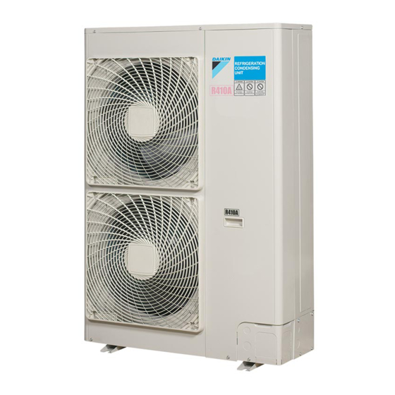
4 About the units This unit is intended for outdoor installation and aimed for air to air cooling applications. Specification LRMEQ3 LRMEQ4 LRLEQ3 LRLEQ4 Capacity (cooling) 5.90 kW 8.40 kW 2.78 kW 3.62 kW Ambient design –20~43°C DB (10.1 N·m) temperature (cooling) Capacity measured at the following conditions: ambient temperature 32°C, evaporating temperature –10°C, superheat 10 K. -
Page 9: Preparation
5 Preparation ▪ Expansion valve. Install an R410A expansion valve on each Preparing the installation site indoor unit. Insulate the feeler block of the expansion valve. Do NOT install the unit in places often used as work place. In case INFORMATION of construction works (e.g. -
Page 10: Additional Installation Site Requirements Of The Outdoor Unit In Cold Climates
5 Preparation In places with weak reception, keep distances of 3 m or more to ▪ deterioration of the operational capacity; avoid electromagnetic disturbance of other equipment and use ▪ disruption of operation due to decrease of low pressure or conduit tubes for power and transmission lines. -
Page 11: Securing Safety Against Refrigerant Leaks
5 Preparation Prevailing wind direction When there are no smaller room divisions: Air outlet 5.2.3 Securing safety against refrigerant leaks About safety against refrigerant leaks The installer and system specialist shall secure safety against leakage according to local regulations or standards. The following standards may be applicable if local regulations are not available. -
Page 12: Refrigerant Piping Requirements
5 Preparation Item Description Piping diameter Must comply with requirements. See "5.3.2 Refrigerant piping requirements" on Piping material page 12. Piping length and height difference Piping insulation If deteriorated, must be replaced. Must comply with requirements. See "6.6 To insulate the refrigerant piping" on page 21. Welded connections Must be checked for gas leaks. -
Page 13: To Select Refrigerant Branch Kits
5 Preparation When selecting an expansion valve for the load according to the D~F/d~f: Piping between piping branching and technical information of the expansion valve manufacturer, take into indoor unit account the subcooling ratio (K) for the liquid refrigerant in the table Use the same diameters as the connections (liquid, gas) on the below. -
Page 14: Installation
6 Installation The operation switch is located in the switchbox (see illustration ▪ Finishing the indoor installation. below). INFORMATION For installation of the indoor unit (mounting the indoor unit, connecting the refrigerant piping to the indoor unit, connecting the electrical wiring to the indoor unit …), see the installation manual of the indoor unit. -
Page 15: To Provide The Installation Structure
6 Installation 6.3.3 To provide the installation structure 6.3.5 To prevent the outdoor unit from falling over Check the strength and level of the installation ground so that the unit will not cause any operating vibration or noise. In case the unit is installed in places where strong wind can tilt the unit, take following measure: Fix the unit securely by means of foundation bolts in accordance with the foundation drawing. -
Page 16: Pipe Bending Guidelines
6 Installation ▪ Do NOT use flux when brazing copper-to-copper refrigerant NOTICE piping. Use phosphor copper brazing filler alloy (BCuP), which Take the following precautions on refrigerant piping into does not require flux. account: Flux has an extremely harmful influence on refrigerant piping ▪... -
Page 17: To Remove The Pinched Pipes
6 Installation 2 Insert a hexagon wrench into the stop valve and turn the stop valve counterclockwise. Cover (do NOT apply thread-locking fluid) Sealing part (do NOT apply thread-locking fluid) Screw thread with thread-locking fluid To handle the service port ▪... -
Page 18: Guidelines When Installing A Sight Glass
6 Installation 2 Connect the vacuuming/recovery unit through a manifold to the Where/how Install the sight glass before the dryer, as near service port of all stop valves. to the outdoor unit as possible. Install horizontally. p < p > R410A Pressure reducing valve a Sight glass... -
Page 19: Guidelines When Connecting Piping Branching
6 Installation ▪ Connect the gas piping accessories (c, d, e), and cut them to the required length (e1). This is necessary because the size of the gas stop valve is Ø15.9 while the piping between outdoor unit and first refrigerant branch kit is Ø19.1. Possibility 1: To the front Possibility 2: To the side 2 Choose a piping route (a, b, or c). -
Page 20: Checking The Refrigerant Piping
6 Installation All piping inside the unit has been factory tested for leaks. ≤30° Only field installed refrigerant piping needs to be checked. Therefore, make sure that all the outdoor unit stop valves are firmly closed before performing leak test or vacuum drying. NOTICE Joint for branching Make sure that all (field supplied) field piping valves are... -
Page 21: To Perform Vacuum Drying
6 Installation ▪ Make sure to insulate the connection piping and refrigerant piping To check for leaks: Vacuum leak test branching entirely. 1 Evacuate the system from the liquid and gas piping to ▪ Be sure to insulate the liquid and gas piping (for all units). –... -
Page 22: To Determine The Additional Refrigerant Amount
6 Installation NOTICE Inch piping Metric piping Piping Weight factor Piping Weight factor If the power of some units is turned off, the charging procedure cannot be finished properly. Ø6.4 mm 0.02 Ø6 mm 0.018 Ø9.5 mm 0.06 Ø10 mm 0.066 NOTICE Before starting charging procedures, check if the 7‑LEDs 6.7.4 To charge refrigerant display is as normal (see... - Page 23 6 Installation Result: The unit will start operation. 8 Set the target evaporating temperature with settings [2‑0] and [2‑1] (see "7.2.8 Mode 2: Field settings" on page 30). INFORMATION 9 Turn on the power of the indoor units. ▪ When a malfunction is detected during the procedure 10 Turn on the operation switch.
-
Page 24: Error Codes When Charging Refrigerant
6 Installation Screw thread with thread-locking fluid 6.7.5 Error codes when charging refrigerant P1 P2 INFORMATION When a malfunction occurs, X3M outputs a caution (C/C1) or warning (C/W1) signal, and the H2P LED on the main PCB lights up. If a malfunction occurs, close valve B and C immediately. Confirm F1 F2 the malfunction code and take corresponding action, "11.3 ... -
Page 25: Precautions When Connecting The Electrical Wiring
6 Installation Run signal WARNING Operation signal ▪ ONLY use copper wires. NOTICE ▪ Make sure the field wiring complies with the applicable The operation output P1/P2 of the outdoor unit must be legislation. connected to all solenoid valves that are installed upstream ▪... -
Page 26: Guidelines When Knocking Out Knockout Holes
6 Installation Tightening torques 6.8.4 Guidelines when knocking out knockout holes Wiring Screw size Tightening torque (N•m) NOTICE X1M: power supply wiring 2.2~2.7 Precautions when making knockout holes: (power supply + shielded ▪ Avoid damaging the casing. ground) ▪ After making the knockout holes, we recommend you X2M: remote operation M3.5 0.8~0.97... - Page 27 6 Installation 3N~ 50 Hz 6 Connect the wiring to the output signals terminal (X3M) as 380-415 V follows: L1 L2 L3 W1 R P1 P2 L1 L2 L3 Caution signal Warning signal Earth leakage circuit breaker Run signal Fuse Operation signal Power supply cable ▪...
-
Page 28: Finishing The Outdoor Unit Installation
7 Configuration Connecting to the When cables are routed from the unit, a INFORMATION frame protection sleeve for the conduits (PG It is important that all information in this chapter is read insertions) can be inserted at the knockout sequentially by the installer and that the system is hole. -
Page 29: To Access Mode 1 Or 2
7 Configuration TEST/ If the default situation is not displayed after 10~12 minutes, check MODE MASTER SLAVE L.N.O.P. DEMAND MULTI the malfunction code. Solve the malfunction code accordingly. Switching between modes Use BS1 to switch between the default situation, mode 1 and MODE RETURN TEST... -
Page 30: Mode 1 (And Default Situation): Monitoring Settings
7 Configuration 7.2.7 Mode 1 (and default situation): Monitoring Setting Value / Description settings [1‑14] For more information, see In mode 1 (and in default situation) you can read out some "11.3 Solving problems based on Shows the latest malfunction information. error codes" on page 34. -
Page 31: To Connect The Pc Configurator To The Outdoor Unit
8 Commissioning Setting Value Description (= binary) LRMEQ* LRLEQ* [2‑18] Correction of evaporating temperature (only (default) setting [2-13] applies) Low noise operation Adjustment of fan and compressor speed (only With this setting one of three low‑noise operation modes can be setting [2-17] applies) selected. -
Page 32: Checklist During Commissioning
9 Hand-over to the user 4 Check the sight glass of the outdoor unit. If the refrigerant is Fuses, circuit breakers, or protection devices NOT in sealing state, charge extra refrigerant, but do NOT Check that the fuses, circuit breakers, or the locally exceed 25% of the determined additional refrigerant amount installed protection devices are of the size and type (see... -
Page 33: 10 Maintenance And Service
10 Maintenance and service ▪ Make sure that the user has the printed documentation and ask him/her to keep it for future reference. Inform the user that he can find the complete documentation at the URL mentioned earlier in this manual. ▪... -
Page 34: Solving Problems Based On Error Codes
11 Troubleshooting DANGER: RISK OF ELECTROCUTION Action Display Select a malfunction. Possible malfunctions: [X×] WARNING ("X×" depends on the [1‑14] Latest malfunction: setting that you want Prevent hazards due to inadvertent resetting of the thermal to select.) cut-out: power to this appliance MUST NOT be supplied [1‑15] 2nd last malfunction: through an external switching device, such as a timer, or connected to a circuit that is regularly turned ON and OFF... -
Page 35: Disposal
12 Disposal Code Description Criteria Times of Output signal Cause Solution retry 3‑sensor error When 3 or more sensors detect abnormality Warning ▪ Faulty connection of sensor ▪ Connect the sensor properly ▪ Defective sensor or outdoor unit PCB ▪ Replace defective component High pressure switch failure No continuity of high pressure switch... -
Page 36: 13 Technical Data
13 Technical data Technical data A subset of the latest technical data is available on the regional Daikin website (publicly accessible). The full set of latest technical data is available on the Daikin extranet (authentication required). 13.1 Service space: Outdoor unit When mounting units side by side, the piping route must be to the front, to the back or downwards. - Page 37 13 Technical data Multiple rows of units ( b (mm) ≥100 ≥100 ≤½H b≥250 ½H <H ≤H b≥300 ≥100 ≥100 ≥100 >H ≥2000 ≥3000 ≥100 ≥200 ≥100 ≥1000 ≥600 ≥1500 Stacked units (max. 2 levels) ( ≥100 ≥100 ≥300 ≥1000 ≥100 ≥100 ≥100...
-
Page 38: Piping Diagram: Outdoor Unit
13 Technical data 13.2 Piping diagram: Outdoor unit S1NPH S1PH S1NPL 3D111393B Stop valve (gas) Stop valve (liquid) Filter Service port Check valve Maintenance stop valve Liquid receiver Heat exchanger Oil separator Distributor Double tube heat exchanger Propeller fan Sight glass Capillary tube Compressor Thermistor (air) -
Page 39: Wiring Diagram: Outdoor Unit
13 Technical data Connector 13.3 Wiring diagram: Outdoor unit Motor (compressor) The wiring diagram is delivered with the unit, located at the inside of Motor (fan) (upper) the service cover. Motor (fan) (lower) Symbols: NA (A1P) Connector English Translation P1, P2 Connector Symbols Symbols... -
Page 40: For The User
14 About the system For the user About the system Operation NOTICE 16.1 Operation range For future modifications or expansions of your system: Use the system in the following temperature ranges for safe and A full overview of allowable combinations (for future effective operation. -
Page 41: Maintenance After A Long Stop Period
19 Troubleshooting WARNING 18.1 Maintenance after a long stop period ▪ Do not modify, disassemble, remove, reinstall or repair the unit yourself as incorrect dismantling or installation E.g., at the beginning of the season. may cause an electric shock or fire. Contact your dealer. - Page 42 20 Relocation ▪ When the tone of operating noise changes. This noise is caused Malfunction Measure by the change of frequency. The system operates ▪ Check if air inlet or outlet of outdoor or but cooling is indoor unit is not blocked by obstacles. 19.1.4 Symptom: Dust comes out of the unit insufficient.
- Page 43 Optional equipment Equipment made or approved by Daikin that can be combined with the product according to the instructions in the accompanying documentation. Field supply Equipment NOT made by Daikin that can be combined with product according instructions accompanying documentation.
- Page 44 4P500362-1A 2018.09...