
Related Manuals for Daikin LFSLHS0200AXV1


Summary of Contents for Daikin LFSLHS0200AXV1
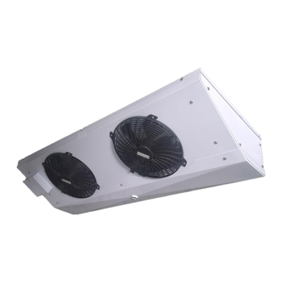
- Page 1 COMMERCIAL REFRIGERATION SLIM UNIT COOLER LOW TEMPERATURE OPERATING AND INSTALLATION MANUAL...
-
Page 2: Table Of Contents
TABLE OF CONTENTS Page Unit Information and Dimensions Nomenclature Product Features Unit Dimension General Specification General Capacity Table Unit Location and Mounting Unit Location Mounting Drain Trap Piping Installation Refrigerant Pipe Connection Vacuum and Leak test Drain Pipe Superheat Electrical Field Wiring Earth Wiring Wiring Diagram... -
Page 3: Nomenclature
Unit Category: C – Unit can be installed indoor or outdoor; R – Outdoor Unit; F – Indoor Unit; FS- Indoor Slim Unit Daikin low temperature refrigeration appliances Product features • Can be used with refrigerants R404A, R410A, R507A, R448A and R449A. -
Page 4: Unit Dimension
Unit Dimension L(mm) FL(mm) W(mm) H (mm) LFSLHS0200AXV1 1381 1313 1981 1913 LFSLHS0300AXV1 General Upon receive of the products, 1. Please ensure: • The pipework should shows no signs of damage • The fan/ fan motor terminal box are not cracked or showing signs of obvious damage •... -
Page 5: Specification
2 SPECIFICATION General (a) Low Temperature Model LFSLHS0200AXV1 LFSLHS0300AXV1 Capacity Sound dB(A) Pressure Level Power supply 220-240/1/50 220-240/1/50 (V/Ph/Hz) Size L/W/H 1381 x 510 x 238 1981 x 510 x 238 (mm/mm/mm) Weight (kg) 27.0 35.0 General Room Temperature (... -
Page 6: Capacity Table
Capacity Table (a) Low Temperature Refrigerant R404A Model LFSLHS0200AXV1 1.57 1.74 2.00 2.40 LFSLHS0300AXV1 2.34 2.67 3.00 3.33 Capacity Factor Refrigerant R404A R410A R507A R448A R449A Model LFSLHS0200AXV1 0.95 LFSLHS0300AXV1 0.95 *DT1=7K DT1=Air inlet temperature (Ta) - evaporating temperature at the outlet (Te) The nominal capacity according to EN 328 and calculated with refrigerant R404A. -
Page 7: Drain Trap
Drain Trap Drain pipes and traps must be at least same diameter as the drain fitting connection. See page 3 for details. Drain pan must be leveled to permit condensation from coil drain freely for the suitable depth and distance of drain trap installation. -
Page 8: Piping Installation
PIPING INSTALLATION Refrigerant pipe connection Refrigerant pipe connections should be installed in accordance with all the applicable codes and using good refrigeration practices. Suction lines should be properly insulated to prevent sweating and ensure only superheated vapor is returned to compressor suction. During brazing, the system should be purged with nitrogen first, to prevent oxidation. -
Page 9: Earth Wiring
Heater Location Heater slot available for defrost heaters and it had been inserted into the lower of cooling coil. It is advised to install thermal fuse (supplied by site) when the unit is used with defrost heater. The location of the thermal fuse should be appropriately located to have safety cut off when the heater is overheated. -
Page 10: Wiring Diagram
Wiring Diagram (a) LFSLHS0200AXV1 Page 8 0-UC 12-SEP 17-1... -
Page 11: Start-Up
LFSLHS0300AXV1 START UP Pre-start up After the installation is completed, a review of the following items should be performed before the system is placed into operation: Check electrical connections, fan motors, grills and all other fasteners for tightness. Be sure the thermostatic expansion valve bulb is properly located, strapped and insulated. -
Page 12: Preventative Maintenance
WARNING Please be aware that during electric defrost; the temperature of surrounding may rise dramatically. Kindly keep a safety distance away from the unit. Check the drain line and make sure drain line is clear and unit is aligned in all position to avoid overflow of condensation water. -
Page 13: Unit Decommissioning And Disposal
Accumulation of ice or Drain line plugged. Clean drain line. Make sure drain water in drain pan. line is insulated properly. Install the drain line with slope. Drain pipe does not have slope See page 5 for details. angle. Indoor unit not align or install Check unit installation and align in level at all directions. - Page 14 THIS PAGE IS LEFT BLANK INTENTIONALLY Page 12 0-UC 12-SEP 17-1...
- Page 15 THIS PAGE IS LEFT BLANK INTENTIONALLY Page 13 0-UC 12-SEP 17-1...