Table of Contents
Advertisement
Quick Links
Advertisement
Table of Contents

Related Manuals for Jet J-CK350-4


Summary of Contents for Jet J-CK350-4
- Page 1 This .pdf document is bookmarked Operating Instructions and Parts Manual Non-Ferrous Manual Cold Saw Models: J-CK350-2, J-CK350-4 427 New Sanford Road LaVergne, Tennessee 37086 Part No. M-414203 Ph.: 800-274-6848 Revision D 08/2019 www.jettools.com Copyright © 2017 JET...
-
Page 2: Warranty And Service
JET sells through distributors only. The specifications listed in JET printed materials and on official JET website are given as general information and are not binding. JET reserves the right to effect at any time, without prior notice, those alterations to parts, fittings, and accessory equipment which they may deem necessary for any reason whatsoever. -
Page 3: Table Of Contents
2.0 Table of Contents 1.0 Warranty and Service ..........................2 2.0 Table of Contents ........................... 3 3.0 IMPORTANT SAFETY INSTRUCTIONS ....................4 4.0 About this machine and manual ......................5 5.0 J-CK350 Features ..........................6 6.0 Specifications ............................ -
Page 4: Important Safety Instructions
Do not use this cold saw for other than its intended use. If used for other purposes, Provide for adequate space surrounding JET disclaims any real or implied warranty work area and non-glare, overhead lighting. and holds itself harmless from any injury that ... -
Page 5: About This Machine And Manual
If there are questions or comments about this product, please contact your local supplier or JET. JET can also be reached at our web site: www.jettools.com. -
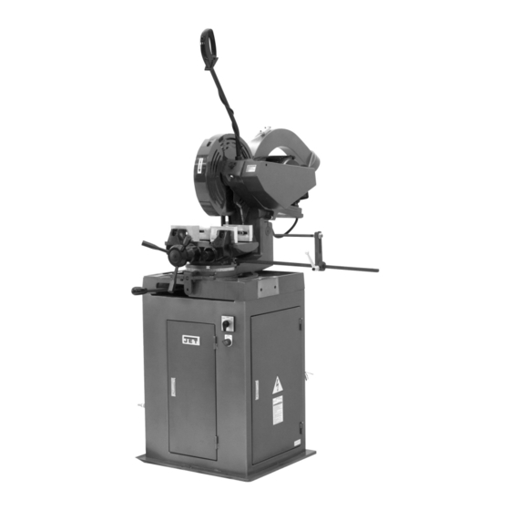
Page 6: J-Ck350 Features
5.0 J-CK350 Features 6.0 Specifications Model ................J-CK350-2 ..........J-CK350-4 Stock Number ..............414203 ............ 414207 Disc Blade Disc diameter ............14" (350mm) ........... 14" (350mm) Hole diameter ............1.3" (32mm) ..........1.3" (32mm) Blade thickness ............ 0.14" (3.4mm) ......... 0.14" (3.4mm) Cutting Speed Blade Speed (RPM) ........... -
Page 7: Features
7.0 Features 7.1 Miter Cutting Head The miter cutting head is the unit that cuts the material and consists of a cast iron base, blade support unit and guard, transmission unit, and motor. The depth of cut is set by adjusting the depth cut stop. -
Page 8: Installation
Figure 5 J-CK350-2 is rated at 220V. J-CK350-4 is rated at 440V. These machines are not supplied with a plug. Use a plug and outlet rated at least 20 amps. The circuit for the machine should also be protected by at least a 20 amp circuit breaker or fuse. -
Page 9: Operation
3. A detent mechanism locks the head in the -45º, 11.0 Operation 90º and +45º positions to prevent the head from rotating. For a miter position other than -45º, Before using the machine: 90º and +45º, press the lever (C) to release Check that safety devices, such as blade ... -
Page 10: Maintenance
12.5 Changing the Saw Blade 12.0 Maintenance The cold saw must not be 12.1 Maintenance Requirements connected power source when changing saw blades. Failure to comply may result in serious injury! All maintenance must be carried out with the power switched off. To change the saw blade: Failure to comply may result in serious 1. -
Page 11: Lubrication
12.7 Lubrication 12.9 Air Prep Unit For long life and trouble-free operation, it is Referring to Figure 14: essential that this machine be kept well Required Maintenance lubricated. The vise and leadscrew should be oiled daily. Pivot joints and bearings should be Check weekly. -
Page 12: Blades
resulting in poor cutting (same situation with soft 13.0 Blades materials), greater shearing stress and hence breakage of the blade. When using the J-CK350 cold saw, it is A larger pitch should be chosen when, as a important to select the correct type of blade for result of the shape of the piece to be cut, the the material to be cut. - Page 13 Teeth Shape ”C” TYPE SHARPENING (HZ) Coarse toothing with roughing tooth raked on both sides and non--raked finishing tooth – The roughing tooth is about 0.3 mm higher. Coarse toothing with roughing tooth and finishing tooth – Used in saws with pitch greater than or equal to 5 mm for cutting ferrous and non-ferrous materials with solid or solid-profiled Figure 19...
-
Page 14: Troubleshooting J-Ck350 Cold Saw
14.0 Troubleshooting J-CK350 Cold Saw 14.1 Blade and Cutting Problems Problem Probable Cause Solution Incorrect lubricant/coolant fluid Ensure proper coolant flow. Check the cutting speed, feed speed and air pressure Material too hard parameters and the type of blade you are using. With a new blade it is necessary to start cutting at half feeding speed. -
Page 15: Machine Fault & Operating Problems
Serial Number of your machine available when you call will allow us to serve you quickly and accurately. Non-proprietary parts, such as fasteners, can be found at local hardware stores, or may be ordered from JET. Some parts are shown for reference only, and may not be available individually. -
Page 16: Stand Assembly - Parts List
17 ..... FK350SX-649 ..Quick Coupler ..................1 18 ..... FK350-615 ....Transformer (440V only) ........AU-20DW(50/60Hz) ..1 ....FK350-615-2 .... Transformer (220V only) ................1 ....JET-92 ..... JET Logo (not shown) .......... 92x38mm ....1... -
Page 17: Stand Assembly - Exploded View
15.1.2 Stand Assembly – Exploded View... -
Page 18: Head Assembly - Parts List
15.2.1 Head Assembly – Parts List Index No. Part No. Description Size 1 ....J-CK350-201G ..Head Body ....................1 2 ....CK350-202 ....Spindle ..................... 1 3 ....CK350-203 ....Spindle Housing ..................1 4 ....CK350-204 ....Blade Flange .................... 1 6 .... -
Page 19: Head Assembly - Exploded View
15.2.2 Head Assembly – Exploded View... -
Page 20: Base Assembly - Parts List
15.3.1 Base Assembly – Parts List Index No. Part No. Description Size 1 ....FK350-101G .... Base ......................1 2 ....FK350-102G .... Hinge Body....................1 3 ....FK350-103G .... Locking Mount ..................1 4 ....FK350-104G .... Release Handle ..................1 5 .... -
Page 21: Base Assembly - Exploded View
15.3.2 Base Assembly – Exploded View... -
Page 22: Manual Vise Assembly - Parts List
15.4.1 Manual Vise Assembly – Parts List Index No. Part No. Description Size ....FK350-300 ....Complete Vise Assembly (includes index #1-32) ........1 ....J-FK350-301G ..Base ......................1 2 ....J-FK350-302 .... Front Vise Jaw (LH Thread) ..............1 3 .... -
Page 23: Manual Vise Assembly - Exploded View
15.4.2 Manual Vise Assembly – Exploded View... -
Page 24: Guard Assembly - Parts List
15.5.1 Guard Assembly – Parts List Index No. Part No. Description Size 1 ....J-CK350-401 .... Guard A ....................1 2 ....J-CK350-402 .... Guard B ....................1 3 ....J-CK350-403G ..Chute ......................1 4 ....J-CK350-404G ..Belt Guard ....................1 5 .... -
Page 25: Guard Assembly - Exploded View
15.5.2 Guard Assembly – Exploded View... -
Page 26: Ck350 Mist Coolant Assembly - Parts List
15.6.1 CK350 Mist Coolant Assembly – Parts List Index No. Part No. Description Size 1 ....CK350-701 ....Coolant Block ................... 1 2 ....CK350-702 ....Coolant Nipple ..................1 3 ....CK350-703 ....Coolant Nozzle ..................1 4 .... -
Page 27: Ck350 Mist Coolant Assembly - Exploded View
15.6.2 CK350 Mist Coolant Assembly – Exploded View... -
Page 28: In-Feed Table - Parts List And Exploded View
15.7.1 In-Feed Table – Parts List and Exploded View Index No. Part No. Description Size 1 ....FK350-701 ....Bracket ....................1 2 ....FK350-702 ....Stand ......................1 3 ....FK350-703 ....Leveling Foot ................... 2 4 .... -
Page 29: Out-Feed Table Parts List And Exploded View
15.8.1 Out-Feed Table Parts List and Exploded View Index No. Part No. Description Size 1 ....FK350-801 ....Guide Block ....................1 2 ....FK350-802 ....Guide Rail ....................1 3 ....TS-1502051 ..... Socket Head Cap Screw ........M5x20 ......8 4 .... -
Page 30: Stock Stop Assembly - Parts List And Exploded View
15.9.1 Stock Stop Assembly – Parts List and Exploded View Index No. Part No. Description Size 1 ....FK350-501 ....Block ......................1 2 ....FK350-502 ....Shaft ......................1 3 ....FK350-503 ....Stop Rod ....................1 4 .... -
Page 31: Wiring Diagram
16.0 Wiring Diagram... - Page 32 427 New Sanford Road LaVergne, Tennessee 37086 Phone: 800-274-6848 www.jettools.com...