Jet JWBS-15 Operating Instructions And Parts Manual
Woodworking band saws
Hide thumbs
Also See for JWBS-15:
- Operating instructions manual (56 pages) ,
- Operating instructions manual (54 pages)
Table of Contents
Advertisement
Operating Instructions and Parts Manual
Woodworking Band Saws
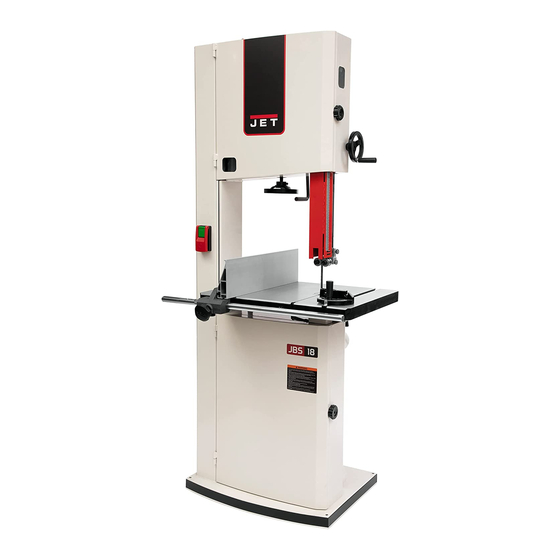
Model JWBS-15, JWBS-18, JWBS-20
For serial nos.:
JWBS-15: 17120226 and higher
JWBS-17: 18030001 and higher
JWBS-18: 17110021 and higher
JET
427 New Sanford Road
LaVergne, Tennessee 37086
Ph.: 800-274-6848
www.jettools.com
This .pdf document is bookmarked
JWBS-20 shown
Part No. M-714600
Edition 5 09/2018
Copyright © 2017 JET
Advertisement
Table of Contents

Related Manuals for Jet JWBS-15


Summary of Contents for Jet JWBS-15
- Page 1 This .pdf document is bookmarked Operating Instructions and Parts Manual Woodworking Band Saws Model JWBS-15, JWBS-18, JWBS-20 JWBS-20 shown 427 New Sanford Road LaVergne, Tennessee 37086 Part No. M-714600 Ph.: 800-274-6848 Edition 3 08/2017 www.jettools.com Copyright © 2017 JET...
- Page 1 This .pdf document is bookmarked Operating Instructions and Parts Manual Woodworking Band Saws Model JWBS-15, JWBS-18, JWBS-20 For serial nos.: JWBS-20 shown JWBS-15: 17120226 and higher JWBS-17: 18030001 and higher JWBS-18: 17110021 and higher 427 New Sanford Road LaVergne, Tennessee 37086 Part No.
-
Page 2: Important Safety Instructions
Do not use this band saw for other than its and other substances known to the State of intended use. If used for other purposes, JET California to cause cancer. Avoid inhaling dust disclaims any real or implied warranty and holds... -
Page 2: Important Safety Instructions
Do not use this band saw for other than its medication. intended use. If used for other purposes, JET disclaims any real or implied warranty and holds 21. Make certain switch is in OFF position before itself harmless from any injury that may result connecting machine to power supply. -
Page 3: Save These Instructions
29. Check damaged parts. Before further use of 36. Use recommended accessories; improper machine, a guard or other part that is damaged accessories may be hazardous. should be carefully checked to determine that it 37. Maintain tools with care. Keep blades sharp and will operate properly and perform its intended clean for best and safest performance. -
Page 3: Save These Instructions
29. Keep visitors a safe distance from work area. 39. Remove loose items and unnecessary work Keep children away. pieces from area before starting machine. 30. Make your workshop child proof with padlocks, 40. Keep hands out of line of saw blade. master switches or by removing starter keys. -
Page 4: Table Of Contents
6.0 Electrical connections ..........................13 6.1 GROUNDING INSTRUCTIONS ....................... 13 6.2 Models JWBS-15, JWBS-18 ........................13 6.3 Models JWBS-15-3, JWBS-18-3, JWBS-20-3, JWBS-20-5 ..............14 6.4 Circuit Information (all models) ......................... 14 6.5 Extension cords ............................14 7.0 Adjustments ..............................15 7.1 Aluminum resaw fence .......................... -
Page 4: Table Of Contents
6.0 Electrical connections ..........................13 6.1 GROUNDING INSTRUCTIONS ....................... 13 6.2 Models JWBS-15, JWBS-18 ........................13 6.3 Models JWBS-15-3, JWBS-18-3, JWBS-20-3, JWBS-20-5 ..............14 6.4 Circuit Information (all models) ......................... 14 6.5 Extension cords ............................14 7.0 Adjustments ..............................15 7.1 Aluminum resaw fence .......................... - Page 5 13.2.1 JWBS-15 Rip Fence Assembly – Exploded View ................36 13.2.2 JWBS-15 Rip Fence Assembly – Parts List ..................36 13.3.1 JWBS-15/18/20 Trunnion Support Bracket Assembly – Exploded View ..........37 13.3.2 JWBS-15/18/20 Trunnion Support Bracket Assembly – Parts List ............38 13.4.1 JWBS-15 Guide Bar Bracket Assembly –...
- Page 5 13.2.1 JWBS-15 Rip Fence Assembly – Exploded View ................36 13.2.2 JWBS-15 Rip Fence Assembly – Parts List ..................36 13.3.1 JWBS-15/18/20 Trunnion Support Bracket Assembly – Exploded View ..........37 13.3.2 JWBS-15/18/20 Trunnion Support Bracket Assembly – Parts List ............38 13.4.1 JWBS-15 Guide Bar Bracket Assembly –...
-
Page 6: About This Manual
Additional knowledge can be obtained from experienced users or trade articles. Whatever accepted methods are used, always make personal safety a priority. If there are questions or comments, please contact your local supplier or JET. JET can also be reached at our web site: www.jettools.com. -
Page 7: Specifications For Jwbs-15
4.1 Specifications for JWBS-15 Model number ..................JWBS-15 ......... JWBS-15-3 Stock number ..................714600 ..........714650 Band saw nominal size ................15 in............ 15 in. Motor and electricals: Motor type……………………………………………..totally-enclosed fan-cooled, induction, capacitor start ....Horsepower ..................1.75 HP ............ 3 HP Phase .................... -
Page 8: Specifications For Jwbs-18
4.2 Specifications for JWBS-18 Model number ..................JWBS-18 ......... JWBS-18-3 Stock number ..................714700 ..........714750 Band saw nominal size ................18 in............ 18 in. Motor and electricals: Motor type…………………………………………….. totally-enclosed fan-cooled, induction, capacitor start ....Horsepower ..................1.75 HP ............ 3 HP Phase .................... -
Page 9: Specifications For Jwbs-20
4.3 Specifications for JWBS-20 Model number .................. JWBS-20-3 ......... JWBS-20-5 Stock number ..................714800 ..........714850 Band saw nominal size ................20 in............ 20 in. Motor and electricals: Motor type…………………………………………….. totally-enclosed fan-cooled, induction, capacitor start ....Horsepower ................... 3 HP ............ 5 HP Phase .................... -
Page 10: Base Hole Centers
4.4 Base Hole Centers Figure 4-1: base hole centers (millimeters) -
Page 10: Base Hole Centers
4.4 Base Hole Centers Figure 4-1: base hole centers (millimeters) -
Page 11: Setup And Assembly
5.2 Tools required for assembly Read and understand the entire The tools listed below are not included but are contents of this manual before attempting required for assembly. assembly or operation. Failure to comply may cause serious injury. 2.5mm hex key 3mm hex key 5.0 Setup and assembly straight edge... -
Page 12: Installing Guide Rail
5.7 Installing guide rail Line up table to trunnions, and insert four hex cap screws with lock washers and flat washers Refer to Figure 5-6. (Figure 5-4). Hand tighten screws only. Attach guide rail (E) to table by inserting the two Check that table is parallel to blade: Move blade threaded studs into the table edge. -
Page 13: Miter Gauge
115 volt operation, but can be rewired for 230 volts. 115 Volt Operation The JWBS-15 and JWBS-18 Band Saw are for use on a nominal 115-V circuit, and have a grounded plug that looks like the plug illustrated in sketch A in Figure 6-1. -
Page 13: Miter Gauge
115 volt operation, but can be rewired for 230 volts. 115 Volt Operation The JWBS-15 and JWBS-18 Band Saw are for use on a nominal 115-V circuit, and have a grounded plug that looks like the plug illustrated in sketch A in Figure 6-1. -
Page 14: Models Jwbs-15-3, Jwbs-18-3, Jwbs-20-3, Jwbs-20-5
Figure 6-1 714800, JWBS-20-3 230 V 230 Volt Operation 714850, JWBS-20-5 230 V To convert the JWBS-15 or JWBS-18 from 115V to * Local codes take precedence over recommen- 230V, single phase operation, the following is dations. strongly recommended: Table 1... -
Page 15: Adjustments
7.0 Adjustments 7.1 Aluminum resaw fence Refer to Figures 7-1 and 7-2. Loosen knobs (A ) until lock bar protrudes enough on which to slide the aluminum fence plate from one end, as shown in Figure 7-1. Retighten knobs. Figure 7-3 7.3 Table tilt Refer to Figure 7-4. -
Page 15: Adjustments
7.0 Adjustments 7.1 Aluminum resaw fence Refer to Figures 7-1 and 7-2. Loosen knobs (A ) until lock bar protrudes enough on which to slide the aluminum fence plate from one end, as shown in Figure 7-1. Retighten knobs. Figure 7-3 7.3 Table tilt Refer to Figure 7-4. -
Page 16: Leveling Table Insert
If necessary, adjust pointer (G, Figure 15) to (If the teeth will not point down, no matter how zero. you orient blade, then blade is inside-out. Twist it into correct position and re-install it.) Figure 7-5 Figure 7-6 7.5 Leveling table insert Remove table insert to expose set screws in the table ledge. -
Page 17: Blade Tension
Move tension lever to Full Tension position. Place tension lever (K, Figure 7-9) in Full Tension position. Models JWBS-15 and JWBS-18: Turn adjust- ment screw (Figure 7-11) until gap between Set blade tension by rotating handwheel (L) screw and wheel shaft hinge is 1/8 to 3/16 in. -
Page 18: Overview - Bearing Adjustments
Make sure blade guides and other parts of time to observe blade in action through tracking machine will not interfere with blade movement. window. Use handwheel (N) to lower guide post until you 11. If further adjustments are needed, disconnect can see blade through tracking window (O, from power and repeat above procedure. -
Page 19: Upper Thrust Bearing
Loosen lock knob (D) and slide thrust bearing up to back of blade. Adjust thrust bearing until space between groove bottom and back edge of blade is approximately 0.015” (1/64”). Tighten lock knob (D). If lateral adjustment of bearing is needed to align groove with blade, loosen set screw (E) at front of bearing assembly, and shift bearing as needed. -
Page 20: Guide Post
7.11). Also, the table must be square with blade (see sect. 7.4). Loosen lock knob (L, Figure 7-20) and raise guide post to a high position. Confirm that guide post travels straight up and down, and guide bearings maintain their relationship to blade. -
Page 20: Guide Post
7.11). Also, the table must be square with blade (see sect. 7.4). Loosen lock knob (L, Figure 7-20) and raise guide post to a high position. Confirm that guide post travels straight up and down, and guide bearings maintain their relationship to blade. -
Page 21: Drive Belt Replacement And Tensioning
Tighten lock handle (A) to secure motor with moderate pressure on the belt halfway position. between the pulleys. An adequately tensioned belt will deflect about 1/2”. If tension isn’t strong enough, push down on motor. 11. Tighten motor lock handle (A). 12. -
Page 22: Operation
On 3- and 5-horsepower models, the on button will light up when it is pushed and saw is operating. (There is no light on 1-3/4 HP models.) The switch has a safety feature that prevents unauthorized or accidental starting of the machine. With band saw turned off, slide safety key (C, Figure 8-1) up and remove it from switch. -
Page 23: Resawing
Figure 9-5 Figure 9-3 9.6 Saw blade selection 9.4 Resawing Using the proper blade for the job will increase the Resawing is the process of slicing stock to reduce operating efficiency of your band saw, help reduce its thickness, or to produce boards that are thinner necessary saw maintenance, and improve your than original... -
Page 24: Shape
General rule: Use a blade that will have no fewer than 6 and no more than 12 teeth in the workpiece at any given time. Figure 9-8 Figure 9-6 9.11 Material 9.9 Shape Band saw blades can be made from different types Figure 9-7 shows common types of tooth shape. -
Page 24: Shape
General rule: Use a blade that will have no fewer than 6 and no more than 12 teeth in the workpiece at any given time. Figure 9-8 Figure 9-6 9.11 Material 9.9 Shape Band saw blades can be made from different types Figure 9-7 shows common types of tooth shape. -
Page 25: User-Maintenance
Clean band saw regularly to remove any resinous deposits and sawdust. Connect the band saw to a JET dust collection system of appropriate capacity. Keep miter slot, and guide bearings, clean and free of resin. -
Page 25: User-Maintenance
Clean band saw regularly to remove any resinous deposits and sawdust. Connect the band saw to a JET dust collection system of appropriate capacity. Keep miter slot, and guide bearings, clean and free of resin. -
Page 26: Blade Selection Guide
11.0 Blade Selection Guide Table 3 Identify the material and thickness of your workpiece. The chart will show the recommended PITCH, blade TYPE, and FEED RATE. Key: H – Hook L – Low S – Skip M – Medium R – Regular H –... -
Page 26: Blade Selection Guide
11.0 Blade Selection Guide Table 3 Identify the material and thickness of your workpiece. The chart will show the recommended PITCH, blade TYPE, and FEED RATE. Key: H – Hook L – Low S – Skip M – Medium R – Regular H –... -
Page 27: Troubleshooting Jwbs-Series Band Saws
Incorrect choice of saw blade for that Install correct blade. particular operation. Blade tension too light. Increase tension. Blade cannot be Tension spring is fatigued. Replace tension spring (contact JET tensioned properly. service representative). Incorrect blade tension or damaged Correct accordingly. blade. Blade binds in workpiece. -
Page 27: Troubleshooting Jwbs-Series Band Saws
Incorrect choice of saw blade for that Install correct blade. particular operation. Blade tension too light. Increase tension. Blade cannot be Tension spring is fatigued. Replace tension spring (contact JET tensioned properly. service representative). Incorrect blade tension or damaged Correct accordingly. blade. Blade binds in workpiece. - Page 28 Symptom Probable Cause Correction * Blade breaks Feed force too great. Reduce feed force. prematurely. Refer to blade selection chart; use finer Blade pitch too coarse. pitch blade. Check guide bearings correct Guide bearings not properly supporting position and signs of wear. Adjust or blade.
- Page 28 Symptom Probable Cause Correction * Blade breaks Feed force too great. Reduce feed force. prematurely. Refer to blade selection chart; use finer Blade pitch too coarse. pitch blade. Check guide bearings correct Guide bearings not properly supporting position and signs of wear. Adjust or blade.
-
Page 29: Mechanical And Electrical Problems
12.2 Mechanical and electrical problems Table 5 Symptom Probable Cause Correction * Machine will not No incoming power. Verify machine connections. start/restart or Cord damaged. Replace cord. repeatedly trips circuit One cause of overloading trips which are breaker or blows not electrical in nature is too heavy a cut. -
Page 30: Replacement Parts
13.0 Replacement Parts Replacement parts are listed on the following pages. To order parts or reach our service department, call 1-800- 274-6848 Monday through Friday, 8:00 a.m. to 5:00 p.m. CST. Having the Model Number and Serial Number of your machine available when you call will allow us to serve you quickly and accurately. -
Page 31: Jwbs-15 Assembly - Exploded View
13.1.1 JWBS-15 Assembly – Exploded View... -
Page 31: Jwbs-15 Assembly - Exploded View
13.1.1 JWBS-15 Assembly – Exploded View... -
Page 33: Jwbs-15 Assembly - Parts List
37 ....PM1800B-027-026 ..Retaining Ring ............E15 ....... 1 38 ....JWBS15-138 ..... Sponge ......................1 39 ....JET-138-R2000 ..Jet Logo ..............138x57mm ....1 40 ....JWBS15-140 ..... Sponge ..............760x10mm T=1 ..... 1 41 ....JWBS15-141 ..... Sponge ..............16x5mm T=2 ....1 42 .... -
Page 33: Jwbs-15 Assembly - Parts List
37 ....PM1800B-027-026 ..Retaining Ring ............E15 ....... 1 38 ....JWBS15-138 ..... Sponge ......................1 39 ....JET-138-R2000 ..Jet Logo ..............138x57mm ....1 40 ....JWBS15-140 ..... Sponge ..............760x10mm T=1 ..... 1 41 ....JWBS15-141 ..... Sponge ..............16x5mm T=2 ....1 42 .... - Page 34 Index No. Part No. Description Size 55 ....JWBS15-155 ..... Fixed Plate ..................... 1 56 ....TS-2361061 ....Spring Washer ............M6 ......... 2 57 ....TS-2246122 ....Socket Head Button Screw ........M6x12 ......2 58 ....PM1500-074 ....Tension Quick Release Lever Shaft .............. 1 59 ....
- Page 34 Index No. Part No. Description Size 55 ....JWBS15-155 ..... Fixed Plate ..................... 1 56 ....TS-2361061 ....Spring Washer ............M6 ......... 2 57 ....TS-2246122 ....Socket Head Button Screw ........M6x12 ......2 58 ....PM1500-074 ....Tension Quick Release Lever Shaft .............. 1 59 ....
- Page 35 Index No. Part No. Description Size ....JWBS18B-1101ACS . Centrifugal Switch (not shown) ..............1 102 .... PM1500-015 ....Motor Bracket Lock Handle ........M10x33 ......1 103 .... TS-1550071 ....Flat Washer ............. M10 ....... 1 104 .... JWBS15-1104 ... Motor Bracket ....................1 105 ....
- Page 35 Index No. Part No. Description Size ....JWBS18B-1101ACS . Centrifugal Switch (not shown) ..............1 102 .... PM1500-015 ....Motor Bracket Lock Handle ........M10x33 ......1 103 .... TS-1550071 ....Flat Washer ............. M10 ....... 1 104 .... JWBS15-1104 ... Motor Bracket ....................1 105 ....
-
Page 36: Jwbs-15 Rip Fence Assembly - Exploded View
13.2.1 JWBS-15 Rip Fence Assembly – Exploded View 13.2.2 JWBS-15 Rip Fence Assembly – Parts List Index No. Part No. Description Size ....JWBS15-1123 ... Rip Fence Assembly (#1 thru 18) ..............1 ....JWBS15-1123-201 ..Fence Body ....................1 2 .... -
Page 37: Jwbs-15/18/20 Trunnion Support Bracket Assembly - Exploded View
13.3.1 JWBS-15/18/20 Trunnion Support Bracket Assembly – Exploded View... -
Page 37: Jwbs-15/18/20 Trunnion Support Bracket Assembly - Exploded View
13.3.1 JWBS-15/18/20 Trunnion Support Bracket Assembly – Exploded View... -
Page 38: Jwbs-15/18/20 Trunnion Support Bracket Assembly - Parts List
13.3.2 JWBS-15/18/20 Trunnion Support Bracket Assembly – Parts List Index No Part No Description Size ....JWBS15-1138A ..Trunnion Support Bracket Assembly (#1 thru 34) ........... 1 ....TS-1550061 ....Flat Washer ............. M8 x Ø23 ...... 2 2 ....TS-2361081 ....Lock Washer ............M8 ......... 1 3 .... -
Page 39: Jwbs-15 Guide Bar Bracket Assembly - Exploded View
13.4.1 JWBS-15 Guide Bar Bracket Assembly – Exploded View 13.4.2 JWBS-15 Guide Bar Bracket Assembly – Parts List Index No Part No Description Size ....JWBS15-1120 ... Guide Bar Bracket Assembly (#1 thru 25) ............1 ....JWBS15-1120-401 ..Guide Bar....................... 1 2 .... -
Page 40: Jwbs-15 Upper Wheel Assembly - Exploded View
13.5.1 JWBS-15 Upper Wheel Assembly – Exploded View 13.5.2 JWBS-15 Upper Wheel Assembly – Parts List Index No Part No Description Size ....PM1500-019 ....Upper Wheel Assembly (#1 thru 5) ..............1 ....PM1500-019-01 ..Upper Wheel ............Dia.15 inches....1 2 .... -
Page 41: Jwbs-15 Lower Blade Guide Assembly - Exploded View
13.7.1 JWBS-15 Lower Blade Guide Assembly – Exploded View 13.7.2 JWBS-15 Lower Blade Guide Assembly – Parts List Index No Part No Description Size ....JWBS15-1137 ... Lower Blade Guide Assembly (#1 thru 10) ............1 ....PM1500-096-01 ..Lower Blade Guide Support ................1 2 .... -
Page 42: Jwbs-15 Upper Blade Guide Assembly - Exploded View
13.8.1 JWBS-15 Upper Blade Guide Assembly – Exploded View 13.8.2 JWBS-15 Upper Blade Guide Assembly – Parts List Index No Part No Description Size ....JWBS15-1121 ... Upper Blade Guide Assembly (#1 thru 17) ............1 ....PM1500-095-01 ..Upper Blade Guide Support ................1 2 .... -
Page 43: Jwbs-15/18/20 Miter Gauge Assembly - Exploded View
13.9.1 JWBS-15/18/20 Miter Gauge Assembly – Exploded View 13.9.2 JWBS-15/18/20 Miter Gauge Assembly – Parts List Index No Part No Description Size ....JWBS15-1122 ... Miter Gauge Assembly (#1 thru 9) ..............1 ....JWBS15-1122-701 ..Guide Bar....................... 1 2 .... -
Page 44: Jwbs-18 Bandsaw Assembly - Exploded View
13.10.1 JWBS-18 Bandsaw Assembly – Exploded View... -
Page 44: Jwbs-18 Bandsaw Assembly - Exploded View
13.10.1 JWBS-18 Bandsaw Assembly – Exploded View... -
Page 46: Jwbs-18 Bandsaw Assembly - Parts List
37 ....PM1800B-027-026 ..Retaining Ring (E) ........... E15 ....... 1 38 ....JWBS15-138 ..... Sponge ......................1 39 ....JET-138-R2000 ..Jet Logo ..............138x57mm ....1 40 ....JWBS15-140 ..... Sponge ..............760x10x1T mm ..... 1 41 ....JWBS15-141 ..... Sponge ..............16x5x2T mm ....1 42 .... -
Page 46: Jwbs-18 Bandsaw Assembly - Parts List
37 ....PM1800B-027-026 ..Retaining Ring (E) ........... E15 ....... 1 38 ....JWBS15-138 ..... Sponge ......................1 39 ....JET-138-R2000 ..Jet Logo ..............138x57mm ....1 40 ....JWBS15-140 ..... Sponge ..............760x10x1T mm ..... 1 41 ....JWBS15-141 ..... Sponge ..............16x5x2T mm ....1 42 .... - Page 47 Index No. Part No. Description Size 55 ....JWBS15-155 ..... Fixed Plate ..................... 1 56 ....TS-2361061 ....Spring Washer ............M6 ......... 2 57 ....TS-2246122 ....Socket Head Button Screw ........M6x12 ......2 58 ....PM1500-074 ....Tension Quick Release Lever Shaft .............. 1 59 ....
- Page 47 Index No. Part No. Description Size 55 ....JWBS15-155 ..... Fixed Plate ..................... 1 56 ....TS-2361061 ....Spring Washer ............M6 ......... 2 57 ....TS-2246122 ....Socket Head Button Screw ........M6x12 ......2 58 ....PM1500-074 ....Tension Quick Release Lever Shaft .............. 1 59 ....
- Page 48 Index No. Part No. Description Size ....JWBS18B-1101ACS . …Centrifugal Switch (not shown) ..............1 102 .... PM1500-015 ....Motor Bracket Lock Handle ........M10x33 ......1 103 .... TS-1550071 ....Flat Washer ............. M10 ....... 1 104 .... JWBS15-1104 ... Motor Bracket ....................1 105 ....
- Page 48 Index No. Part No. Description Size ....JWBS18B-1101ACS . …Centrifugal Switch (not shown) ..............1 102 .... PM1500-015 ....Motor Bracket Lock Handle ........M10x33 ......1 103 .... TS-1550071 ....Flat Washer ............. M10 ....... 1 104 .... JWBS15-1104 ... Motor Bracket ....................1 105 ....
-
Page 49: Jwbs-18/20 Rip Fence Assembly - Exploded View
13.11.1 JWBS-18/20 Rip Fence Assembly – Exploded View 13.11.2 JWBS-18/20 Rip Fence Assembly – Parts List Index No. Part No. Description Size ....JWBS18B-1128 ..Rip Fence Assembly (#1 thru 18) ..............1 ....JWBS15-1123-201 ..Fence Body ....................1 2 .... -
Page 50: Jwbs-18/20 Guide Bar Bracket Assembly - Exploded View
13.12.1 JWBS-18/20 Guide Bar Bracket Assembly – Exploded View 13.12.2 JWBS-18/20 Guide Bar Bracket Assembly – Parts List Index No Part No Description Size ....JWBS18B-1125 ..Guide Bar Bracket Assembly (#1 thru 28) ............1 ....JWBS18B-1125-401 . Guide Bar....................... 1 2 .... -
Page 51: Jwbs-18 Upper Wheel Assembly - Exploded View
13.13.1 JWBS-18 Upper Wheel Assembly – Exploded View 13.13.2 JWBS-18 Upper Wheel Assembly – Parts List Index No Part No Description Size ....PM1800B-018 ... Upper Wheel Assembly (#1 thru 6) ..............1 ....PM1800B-018-01 ..Upper Wheel ....................1 2 .... -
Page 52: Jwbs-18/20 Lower Blade Guide Assembly - Exploded View
13.15.1 JWBS-18/20 Lower Blade Guide Assembly – Exploded View 13.15.2 JWBS-18/20 Lower Blade Guide Assembly – Parts List Index No Part No Description Size ....JWBS18B-1142 ..Lower Blade Guide Assembly (#1 thru 12) ............1 ....PM1500-096-01 ..Lower Blade Guide Support ................1 2 .... -
Page 53: Jwbs-18/20 Upper Blade Guide Assembly - Exploded View
13.16.1 JWBS-18/20 Upper Blade Guide Assembly – Exploded View 13.16.2 JWBS-18/20 Upper Blade Guide Assembly – Parts List Index No Part No Description Size ....JWBS18B-1126 ..Upper Blade Guide Assembly (#1 thru 18) ............1 ....PM1500-095-01 ..Upper Blade Guide Support ................1 2 .... -
Page 54: Jwbs-20 Bandsaw Assembly - Exploded View
13.17.1 JWBS-20 Bandsaw Assembly – Exploded View... -
Page 54: Jwbs-20 Bandsaw Assembly - Exploded View
13.17.1 JWBS-20 Bandsaw Assembly – Exploded View... -
Page 56: Jwbs-20 Bandsaw Assembly - Parts List
23 ....TS-1503021 ....Socket Head Cap Screw ......... M6x10 ......2 24 ....JWBS20B-124 ... Upper Door ....................1 25 ....JET-138-R2000 ..Jet Logo ..............138x57mm ....1 26 ....TS-1501021 ....Socket Head Cap Screw ......... M4x8 ......8 27 .... -
Page 56: Jwbs-20 Bandsaw Assembly - Parts List
23 ....TS-1503021 ....Socket Head Cap Screw ......... M6x10 ......2 24 ....JWBS20B-124 ... Upper Door ....................1 25 ....JET-138-R2000 ..Jet Logo ..............138x57mm ....1 26 ....TS-1501021 ....Socket Head Cap Screw ......... M4x8 ......8 27 .... - Page 57 Index No. Part No. Description Size 54 ....PM1500-069 ....Cam ....................... 1 55 ....JWBS15-168 ..... Lock Knob ..............M10x53 ......1 56 ....PM1500-068 ....Lock Handle ............. M10 ....... 1 57 ....JWBS15-170 ..... Lock Knob ..............M10x25 ......1 58 ....
- Page 57 Index No. Part No. Description Size 54 ....PM1500-069 ....Cam ....................... 1 55 ....JWBS15-168 ..... Lock Knob ..............M10x53 ......1 56 ....PM1500-068 ....Lock Handle ............. M10 ....... 1 57 ....JWBS15-170 ..... Lock Knob ..............M10x25 ......1 58 ....
- Page 58 Index No. Part No. Description Size 98 ....PM1800B-093 ... Viewing Window .................... 1 99 ....TS-1521011 ....Set Screw ..............M4x4 ......2 100 .... TS-2246122 ....Socket Head Button Screw ........M6x12 ......1 101 .... TS-2361061 ....Spring Washer ............M6 ......... 1 102 ....
- Page 58 Index No. Part No. Description Size 98 ....PM1800B-093 ... Viewing Window .................... 1 99 ....TS-1521011 ....Set Screw ..............M4x4 ......2 100 .... TS-2246122 ....Socket Head Button Screw ........M6x12 ......1 101 .... TS-2361061 ....Spring Washer ............M6 ......... 1 102 ....
-
Page 59: Jwbs-20 Upper Wheel Assembly - Exploded View
13.18.1 JWBS-20 Upper Wheel Assembly – Exploded View 13.18.2 JWBS-20 Upper Wheel Assembly – Parts List Index No Part No Description Size ....PM2013B-018 ... Upper Wheel Assembly (#1 thru 5) ............... 1 1 ....PM2013B-018-01 ..Upper Wheel (Rubber Coating) ..............1 2 .... -
Page 60: Jwbs-20 Upper Wheel Sliding Bracket Assembly - Exploded View
13.20.1 JWBS-20 Upper Wheel Sliding Bracket Assembly – Exploded View... -
Page 60: Jwbs-20 Upper Wheel Sliding Bracket Assembly - Exploded View
13.20.1 JWBS-20 Upper Wheel Sliding Bracket Assembly – Exploded View... -
Page 61: Jwbs-20 Upper Wheel Sliding Bracket Assembly - Parts List
13.20.2 JWBS-20 Upper Wheel Sliding Bracket Assembly – Parts List Index No Part No Description Size 1 ....JWBS20B-112-801 ... Spring ......................1 2 ....JWBS20B-112-802 ... Bushing ......................1 3 ....JWBS20B-112-803 ... Plate....................... 1 4 ....TS-1540021 ....Hex Nut ..............M4 ......... 1 5 .... -
Page 62: Electrical Connections
14.0 Electrical Connections 14.1 Connections for 1.75HP (models 714600, 714700) PUSH BUTTON SWITCH 115V 1PH 230V 1PH (viewed from behind) START STOP GROUND Rewired to 115V GREEN GREEN START CAPACITOR WHITE 300MFD 250VAC CAPACITOR 40uF 250VAC GRAY MOTOR at 230V 1PH MOTOR at 115V 1PH... -
Page 63: Connections For 3Hp (Models 714650, 714750, 714800)
14.2 Connections for 3HP (models 714650, 714750, 714800) 1~ 230V POWER CORD 6-15P MAGNETIC SWITCH ASSEMBLY CONTROL PANEL WHITE BLACK BLACK BLACK WHITE YELLOW BLACK 230V BLACK WHITE GREEN START CAPACITOR 300MFD 250VAC CAPACITOR 60uF 300VAC... -
Page 64: Connections For 5Hp (Model 714850)
14.3 Connections for 5HP (model 714850) BLACK POWER WHITE SUPPLY JUNCTION BLOCK BLACK 1~ 230V WHITE MAGNETIC SWITCH ASSEMBLY CONTROL PANEL WHITE BLACK BLACK BLACK WHITE YELLOW BLACK 230V BLACK WHITE BLUE GREEN START CAPACITOR 300MFD BLUE 250VAC BLACK CAPACITOR BLACK 45uF 450VAC... -
Page 65: Warranty And Service
Accessories; Shop Tools; Warehouse & Dock products; Hand Tools; Air Tools NOTE: JET is a division of JPW Industries, Inc. References in this document to JET also apply to JPW Industries, Inc., or any of its successors in interest to the JET brand. -
Page 65: Warranty And Service
Accessories; Shop Tools; Warehouse & Dock products; Hand Tools; Air Tools NOTE: JET is a division of JPW Industries, Inc. References in this document to JET also apply to JPW Industries, Inc., or any of its successors in interest to the JET brand. - Page 66 This page intentionally left blank.
- Page 66 This page intentionally left blank.
- Page 67 This page intentionally left blank.
- Page 67 This page intentionally left blank.
- Page 68 427 New Sanford Road LaVergne, Tennessee 37086 Phone: 800-274-6848 www.jettools.com...
- Page 68 427 New Sanford Road LaVergne, Tennessee 37086 Phone: 800-274-6848 www.jettools.com...