Table of Contents
Advertisement
Advertisement
Table of Contents
Troubleshooting

Related Manuals for Jet J-3410


Summary of Contents for Jet J-3410
-
Page 1: Cover Page
This .pdf document is bookmarked Operating Instructions and Parts Manual 7x12 Horizontal Band Saw Models: J-3410, J-3410-2 427 New Sanford Road LaVergne, Tennessee 37086 Part No. M-414454 Ph.: 800-274-6848 Revision B3 01/2014 www.jettools.com Copyright © 2014 JET... -
Page 2: Warranty
NOTE: JET, Wilton and Powermatic are divisions of JPW Industries, Inc.. References in this document to JET, Wilton and/or Powermatic also apply to JPW Industries, Inc., or any of its successors in interest to the JET, Wilton and/or Powermatic brands. -
Page 3: Table Of Contents
Table of Contents Cover Page .......................... 1 Warranty ..........................2 Table of Contents ........................3 General Specifications ......................4 Warnings ..........................5-6 Using the Vise ........................7-9 Setting Blade Guides ......................9 Hydraulic Feed Control ......................10 Using Stock Stop ......................... 10 Changing Blade Speeds ..................... -
Page 4: General Specifications
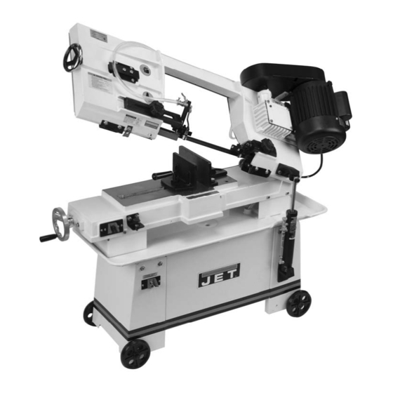
J-3410-2 414455 The JET Models J-3410 and J-3410-2 cut-off band The J-3410 and J-3410-2 come equipped with a cool- ant system which can greatly extend blade life and speed saws are designed for high production cut-off work. Four cutting speeds and a hydraulic feed control allows the effi- the cutting of a variety of materials which are best cut with cient cutting of virtually any material. -
Page 5: Warnings
- Always keep machine guards in place. results and full benefits from your machine. Used - Always put start switch in OFF“ position before properly, JET machinery is among the best in design plugging in machine. and safety. However, any machine used improperly When using machine: can be rendered inefficient and unsafe. -
Page 6: Safety Instructions On Sawing Systems
General Electrical Cautions 20.Some dust created by power sanding, sawing, This saw should be grounded in accordance with grinding, drilling and other construction activities the National Electrical Code and local codes and contains chemicals known to cause cancer, birth ordinances. This work should be done by a qualified defects or other reproductive harm. -
Page 7: Using The Vise
Operating Instructions The jaw closest to the left hand side of the table is Using the vise the locking jaw. This jaw clamps the workpiece against the The vise on the saw table has two jaws. The jaw stationary jaw to hold it securely for cutting. The locking closest to the right hand side of the table is the stationary jaw can pivot to conform to the angle of the work piece jaw. - Page 8 eventually catch the thrust shaft and allow you to open or Adjusting stationary jaw: close the locking jaw at its new lead screw position. When you slide the jaw to a new position, you can straight cuts see where the nearest lead screw groove is by looking through the slot above the lead screw.
-
Page 9: Setting The Blade Guides
Adjusting angles with the scale on the saw table There is a scale on the rear of the saw base which can be used to establish the angle of cut. 1. Raise the saw arm to full height and lock it in position with the quick shut-off valve. -
Page 10: Hydraulic Feed Control
Controlling the cut: Using the stock stop Hydraulic feed control for repeated cuts The weight of the saw arm typically provides all of the force needed to move the saw blade through the If you are cutting multiple pieces of stock, all to the workpiece. -
Page 11: Changing Blade Speeds
2. Never start a cut on a sharp edge. If the workpiece JET also can provide you with other blades. See the parts has a sharp edge, use a file to knock off the sharp edge listings for available blade types. -
Page 12: Angle Cuts
Right angle cuts -- Angle cutting 1. Raise the saw arm to full height and lock it in position single pieces of stock with the quick shut off valve. 2. Slide the vise open. 1. Raise the saw arm to its full up, open position. 3. - Page 13 Figure 8: Placing workpieces in the vise...
-
Page 14: Replacing Blades
Maintenance To adjust blade tracking: 1. Loosen the sliding plate draw block bolt slightly so the adjustment set screw will be able to move the draw block. 2. Turn the coolant pump switch OFF, if coolant is used. Replacing blades 3. -
Page 15: Blade Alignment Adjustments
Blade alignment adjustments When to adjust the The blade can suffer from several out-of-adjustment blade guides conditions. These conditions are shown in Figure 10. The blade guides, when installed at the factory, have been adjusted for maximum sawing effectiveness and, if not disturbed, damaged or worn, should require no field adjustment other than moving the guide brackets as needed to clear the workpieces being sawed. -
Page 16: Replacing Blade Guides And Support Components
parallel to the stationary jaw, no further parallelism Replacing blade guide adjustment is required. However, if the blade is at an angle to the jaw, determine which bearing set you are and support components going to move and the direction in which you need to All component parts are secured with nuts, bolts, move it. -
Page 17: Adjusting Blade Vertical
Adjusting blade vertical: Test cutting to verify The blade guide bearing seat can rotate as needed to adjustment accuracy make the blade vertical to the saw table. Follow these instructions. Test cuts can be used to determine whether or not 1. -
Page 18: Adjusting Guide Bearings
Adjusting guide bearings Replacing guide bearings There are eight side blade guide/support bearings. 1. Remove the blade as outlined in steps 1 through 6 of These bearings are installed in the bearing seat, and the Replacing blades. seat is attached to the sliding adjustment bracket. 2. -
Page 19: Replacing The Drive Wheel
Replacing the drive wheel Replacing idler wheel 1. Complete steps 1 through 6 in Replacing blades. or bearings 2. Remove the snap ring which secures the lower wheel to the gearbox output shaft. 1. Complete steps 1 through 6 in Replacing blades. 3. -
Page 20: Servicing The Hydraulic Control Cylinder
jack oil for the hydraulic fluid. Servicing the hydraulic 25. Install the top cap on the piston rod and slide it into the cylinder, flush with the bottom snap ring. Again, a control cylinder slight twisting motion will help ease the top cap into Over a long period of service the hydraulic control positon. -
Page 21: Machine Set-Up
To change the If ordered with the coolant kit, the kit is typically installed at the JET factory. However, if the kit is ordered operating voltage separately by you, it must be installed by a set-up mechanic, so instructions for this task are included in this 1. -
Page 22: Installing The Coolant Kit
Installing the coolant kit Adjusting the horizontal stop 1. Install the baffle in the tank so the pump is held at one and motor switch end of the tank. 2. Put the tank and pump assembly in the flanges which The horizontal stop and motor switch are located on hold it in the saw base. -
Page 23: Troubleshooting
Troubleshooting Problem Probable cause Potential solutions 1. Use more pressure to tighten vise. Excessive Material loose in the vise 2. Check stationary jaw pivot and lock bolts for tightness. blade 3. Check quick release handle nut for excessive tightness breakage -- nut should be just tight enough to keep adjustable jaw from tilting when tightening. -
Page 24: Troubleshooting
Troubleshooting Feed pressure too great 1. Observe chip formation to be sure cutting is efficient. 1. Adjust guide bearings according to instruction in this Guide bearings not adjusted properly manual. Inadequate blade tension 1. Increase blade tension so blade does not slip on the wheels. -
Page 25: Replacement Parts And Breakdowns
This section provides exploded view illustrations that show the replacement parts for the Model J-3410 and J-3410-2, 7" x 12" Horizontal Cut-Off Band Saw. Also provided are parts listings that provide part number and description. The item numbers shown on the illustration relate to the item number in the facing parts listing. - Page 27 Parts List - Saw Head Ref. Ref. Qty. Qty. Description Description Part.no. Part.no. J-5710011 Pulley cover 5710551 Bearing pin 5710021 Motor pulley 5710561 Eccentric shaft assy. 5710041 HH screw 5/16X1 51-1 5517504 Center shaft assy. J-5710051 Motor 3/4 HP 115V 1PH 5710571 Brush J-5710061 Motor mount plate assy.
- Page 28 Exploded View - Saw Base...
- Page 29 Parts List - Saw Base Ref. Ref. Part no. Description Part no. Description Qty. Qty. 121 5711341 Stock stop rod 5710211 Spring washer 3/8 5517530 HH screw 5/16x3/4 5710221 HH screw 5/16x3/4 5711371 Horizontal stop screw support 20-1 5517520 HH screw 5/16x1/2 5711381 Horizontal stop screw 5517521...
- Page 30 Parts List - Hydraulic Cylinder Ref. Part no. Description Qty. 5517547 Dust cover 5517548 Retaining ring 5517549 Oil-seal 5517550 Oil-piston 5517551 O-ring 5517552 Cylinder body 5517553 Oil pressure regulator 5517554 Oil duct...
- Page 32 427 New Sanford Road LaVergne, Tennessee 37086 Ph: 800-274-6848 www.jetttools.com...