
Related Manuals for Hawking HW17ACM


Summary of Contents for Hawking HW17ACM
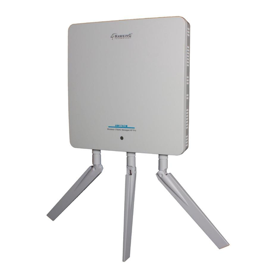
- Page 1 Wireless-1750AC Managed Access Point Pro HW17ACM website www.hawkingtech.com USER’S MANUAL e-mail techsupport@hawkingtech.com © COPYRIGHT 2017 HAWKING TECHNOLOGIES,INC. ALL RIGHTS RESERVED.
- Page 2 COPYRIGHT Copyright ©2017 by Hawking Technologies. All rights reserved. No part of this publication may be reproduced, transmitted, transcribed, stored in a retrieval system, or translated into any language or computer language, in any form or by any means, electronic, mechanical, magnetic, optical, chemical,...
- Page 3 Federal Communication Commission Interference Statement FCC Part 15 This equipment has been tested and found to comply with the limits for a Class B digital device, pursuant to Part 15 of FCC Rules. These limits are designed to provide reasonable protection against harmful interference in a residential installation.
- Page 4 This equipment complies with FCC radiation exposure set forth for an uncontrolled environment. In order to avoid the possibility of exceeding the FCC radio frequency exposure limits, human proximity to the antenna shall not be less than 20cm (8 inches) during normal operation. The antenna(s) used for this transmitter must not be co-located or operating in conjunction with any other antenna or transmitter.
-
Page 5: Table Of Contents
CONTENTS Chapter 1 - Product Information..............2 1-1. Package Contents ..........................2 1-2. System Requirements........................2 1-3. Hardware Overview .......................... 3 1-4. LED Status ............................4 1-5. Reset ..............................5 I-6. Magnetic Wall Mount ......................... 6 I-7. Console ..............................7 1-8. - Page 6 4-4-2. Date and Time ........................64 4-4-3. Syslog Server ........................66 4-4-4. I’m Here ..........................67 4-5. Advanced ............................68 4-5-1. LED Settings ......................... 68 4-5-2. Update Firmware ........................ 69 4-5-3. Save/Restore Settings ......................71 4-5-4. Factory Default ........................73 4-5-5.
-
Page 7: Chapter 1 - Product Information
Chapter 1 - Product Information 1-1. Package Contents HW17ACM Quick Installation Guide 3x 2dBi Omnidirectional Dual Band Power Cord Antennas Power Adapter 12V/4A Magnetic Wall Mount x 2 screws 1-2. System Requirements Existing cable/DSL modem & router Computer with web browser for access point configuration... -
Page 8: Hardware Overview
1-3. Hardware Overview C LAN 2 E Eject G Reset I On/Off A 12V DC IN D USB Port F Console H WPS B LANx 1 (PoE) 12V DC port to connect the power adapter LAN port with Power over Ethernet (PoE PD, IN) LAN port with Power over Ethernet (PoE PSE, OUT) USB Port for system log Eject an attached USB device... -
Page 9: Led Status
1-4. LED Status LED Status Description The access point is off. Blue The access point is on. Amber The access point is starting up. -
Page 10: Reset
1-5. Reset If you experience problems with your access point, you can reset the device back to its factory settings. This resets all settings back to default. Press and hold the reset button on the access point for at least 20 seconds then release the button. You may need to use a pin or similar sharp object to push the reset button. -
Page 11: I-6. Magnetic Wall Mount
I-6. Magnetic Wall Mount The access point includes a magnetic wall mount which requires some assembly. Attach the two magnetic wall mount strips to your wall using the included screws, as shown below. Press the back of your access point firmly against the two wall mounted magnetic strips, with the access point in the correct position, upright orientation as displayed above. -
Page 12: I-7. Console
I-7. Console The access point can be configured via the “Console” port located on the access point’s side panel using a terminal-emulation program (e.g. HyperTerminal). Use the following configuration settings for terminal-emulation programs: Baud Rate 115200 Data 8 bit Parity None Stop 1 bit... -
Page 13: Safety Information
1-8. Safety Information In order to ensure the safe operation of the device and its users, please read and act in accordance with the following safety instructions. 1. The access point is designed for indoor use only; do not place the access point outdoors. 2. -
Page 14: Chapter 2 - Quick Setup
Chapter 2 - Quick Setup Your access point can be up and running in just a few minutes. This quick installation guide will help to set up your access point and configure its basic settings. Please follow the instructions in the chapters below: 2-1. - Page 15 You will be prompted for a username and password. Enter the default username “admin” and the default password “1234”. You will arrive the “Quick Setup” screen shown below.
- Page 16 Next, please follow the instructions below in 2-2. Quick Setup to configure the access point’s basic settings. For more advanced configurations, please refer to Chapter 4. Browser Based Configuration Interface.
-
Page 17: Quick Setup Settings
2-2. Quick Setup Settings The instructions below will help you to configure the following basic settings of the access point: 2.4GHz & 5GHz SSID LAN IP Address LAN IP Address 2.4GHz & 5GHz SSID Security It is recommended you configure these settings before using the access point. To change the SSID of your access point’s 2.4GHz wireless network(s), go to “2.4GHz Basic Settings”. - Page 18 To change the access point’s LAN IP address, go to “LAN-side IP Address” and you will see the screen below. Enter the IP address settings you wish to use for your access point. You can use a dynamic (DHCP) or static IP address, depending on your network environment.
- Page 19 Key” depending on your choice, then click “Apply”. Hawking recommends at least WPA/WPA2 security. If using multiple SSIDs, specify which SSID to configure using the “SSID” drop down menu. Go to “Wireless Setting” > “5GHz 11ac 11an” and repeat steps 5 for the access point’s 5GHz wireless network.
-
Page 20: Wi-Fi Protected Setup (Wps)
2-3 Wi-Fi Protected Setup (WPS) Wi-Fi Protected Setup is a simple way to establish connections between WPS compatible devices. You can use the WPS button to establish a connection between the access point and a WPS-compatible wireless device/client. Press and hold the WPS/Reset button on the back of the access point for 2 seconds. Within two minutes, activate WPS on your WPS-compatible wireless device. -
Page 21: Chapter 3 - Hardware Installation
Chapter 3 - Hardware Installation 3-1. Connecting the access point to a router or PoE switch Connect a router or PoE switch to the access point’s LAN 1 port using an Ethernet cable. PoE switches must be connected to the access point’s LAN 1 port. If you are using a router, then connect the power adapter to the access point’s 12V DC port and pug the power adapter into a power supply. -
Page 22: Chapter 4 - Browser Based Configuration Interface
Chapter 4 - Browser Based Configuration Interface The browser-based configuration interface enables you to configure the access point’s advanced features. The device features a range of advanced functions such as MAC filtering, MAC RADIUS authentication, VLAN configurations, up to 32 SSIDs and many more. To access the browser based configuration interface: Connect a computer to your access point using an Ethernet cable. - Page 23 Use the menu across the top and down the left side to navigate. Click “Apply” to save changes and reload the access point, or “Cancel” to cancel changes. Please wait a few seconds for the access point to reload after you “Apply” changes, as shown below.
-
Page 24: Information
4-1. Information Screenshots displayed are examples. The information shown on your screen will vary depending on your configuration. 4-1-1. System Information The “System Information” page displays basic system information about the access point. - Page 26 System Model Displays the model number of the access point. Product Name Displays the product name for reference, which consists of “AP” plus the MAC address. Uptime Displays the total time since the device was turned on. Boot From Displays information for the booted hardware, booted from either USB or internal memory Version Displays the firmware version.
- Page 27 Authentication Method Displays the authentication method for the specified SSID. See 4-3. Wireless Settings Encryption Type Displays the encryption type for the specified SSID. See 4-3. Wireless Settings VLAN ID Displays the VLAN ID for the specified SSID. See 4-2-3. VLAN Additional Authentication Displays the additional authentication type for the specified SSID.
-
Page 28: Wireless Clients
4-1-2. Wireless Clients The “Wireless Clients” page displays information about all wireless clients connected to the access point on the 2.4GHz or 5GHz frequency. Refresh time Auto Refresh Time Select a time interval for the client table list to automatically refresh. - Page 29 Idle Time Client idle time is the time for which the client has not transmitted any data packets i.e. is idle. Vendor The vendor of the client’s wireless adapter is displayed here.
-
Page 30: Wireless Monitor
4-1-3. Wireless Monitor Wireless Monitor is a tool built into the access point to scan and monitor the surrounding wireless environment. Select a frequency and click “Scan” to display a list of all SSIDs within range along with relevant details for each SSID. Wireless Monitor Site Survey Select which frequency (or both) to scan, and click “Scan”... - Page 31 Type Displays the 802.11 wireless networking standard(s) of the specified SSID. Vendor Displays the vendor of the wireless router/access point for the specified SSID.
-
Page 32: Log
4-1-4. Log The system log displays system operation information such as up time and connection processes. This information is useful for network administrators. When the log is full, old entries are overwritten. Save Click to save the log as a file on your local computer. Clear Clear all log entries. - Page 33 The following information/events are recorded by the log: USB Mount & unmount Wireless Client Connected & disconnected Key exchange success & fail Authentication Authentication fail or successful. Association Success or fail WPS M1 - M8 messages WPS success ...
- Page 34 ADT...
-
Page 35: Network Settings
4-2. Network Settings Screenshots displayed are examples. The information shown on your screen will vary depending on your configuration. 4-2-1. LAN-Side IP Address The “LAN-side IP address” page allows you to configure your access point on your Local Area Network (LAN). You can enable the access point to dynamically receive an IP address from your router’s DHCP server or you can specify a static IP address for your access point, as well as configure DNS servers. - Page 36 Subnet Mask Specify a subnet mask. The default value is 255.255.255.0 Default Gateway For DHCP users, select “From DHCP” to get default gateway from your DHCP server or “User-Defined” to enter a gateway manually. For static IP users, the default value is blank. DHCP users can select to get DNS servers’...
-
Page 37: Lan Port
4-2-2. LAN Port The “LAN Port” page allows you to configure the settings for your access point’s two wired LAN (Ethernet) ports. Wired LAN Port Identifies LAN port 1. Enable Enable/disable LAN port. Speed & Duplex Select a speed & duplex type for LAN port, or use the “Auto” value. -
Page 38: Vlan
4-2-3. VLAN The “VLAN” (Virtual Local Area Network) enables you to configure VLAN settings. A VLAN is a local area network which maps workstations virtually instead of physically and allows you to group together or isolate users from each other. VLAN IDs 1 – 4094 are supported. VLAN IDs in the range 1 –... -
Page 39: Wireless Settings
4-3. Wireless Settings Screenshots displayed are examples. The information shown on your screen will vary depending on your configuration. 4-3-1. 2.4GHz 11bgn The “2.4GHz 11bgn” menu allows you to view and configure information for your access point’s 2.4GHz wireless network across four categories: Basic, Advanced, Security and WDS. - Page 40 4-3-1-1. Basic The “Basic” screen displays basic settings for your access point’s 2.4GHz Wi-Fi network (s).
- Page 41 Wireless Enable or disable the access point’s 2.4GHz wireless radio. When disabled, no 2.4GHz SSIDs will be active. Band Select the wireless standard used for the access point. Combinations of 802.11b, 802.11g & 802.11n can be selected. Enable SSID Number Select how many SSIDs to enable for the 2.4GHz frequency from the drop down menu.
- Page 42 Channel Select a wireless channel from 1 – 11. Channel Bandwidth Set the channel bandwidth: 20MHz (lower performance but less interference), 40MHz (higher performance but potentially higher interference) or Auto (automatically select based on interference level). BSS BasicRate Set Set a Basic Service Set (BSS) rate: this is a series of rates to control communication frames for wireless clients.
- Page 43 4-3-1-2. Advanced These settings are for experienced users only. Please do not change any of the values on this page unless you are already familiar with these functions. Changing these settings can adversely affect the performance of your access point. Contention Slot Select “Short”...
- Page 44 802.11n Protection Enable/disable 802.11n protection, which increases reliability but reduces bandwidth (clients will send Request to Send (RTS) to access point, and access point will broadcast Clear to Send (CTS), before a packet is sent from client.) DTIM Period Set the DTIM (delivery traffic indication message) period value of the wireless radio.
- Page 45 4-3-1-3. Security The access point provides various security options (wireless data encryption). When data is encrypted, information transmitted wirelessly cannot be read by anyone who does not know the correct encryption key. It’s essential to configure wireless security in order to prevent unauthorised access to your network.
- Page 46 SSID Selection Select which SSID to configure security settings for. Broadcast SSID Enable or disable SSID broadcast. When enabled, the SSID will be visible to clients as an available Wi-Fi network. When disabled, the SSID will not be visible as an available Wi-Fi network to clients –...
- Page 47 4-3-1-3-2. WEP WEP (Wired Equivalent Privacy) is a basic encryption type. For a higher level of security consider using WPA encryption. Key Length Select 64-bit or 128-bit. 128-bit is more secure than 64-bit and is recommended. Key Type Choose from “ASCII” (any alphanumerical character 0-9, a-z and A-Z) or “Hex”...
- Page 48 WPA Type Select from WPA/WPA2 Mixed Mode-EAP, WPA2-EAP or WPA- EAP. Encryption Select “TKIP/AES Mixed Mode” or “AES” encryption type. Key Renewal Interval Specify a frequency for key renewal in minutes. WPA-EAP must be disabled to use MAC-RADIUS authentication. 4-3-1-3-6. Additional Authentication Additional wireless authentication methods can also be used: MAC Address Filter Restrict wireless clients access based on MAC address specified in the MAC filter table.
- Page 49 4-3-1-4. WDS Wireless Distribution System (WDS) can bridge/repeat access points together in an extended network. WDS settings can be configured as shown below. When using WDS, configure the IP address of each access point to be in the same subnet and ensure there is only one active DHCP server among connected access points, preferably on the WAN side.
- Page 50 2.4GHz WDS Functionality Select “WDS with AP” to use WDS with access point or “Dedicated WDS” to use WDS and also block communication with regular wireless clients. When WDS is used, each access point should be configured with corresponding MAC addresses, wireless channel and wireless encryption method.
-
Page 51: 5Ghz 11Ac 11An
4-3-2. 5GHz 11ac 11an The “5GHz 11ac 11an” menu allows you to view and configure information for your access point’s 5GHz wireless network across four categories: Basic, Advanced, Security and WDS. 4-3-2-1. Basic The “Basic” screen displays basic settings for your access point’s 5GHz Wi-Fi network (s). - Page 52 VLAN ID Specify a VLAN ID for each SSID. Auto Channel Enable/disable auto channel selection. Auto channel selection will automatically set the wireless channel for the access point’s 5GHz frequency based on availability and potential interference. When disabled, select a channel manually as shown in the next table.
- Page 53 Guard Interval Set the guard interval. A shorter interval can improve performance. 802.11n Protection Enable/disable 802.11n protection, which increases reliability but reduces bandwidth (clients will send Request to Send (RTS) to access point, and access point will broadcast Clear to Send (CTS), before a packet is sent from client.) DTIM Period Set the DTIM (delivery traffic indication message) period value...
- Page 54 4-3-2-3. Security The access point provides various security options (wireless data encryption). When data is encrypted, information transmitted wirelessly cannot be read by anyone who does not know the correct encryption key. It’s essential to configure wireless security in order to prevent unauthorised access to your network.
- Page 55 Load Balancing Load balancing limits the number of wireless clients connected to an SSID. Set a load balancing value (maximum 50). Authentication Method Select an authentication method from the drop down menu and refer to the information below appropriate for your method.
- Page 56 4-3-2-4. WDS Wireless Distribution System (WDS) can bridge/repeat access points together in an extended network. WDS settings can be configured as shown below. When using WDS, configure the IP address of each access point to be in the same subnet and ensure there is only one active DHCP server among connected access points, preferably on the WAN side.
- Page 57 WDS Functionality Select “WDS with AP” to use WDS with access point or “Dedicated WDS” to use WDS and also block communication with regular wireless clients. When WDS is used, each access point should be configured with corresponding MAC addresses, wireless channel and wireless encryption method. Local MAC Address Displays the MAC address of your access point.
-
Page 58: Wps
4-3-3. WPS Wi-Fi Protected Setup is a simple way to establish connections between WPS compatible devices. WPS can be activated on compatible devices by pushing a WPS button on the device or from within the device’s firmware/configuration interface (known as PBC or “Push Button Configuration”). When WPS is activated in the correct manner and at the correct time for two compatible devices, they will automatically connect. - Page 59 WPS by PIN Enter the PIN code of another WPS device and click “Start” to attempt to establish a WPS connection for approximately 2 minutes. WPS Status WPS security status is displayed here. Click “Release” to clear the existing status.
-
Page 60: Radius
4-3-4. RADIUS The RADIUS sub menu allows you to configure the access point’s RADIUS server settings, categorized into three submenus: RADIUS settings, Internal Server and RADIUS accounts. A RADIUS server provides user-based authentication to improve security and offer wireless client control – users can be authenticated before gaining access to a network. - Page 61 RADIUS Type Select “Internal” to use the access point’s built-in RADIUS server or “external” to use an external RADIUS server. RADIUS Server Enter the RADIUS server host IP address. Authentication Port Set the UDP port used in the authentication protocol of the RADIUS server.
-
Page 62: Mac Filter
4-3-5. MAC Filter Mac filtering is a security feature that can help to prevent unauthorized users from connecting to your access point. This function allows you to define a list of network devices permitted to connect to the access point. Devices are each identified by their unique MAC address. - Page 63 separated with commas, e.g. ‘aa-bb-cc-dd-ee-ff,aa-bb-cc-dd- ee-gg’ Click “Add” to add the MAC address to the MAC address filtering table. Reset Clear all fields. MAC address entries will be listed in the “MAC Address Filtering Table”. Select an entry using the “Select” checkbox.
-
Page 64: Wmm
4-3-6. WMM Wi-Fi Multimedia (WMM) is a Wi-Fi Alliance interoperability certification based on the IEEE 802.11e standard, which provides Quality of Service (QoS) features to IEEE 802.11 networks. WMM prioritizes traffic according to four categories: background, best effort, video and voice. Configuring WMM consists of adjusting parameters on queues for different categories of wireless traffic. - Page 65 CWMin Minimum Contention Window (milliseconds): This value is input to the initial random backoff wait time algorithm for retry of a data frame transmission. The backoff wait time will be generated between 0 and this value. If the frame is not sent, the random backoff value is doubled until the value reaches the number defined by CWMax (below).
-
Page 66: Management
4-4. Management Screenshots displayed are examples. The information shown on your screen will vary depending on your configuration. 4-4-1. Admin You can change the password used to login to the browser-based configuration interface here. It is advised to do so for security purposes. If you change the administrator password, please make a note of the new password. - Page 67 Account to Manage This Device Administrator Name Set the access point’s administrator name. This is used to log in to the browser based configuration interface and must be between 4-16 alphanumeric characters (case sensitive). Administrator Password Set the access point’s administrator password. This is used to log in to the browser based configuration interface and must be between 4-32 alphanumeric characters (case sensitive).
- Page 68 Management Protocol Check/uncheck the boxes to enable/disable specified management interfaces (see below). When SNMP is enabled, complete the SNMP fields below. SNMP Version Select SNMP version appropriate for your SNMP manager. SNMP Get Community Enter an SNMP Get Community name for verification with the SNMP manager for SNMP-GET requests.
-
Page 69: Date And Time
4-4-2. Date and Time You can configure the time zone settings of your access point here. The date and time of the device can be configured manually or can be synchronized with a time server. Date and Time Settings Local Time Set the access point’s date and time manually using the drop down menus. - Page 70 Time Zone Time Zone Select the time zone of your country/ region. If your country/region is not listed, please select another country/region whose time zone is the same as yours.
-
Page 71: Syslog Server
4-4-3. Syslog Server The system log can be sent to a server or to attached USB server. Transfer Logs Check/uncheck the box to enable/disable the use of a syslog server, and enter a host name, domain or IP address for the server, consisting of up to 128 alphanumeric characters. -
Page 72: I'm Here
4-4-4. I’m Here The access point features a built-in buzzer which can sound on command using the “I’m Here” page. This is useful for network administrators and engineers working in complex network environments to locate the access point. The buzzer is loud! Duration of Sound Set the duration for which the buzzer will sound when the “Sound Buzzer”... -
Page 73: Advanced
4-5. Advanced Screenshots displayed are examples. The information shown on your screen will vary depending on your configuration. 4-5-1. LED Settings The access point’s LEDs can be manually enabled or disabled according to your preference. Power LED Select on or off. Diag LED Select on or off. -
Page 74: Update Firmware
4-5-2. Update Firmware The “Firmware” page allows you to update the system firmware to a more recent version. Updated firmware versions often offer increased performance and security, as well as bug fixes. You can download the latest firmware from the website. Do not switch off or disconnect the access point during a firmware upgrade, as this could damage the device. - Page 75 Update Firmware From Select “a file on your PC” to upload firmware from your local computer or from an attached USB device. (You must transfer a firmware file to the USB device first). Firmware Update File Click “Browse” to open a new window to locate and select the firmware file in your computer.
-
Page 76: Save/Restore Settings
4-5-3. Save/Restore Settings The access point’s “Save/Restore Settings” page enables you to save/backup the access point’s current settings as a file to your local computer, and restore the access point to previously saved settings. - Page 77 Save / Restore Settings Using Device Select “Using your PC” to save the access point’s settings to your local computer or to an attached USB device. Save Settings to PC/USB Save Settings Click “Save” to save settings and a new window will open to specify a location to save the settings file.
-
Page 78: Factory Default
4-5-4. Factory Default If the access point malfunctions or is not responding, then it is recommended that you reboot the device (see 4-5-5) or reset the device back to its factory default settings. You can reset the access point back to its default settings using this feature if the location of the access point is not convenient to access the reset button. -
Page 79: Reboot
4-5-5. Reboot If the access point malfunctions or is not responding, then it is recommended that you reboot the device or reset the access point back to its factory default settings (see 4-5-4). You can reboot the access point remotely using this feature. Reboot Click “Reboot”... -
Page 80: Chapter 5 - Appendix
Chapter 5 - Appendix 5-1. Configuring your IP address The access point uses the default IP address 192.168.1.230. In order to access the browser based configuration interface, you need to modify the IP address of your computer to be in the same IP address subnet e.g. -
Page 81: Windows 7
5-1-1. Windows 7 Click the “Start” button (it should be located in the lower-left corner of your computer), then click “Control Panel”. Under “Network and Internet” click “View network status and tasks”. Click “Local Area Connection”. - Page 82 Click “Properties”.
- Page 83 Select “Internet Protocol Version 4 (TCP/IPv4) and then click “Properties”. Select “Use the following IP address”, then input the following values: IP address: 192.168.1.10 Subnet Mask: 255.255.255.0 Click ‘OK’ when finished.
-
Page 84: Windows 8.1
5-1-2. Windows 8.1 From the Windows 8.1 Start screen, you need to switch to desktop mode. Click on the Desktop icon. In desktop mode, right click on the Start Menu and choose Network Connections... - Page 85 Right click “Ethernet” and then select “Properties”. In the window that opens, select “Internet Protocol Version 4 (TCP/IPv4)”, then click on properties. Select “Use the following IP address”, then input the following values: IP address: 192.168.1.10 Subnet Mask: 255.255.255.0...
- Page 86 Click ‘OK’ when finished.
-
Page 87: Windows 10
5-1-3. Windows 10 From the Windows 10 Start screen, right click on the Start button. Select Network Connections... - Page 88 Right click “Ethernet” and then select “Properties”. In the window that opens, select “Internet Protocol Version 4 (TCP/IPv4)”, then click on properties. Select “Use the following IP address”, then input the following values: IP address: 192.168.1.10 Subnet Mask: 255.255.255.0...
-
Page 89: Mac
Click ‘OK’ when finished. 5-1-4. Mac Have your Mac computer operate as usual, and click on “System Preferences” In System Preferences, click on “Network”. - Page 90 Click on “Ethernet” in the left panel. Under configure IPv4, change it to manually. Enter the IP address 192.168.1.10 and subnet mask 255.255.255.0. Click on “Apply” to save the changes.
-
Page 91: Hardware Specification
5-2. Hardware Specification MCU/RF Qualcomm Atheros QCA9558 (2.4GHz) + QCA9880 (5GHz) PHY/Switch Qualcomm Atheros AR8033 and AR8035 Memory DDR2 128MB Flash 16MB Physical - DC Power Jack Interface - LAN: 2x 10/100/1000 Gigabit Ethernet with PoE support 802.3at (LAN 1) + 802.3af PSE Out (LAN 2) - USB2.0 Interface - Eject Button (USB Eject) - Page 92 5-4. Glossary Default Gateway (Access point): Every non-access point IP device needs to configure a default gateway’s IP address. When the device sends out an IP packet, if the destination is not on the same network, the device has to send the packet to its default gateway, which will then send it out towards the destination. DHCP: Dynamic Host Configuration Protocol.
- Page 93 For example, if the IP address for a device is, in its binary form, 11011001.10110000.10010000.00000111, and if its network mask is, 11111111.11111111.11110000.00000000 It means the device’s network address is 11011001.10110000.10010000.00000000, and its host ID is, 00000000.00000000.00000000.00000111. This is a convenient and efficient method for access points to route IP packets to their destination.
- Page 94 PPTP 1723 PC Anywhere TCP 5631 PC Anywhere UDP 5632 Access point: A access point is an intelligent network device that forwards packets between different networks based on network layer address information such as IP addresses. Subnet Mask: A subnet mask, which may be a part of the TCP/IP information provided by your ISP, is a set of four numbers (e.g.