Table of Contents
Advertisement
Quick Links
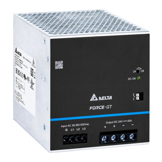
TECHNICAL DATASHEET
Force-GT DIN Rail Power Supply
24 V 960 W 3 Phase / DRF-24V960W3GBA
General Description
The Force-GT Series DIN rail industrial power supply features high power density and high efficiency. The Series offers overcurrent
protection in constant current mode, making it suitable for charging applications. Conformal coating is applied on the PCBAs to protect
against dust and pollutants often found in harsh industrial environments. The Series' electromagnetic radiated and conducted emissions
are compliant with heavy industrial Class B Emission standard and Immunity standard, and complies with environmental protection
standards RoHS Directive.
Model Information
Force-GT DIN Rail Power Supply
Model Number
DRF-24V960W3GBA
Model Numbering
DR
F –
DIN Rail Product Series
F – Force
All parameters are specified at 25°C ambient and AC input 3x unless otherwise indicated.
1
www.DeltaPSU.com (May 2022, Rev. 00)
Input Voltage Range
3 x 320-575 Vac (3-Phase) or
2 x 340-575 Vac (2-Phase)
24V
960W
Output Voltage Output Power Three Phase
Highlights & Features
Universal AC input voltage range
•
•
Built-in constant current circuit for charging applications
Full load operating temperature up to 55°C
•
•
Cold start at -40°C
Ultra-Slim design
•
•
Reduced no-load power consumption
Built-in DC OK relay and LED indicator
•
•
Conformal coating on PCBAs to protect against common dust
and pollutants
Safety Standards
CB Certified for worldwide use
Model Number:
Unit Weight:
Dimensions (H x W x D):
Rated Output Voltage
24 Vdc
3
G
G – General Type
DRF-24V960W3GBA
2.26
kg (4.98 lb)
124 x 110 x 128.7 mm
(4.88 x 4.33 x 5.07 inch)
Rated Output Current
40.0 A
B
A
B – Screw Terminal Delta Standard
Advertisement
Table of Contents

Related Manuals for Delta FORCE-GT DRF-24V960W3GBA


Summary of Contents for Delta FORCE-GT DRF-24V960W3GBA
- Page 1 DIN Rail Product Series Output Voltage Output Power Three Phase G – General Type B – Screw Terminal Delta Standard F – Force All parameters are specified at 25°C ambient and AC input 3x unless otherwise indicated. www.DeltaPSU.com (May 2022, Rev. 00)
-
Page 2: Specifications
TECHNICAL DATASHEET Force-GT DIN Rail Power Supply 24 V 960 W 3 Phase / DRF-24V960W3GBA Specifications Input Ratings / Characteristics Nominal Input Voltage 3 x 380-500 Vac Input Voltage Range 3 x 320-575 Vac (3-Phase) or 2 x 340-575 Vac (2-Phase) Nominal Input Frequency 50-60 Hz Input Frequency Range... - Page 3 TECHNICAL DATASHEET Force-GT DIN Rail Power Supply 24 V 960 W 3 Phase / DRF-24V960W3GBA Mechanical Case Cover / Chassis Aluminum Dimensions (H x W x D) 124 x 110 x 128.7 mm (4.88 x 4.33 x 5.07 inch) Unit Weight 2.26 kg (4.98 lb) Indicator Green LED...
- Page 4 TECHNICAL DATASHEET Force-GT DIN Rail Power Supply 24 V 960 W 3 Phase / DRF-24V960W3GBA Protections Overvoltage < 35 V, Hiccup Mode, Non-Latching (Auto-Recovery) Overload / Overcurrent 110 – 150% of rated load current, Auto-recovery Continuous current limit Mode* (Vo > 80%) Over Temperature 60°C-80°C Surrounding Air Temperature @ 100% load, Non-Latching (Auto-Recovery)
- Page 5 TECHNICAL DATASHEET Force-GT DIN Rail Power Supply 24 V 960 W 3 Phase / DRF-24V960W3GBA Emissions (CE & RE) Generic Standards: EN/BS EN 61000-6-3, CISPR 32, EN/BS EN 55032, FCC Title 47: Class B Component Power Supply for General Use EN/BS EN 61204-3 Immunity Generic Standards: EN/BS EN 55024, EN/BS EN 55035,...
-
Page 6: Block Diagram
TECHNICAL DATASHEET Force-GT DIN Rail Power Supply 24 V 960 W 3 Phase / DRF-24V960W3GBA Block Diagram Device Description Input terminal block connector Output terminal block connector DC OK relay contact DC voltage adjustment potentiometer DC OK LED (Green) QR code for product link Universal mounting rail system All parameters are specified at 25°C ambient and AC input 3x unless otherwise indicated. - Page 7 TECHNICAL DATASHEET Force-GT DIN Rail Power Supply 24 V 960 W 3 Phase / DRF-24V960W3GBA Dimensions H x W x D: 124 x 110 x 128.7 mm (4.88 x 4.33 x 5.07 inch) Item Device Description Input terminal block connector Pin 1: PE Pin 2: L1 Pin 3: L2...
-
Page 8: Engineering Data
TECHNICAL DATASHEET Force-GT DIN Rail Power Supply 24 V 960 W 3 Phase / DRF-24V960W3GBA Engineering Data Note Output Load De-rating VS Surrounding Air Temperature Power supply components may degrade, or be damaged, when the power supply is continuously used outside the shaded region, refer to the graph shown in Fig. -
Page 9: Assembly And Installation
TECHNICAL DATASHEET Force-GT DIN Rail Power Supply 24 V 960 W 3 Phase / DRF-24V960W3GBA Assembly & Installation The power supply unit (PSU) can be mounted on 35 mm DIN rails in accordance with EN 60715. The device should be installed with input terminal block at the bottom. - Page 10 TECHNICAL DATASHEET Force-GT DIN Rail Power Supply 24 V 960 W 3 Phase / DRF-24V960W3GBA Safety Instructions Vertical Mounting Horizontal Mounting • ALWAYS switch mains of input power OFF before connecting and disconnecting the input voltage to the unit. If mains are not turned OFF, there is risk of explosion / severe damage.
- Page 11 TECHNICAL DATASHEET Force-GT DIN Rail Power Supply 24 V 960 W 3 Phase / DRF-24V960W3GBA Functions DC OK Relay Contacts and LED Indicator Characteristics DC OK Relay Contacts Status Characteristics Contact closes The output voltage > 90% of its steady state set value. The output voltage <...
- Page 12 TECHNICAL DATASHEET Force-GT DIN Rail Power Supply 24 V 960 W 3 Phase / DRF-24V960W3GBA Graph illustrating the Start-up Time, Rise Time, and Hold-up Time Start-up Time The time required for the output voltage to reach 90% of its final steady state set value, after the input voltage is applied. Rise Time The time required for the output voltage to change from 10% to 90% of its final steady state set value.
- Page 13 TECHNICAL DATASHEET Force-GT DIN Rail Power Supply 24 V 960 W 3 Phase / DRF-24V960W3GBA Overload & Overcurrent Protections (Auto-Recovery) Overvoltage Protection (Auto-Recovery) The power supply’s Overload (OLP) and Overcurrent (OCP) The power supply’s overvoltage circuit will be activated when its Protections will be activated when output current (I ) is 110~150% internal feedback circuit fails.
-
Page 14: Operating Mode
TECHNICAL DATASHEET Force-GT DIN Rail Power Supply 24 V 960 W 3 Phase / DRF-24V960W3GBA Operating Mode Fig. 4 DC Input Operation Connection Diagram DC Input Operation Step 1. Use a battery or similar DC source. Step 2. Connect either connections of +pole and -pole to L1/L2/L3 as below. •... - Page 15 Attention Delta provides all information in the datasheets on an “AS IS” basis and does not offer any kind of warranty through the information for using the product. In the event of any discrepancy between the information in the catalog and datasheets, the datasheets shall prevail (please refer to www.DeltaPSU.com for the latest datasheets information).