Table of Contents
Advertisement
Quick Links
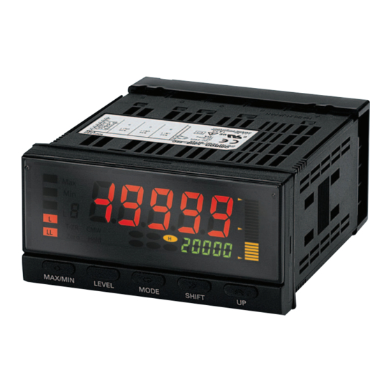
Process Indicator
K3HB-X
A Process Indicator Ideal for Discriminating and
Displaying Measurements for Voltage/Current
Signals
• Easy recognition of judgement results using color display that can be
switched between red and green. *
• Equipped with a position meter for monitoring operating status trends.
• External event input allows use in various measurement and discrimina-
tion applications.
• Series expanded to include DeviceNet models.
• Short body with depth of only 95 mm (from behind the front panel), or 97
mm for DeviceNet models.
• UL certification approval (Certification Mark License).
• CE Marking conformance by third party assessment body.
• Water-resistant enclosure conforms to NEMA 4X (equivalent to IP66).
• Capable of high-speed sampling at 50 times per second (20 ms)
• Easy-to-set two-point scaling allows conversion and display of any user-
set values.
* Visual confirmation of judgement results is not supported on models that do not have
an output or models that do not support DeviceNet.
You can change the display color by setting it, but you cannot switch it based on the
judgement results.
Refer to Safety Precautions for All Digital Panel
Meters.
Model Number Structure
■ Model Number Legend
Base Units and Optional Boards can be ordered individually or as sets.
Base Units
K3HB-X@
1
5
1. Input Sensor Code
VD: DC voltage input
AD: DC current input
VA: AC voltage input
AA: AC current input
5. Supply Voltage
100-240 VAC: 100 to 240 VAC
24 VAC/VDC: 24 VAC/VDC
Optional Board
Sensor Power Supply/Output Boards
K33-@
2
Relay/Transistor Output Boards
K34-@
3
Event Input Boards
K35-@
4
Note: The following combinations are not possible.
• Communications (FLK@A) + DeviceNet (DRT)
• Communications (FLK@A) + BCD output (BCD)
• Linear current/voltage (L@A) + DeviceNet (DRT)
For the most recent information on models that have been certified for
safety standards, refer to your OMRON website.
Base Units with Optional Boards
K3HB-X@-@@@
1 2 3 4
5
2. Sensor Power Supply/Output Type Code
None: None
CPA: Relay output (PASS: SPDT) + Sensor power supply
(12 VDC +/−10%, 80 mA) (See note 1.)
L1A: Linear current output (0 to 20 or 4 to 20 mA DC) + Sensor power supply
(12 VDC +/−10%, 80 mA) (See note 2.)
L2A: Linear voltage output (0 to 5, 1 to 5, or 0 to 10 VDC) + Sensor power supply
(12 VDC +/−10%, 80 mA) (See note 2.)
A: Sensor power supply (12 VDC +/−10%, 80 mA)
FLK1A: Communications (RS-232C) + Sensor power supply
(12 VDC +/−10%, 80 mA) (See note 2.)
FLK3A: Communications (RS-485) + Sensor power supply
(12 VDC +/−10%, 80 mA) (See note 2.)
Note: 1. CPA can be combined with relay outputs only.
2. Only one of the following can be used by each Digital Indicator:
RS-232C/RS-485 communications, a linear output, or
DeviceNet communications.
3. Relay/Transistor Output Type Code
None: None
C1: Relay contact (H/L: SPDT each)
C2: Relay contact (HH/H/LL/L: SPST-NO each)
T1: Transistor (NPN open collector: HH/H/PASS/L/LL)
T2: Transistor (PNP open collector: HH/H/PASS/L/LL)
BCD *: BCD output + transistor output (NPN open collector: HH/H/PASS/L/
LL)
DRT: DeviceNet (See note 2.)
* A Special BCD Output Cable (sold separately) is required.
4. Event input Type Code
None: None
1: 5 inputs (M3 terminal blocks), NPN open collector
2 *: 8 inputs (10-pin MIL connector), NPN open collector
3: 5 inputs (M3 terminal blocks), PNP open collector
4 *: 8 inputs (10-pin MIL connector), PNP open collector
* There is no bank selection for "None" and "DeviceNet" types of "Transistor
Output Type Code".
CSM_K3HB-X_DS_E_12_4
1
Advertisement
Table of Contents

Related Manuals for Omron K3HB-X


Summary of Contents for Omron K3HB-X
- Page 1 For the most recent information on models that have been certified for You can change the display color by setting it, but you cannot switch it based on the safety standards, refer to your OMRON website. judgement results. Refer to Safety Precautions for All Digital Panel Meters.
-
Page 2: Accessories (Sold Separately)
Note: 1. DC power supply models require a control power supply capacity of approximately 1 A per Unit when power is turned ON. Particular attention is required when using two or more DC power supply models. The OMRON S8VS-series DC Power Supply Unit is recommend- 2. - Page 3 K3HB-X ■ Characteristics −19,999 to 99,999 Display range Sampling period 20 ms (50 times/second) Comparative output response time DC input: 100 ms max.; AC input: 300 ms max. (The time until the comparative output is output when there is a forced sudden change in the input signal from 15% to 95% or 95% to 15%.)
- Page 4 K3HB-X ■ Input Range (Measurement Range and Accuracy) CAT II Input type Range Set value Measurement range Maximum Input Accuracy Allowable measurement range impedance instantaneous overload (30 s) a Ud K3HB-XVD ±199.99 V -199.99 to 219.99 V 10 MΩ min.
-
Page 5: Common Specifications
K3HB-X Common Specifications ■ Event Input Ratings Input type S-TMR, HOLD, RESET, ZERO, BANK1, BANK2, TIMING BANK4 Contact ON: 1 kΩ max., OFF: 100 kΩ min. No-contact ON residual voltage: 2 V max. ON residual voltage: 3 V max. OFF leakage current: 0.1 mA max. -
Page 6: Devicenet Communications
K3HB-X DeviceNet Communications Communications protocol Conforms to DeviceNet Supported communi- Remote I/O communications Master-Slave connection (polling, bit-strobe, COS, cyclic) cations Conforms to DeviceNet communications standards. I/O allocations Allocate any I/O data using the Configurator. Allocate any data, such as DeviceNet-specific parameters and variable area for Digital Indicators. - Page 7 K3HB-X ■ Power Supply Derating Curve for Sensor (Reference Value) With 12 V With 10 V Max. current (mA) Max. current (mA) −20 −10 −20 −10 Ambient temperature (°C) Ambient temperature (°C) Note: 1. The above values are for standard mounting. The derating curve differs depending on the mounting conditions.
- Page 8 Refer to the following User's Manual for application precautions and other information required when using the Digital Indicator: K3HB-S/-X/-V/-H Digital Indicator User's Manual (Cat. No. N128) The manual can be downloaded from the following site in PDF format: OMRON Industrial Web http://www.fa.omron.co.jp...
-
Page 9: Terminal Arrangement
K3HB-X ■ Connections Terminal Arrangement Note: Insulation is used between signal input, event input, output, and power supply terminals. A Operating Power Supply 100 to 240 VAC 24 VAC/ VDC *1 Check the required power supply type. *2 There is no polarity on models for 24 VAC/DC. - Page 10 K3HB-X E Analog Input Process Indicator Weighing Indicator Temperature Indicator Linear Sensor Indicator K3HB-X K3HB-V K3HB-H K3HB-S AC voltage only A, B Input B Current input Input A Voltage input Input A Input B D Event Input • Use terminal pin D6 as the common terminal.
- Page 11 K3HB-X ■ Main Functions Measurement Timing Hold Normal Sampling Hold • Continuously performs measurement and always outputs based on • Holds the measurement at the rising edge of the TIMING signal. comparative results. Input Sampling hold value Input H comparative set value...
- Page 12 K3HB-X ■ Input Compensation/Display Display Value Selection Forced-zero The current display value can be selected from the present value, the Forces the present value to 0. (Convenient for setting reference val- maximum value, and the minimum value. ues or deducting tares for weight measurement.)
- Page 13 K3HB-X ■ Output Comparative Output Pattern Hysteresis Prevents comparative output chattering when the measurement The output pattern for comparative outputs can be selected. In addi- value fluctuates slightly near the set value. tion to high/low comparison with set values, output based on level changes is also possible.
- Page 14 K3HB-X ■ Wiring Precautions ■ Mounting Method • For terminal blocks, use the crimp terminals suitable for M3 screws. 1. Insert the K3HB into the mounting cutout in the panel. • Tighten the terminal screws to the recommended tightening torque 2.
-
Page 15: Precautions For Safe Use
Do not use the equipment for measurements within 8. Use the specified size of crimp terminals (M3, width: 5.8 mm Measurement Categories III and IV for K3HB-X and II, III, max.) for wiring. To connect bare wires, use AWG22 (cross sec- and IV for K3HB-S, K3HB-V, and K3HB-H (according to tion: 0.326 mm... - Page 16 K3HB-X ■ Noise Countermeasures 1. Do not install the product near devices generating strong high-fre- quency waves or surges, such as high-frequency welding and sewing machines. 2. Mount a surge suppressor or noise filter to peripheral devices generating noise, in particular, motors, transformers, solenoids, and magnet coils.
- Page 17 (a) Exclusive Warranty. Omron’s exclusive warranty is that the Products will be free from defects in materials and workmanship for a period of twelve months from the date of sale by Omron (or such other period expressed in writing by Omron). Omron disclaims all other warranties, express or implied.