Omron K3HB-C Series Manual
Up/down counting pulse indicator
Hide thumbs
Also See for K3HB-C Series:
- User manual (183 pages) ,
- Datasheet (33 pages) ,
- Manual (33 pages)
Table of Contents
Advertisement
Quick Links
Up/Down Counting Pulse Indicator
K3HB-C
Measure High-speed Up/down Pulses with this
Up/down Pulse Meter.
• Visual conf0rmation of judgement results through display colors that
switch between red and green. *1
• Perfect for Measuring Rotary Encoder and ON/OFF Pulse Signals at High
Speed
Cumulative pulse input is 50 kHz, quadrature pulse inputs are 25 kHz, and up/
down pulse inputs are 30 kHz.
Note: No-voltage contacts of up to 30 Hz are supported.
• The count value can be converted to any value.
The length equivalent for any pulse can be set to any desired value. This is
effective for feed amount and position monitor displays.
• DeviceNet models added to the series. *2
*1 Visual confirmation of judgement results is not supported on models that do not have an
output or models that do not support DeviceNet.
You can change the display color by setting it, but you cannot switch it based on the judgement results.
*2 DeviceNet models have a depth of 97 mm.
Refer to Safety Precautions for All Digital Panel
Meters.
Model Number Structure
■ Model Number Legend
Base Units and Optional Boards can be ordered individually or as sets.
Base Units
K3HB-C @
1
5
1. Input Sensor Code
NB: NPN input/voltage pulse input
5. Supply Voltage
100-240 VAC: 100 to 240 VAC
24 VAC/VDC: 24 VAC/VDC
Optional Board
Sensor Power Supply/Output Boards
K33-@
2
Relay/Transistor Output Boards
K34-@
3
Event Input Boards
K35-@
4
Note: The following combinations are not possible.
• Communications (FLK@A) + DeviceNet (DRT)
• Communications (FLK@A) + BCD output (BCD)
• Linear current/voltage (L@A) + DeviceNet (DRT)
For the most recent information on models that have been certified for
safety standards, refer to your OMRON website.
Base Units with Optional Boards
K3HB-C@-@@@
1
2 3 4
5
2. Sensor Power Supply/Output Type Code
None: None
CPA:
Relay output (PASS: SPDT) + Sensor power supply
(12 VDC±10%, 80 mA) (See note 1.)
L1A:
Linear current output (0 to 20 or 4 to 20 mA DC) + Sensor power supply
(12 VDC±10%, 80 mA) (See note 2.)
L2A:
Linear voltage output (0 to 5, 1 to 5, or 0 to 10 VDC) + Sensor power supply
(12 VDC±10%, 80 mA) (See note 2.)
A:
Sensor power supply (12 VDC ±10%, 80 mA)
FLK1A: Communications (RS-232C) + Sensor power supply
(12 VDC±10%, 80 mA) (See note 2.)
FLK3A: Communications (RS-485) + Sensor power supply
(12 VDC±10%, 80 mA) (See note 2.)
Note: 1. CPA can be combined with relay outputs only.
2. Only one of the following can be used by each Digital Indicator: RS-232C/
RS-485 communications, a linear output, or DeviceNet communications.
3. Relay/Transistor Output Type Code
None: None
C2:
Relay contact (HH/H/LL/L: SPST-NO each)
T1:
Transistor (NPN open collector: HH/H/PASS/L/LL)
T2:
Transistor (PNP open collector: HH/H/PASS/L/LL)
BCD∗:BCD output + transistor output (NPN open collector: HH/H/PASS/L/LL)
DRT: DeviceNet (See note 2.)
∗ A Special BCD Output Cable (sold separately) is required.
4. Event Input Type Code
None: None
1:
5 inputs (M3 terminal block), NPN open collector
2:
8 inputs (10-pin MIL connector), NPN open collector
3:
5 inputs (M3 terminal block), PNP open collector
4:
8 inputs (10-pin MIL connector), PNP open collector
CSM_K3HB-C_DS_E_15_1
1
Advertisement
Table of Contents

Related Manuals for Omron K3HB-C Series


Summary of Contents for Omron K3HB-C Series
- Page 1 *2 DeviceNet models have a depth of 97 mm. For the most recent information on models that have been certified for Refer to Safety Precautions for All Digital Panel safety standards, refer to your OMRON website. Meters. Model Number Structure ■...
-
Page 2: Accessories (Sold Separately)
Note: 1. DC power supply models require a control power supply capacity of approximately 1 A per Unit when power is turned ON. Particular attention is required when using two or more DC power supply models. The OMRON S8VS-series DC Power Supply Unit is recommended. - Page 3 K3HB-C ■ Characteristics −19,999 to 99,999 Display range Measurement range Functions F1, F2: ±2 gigacounts Functions F3: 0 to 4 gigacounts Input signals • Contact input (dry contact input) (30 Hz max. with ON/OFF pulse width of 15 ms min.) •...
-
Page 4: Operation
K3HB-C Operation ■ Functions (Operating Modes) F1 to F3 Function name Function No. Individual inputs Phase differential inputs f2 Pulse counting input Function Operation Operation image (application) Counts input A as incremental pulses and input B as Counting the number of people entering an area Individual decremental pulses. - Page 5 K3HB-C ■ What Is Prescaling? Prescaling converts the count value to any numeric value. To display @@@@.@ mm in a system that outputs 250 pulses for a 0.5-m feed, the length per pulse = 500 mm (0.5 m) ÷ 250 = 2. 1.
-
Page 6: Common Specifications
K3HB-C Common Specifications ■ Event Input Ratings K3HB-P/-C HOLD, RESET, BANK1, BANK2, BANK4 Contact ON: 1 kΩ max., OFF: 100 kΩ min. No-contact ON residual voltage: 2 V max. OFF leakage current: 0.1 mA max. Load current: 4 mA max. Maximum applied voltage: 30 VDC max. -
Page 7: Devicenet Communications
K3HB-C DeviceNet Communications Communications protocol Conforms to DeviceNet Supported Remote I/O Master-Slave connection (polling, bit-strobe, COS, cyclic) communications communications Conforms to DeviceNet communications standards. I/O allocations Allocate any I/O data using the Configurator. Allocate any data, such as DeviceNet-specific parameters and variable area for Digital Indicators. Input area: 2 blocks, 60 words max. -
Page 8: Terminal Arrangements
(HONDA TSUSHIN KOGYO CO., LTD.) 80 mA 80 mA − supply Special Cable (Sold separately) K32-BCD (OMRON) <L2A> <L1A> (HDR-E50MAG1 with 0.3-m cable) Sensor power supply The BCD COMMON is shared. The pins indicated in the above diagram as blank (white) boxes have been removed. - Page 9 9: BANK1 10: COM HOLD COMPENSATION: D5 • Applicable Connector (Sold separately) 4.7 kΩ RESET XG4M-1030 (OMRON) • Special Cable (Sold separately) COMPENSATION 3.9 kΩ K32-DICN (OMRON) (XG4M-1030 with 3-m cable) Note: The actual terminal label abbreviates "COMPENSATION" to "CMP."...
- Page 10 K3HB-C ■ Derating Curve for Sensor Power Supply (Reference Values) For 12V −20 −10 Ambient temperature (°C) Note: 1. The above values were obtained under test conditions with the standard mounting. The derating curve will vary with the mounting conditions, so be sure to adjust accordingly. 2.
-
Page 11: Continuous Data Output
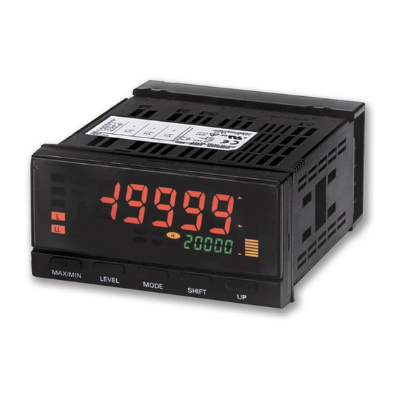
Refer to the following User's Manual for application precautions and other information required when using the Digital Indicator: K3HB-R/P/C Digital Indicator User's Manual (Cat. No. N136) The manual can be downloaded from the following site in PDF format: OMRON Industrial Web http://www.fa.omron.co.jp... - Page 12 K3HB-C ■ Component Names and Functions Max./Min. status indicator PV display Turns ON when the maximum value or minimum Displays PVs, maximum values, value is displayed in the RUN level. minimum values, parameter names, and error names. Level/bank display Position meter In RUN level, displays the bank if the bank function is Displays the position of the PV ON.
-
Page 13: Wiring Precautions
K3HB-C ■ Dimensions 101.2 Terminal cover (included) Panel Cutout Dimensions Character Size for Main Display (mm) PV display SV display 120 min. *2 14.2 (112) 75 min. +0.8 +0.6 95 *1 *2. Leave a distance of at least 140 mm when using the Wate Cover Y92A-49N. -
Page 14: Main Functions
K3HB-C Main Functions ■ Main Functions and Features Measurement Outputs func out-p Function Comparative Output Pattern The K3HB-R has the following six functions for receiving and Zone and level comparative output patterns can be selected for displaying input pulses. comparative outputs. F1: Rotation (rpm)/circumferential speed F2: Absolute ratio off-d... - Page 15 K3HB-C Display Other disp bnk-c Display Value Selection Bank Selection The display value can be set to the present value, the maximum Switch between 8 comparative value banks using the keys on the value, or the minimum value. front panel or external inputs. A set of set comparative values can be selected as a group.
- Page 16 (a) Exclusive Warranty. Omron’s exclusive warranty is that the Products will be free from defects in materials and workmanship for a period of twelve months from the date of sale by Omron (or such other period expressed in writing by Omron). Omron disclaims all other warranties, express or implied.
- Page 17 Mouser Electronics Authorized Distributor Click to View Pricing, Inventory, Delivery & Lifecycle Information: Omron K3HB-CNB 24VAC/VDC K3HB-CNB 100-240VAC...