Omron K3MA-J Manual
Process meter
Hide thumbs
Also See for K3MA-J:
- User manual (112 pages) ,
- Instruction manual (2 pages) ,
- Manual (18 pages)
Table of Contents
Advertisement
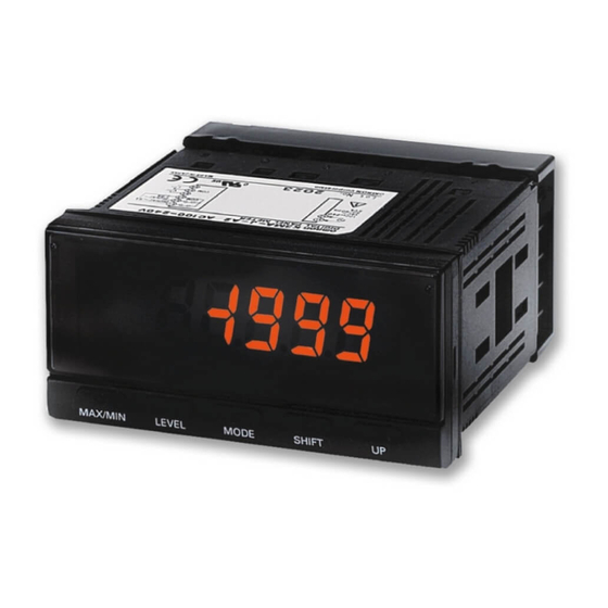
Process Meter
K3MA-J
Highly Visible LCD Display with 2-color (Red
and Green) LEDs
• Multi-range DC voltage/current input.
• Front-panel key operation for easy setting.
• Average processing function suppresses flicker.
• Scaling, front-panel forced-zero, zero-limit functions.
• Easy confirmation of max/min display.
• Short 80-mm depth (measured from edge of face plate).
• Finger protective cover (standard equipment) guards against
electric shock.
• Water- and dust-proof NEMA4X (IP66 equivalent) front panel.
• Recognized to U.S. and Canadian requirements under the
Component Recognition Program of UL.
• CE marking.
Model Number Structure
Model Number Legend
K3MA-J-@
1 2
3
1. Input Type
J:
DC voltage/current
2. Output Type
None: No output
A2:
2 relay contact outputs (SPST-NO)
Ordering Information
List of Models
Input type
DC voltage/current
100 to 240 VAC
24 VAC/VDC
Accessories (Order Separately)
Name
Splash-proof Soft Cover
Hard Cover
Supply voltage
None
2 relay contact outputs (SPST-NO)
None
2 relay contact outputs (SPST-NO)
3. Supply Voltage
100-240VAC: 100 to 240 VAC
24VAC/VDC: 24 VAC/VDC
Output
K3MA-J 100-240VAC
K3MA-J-A2 100-240VAC
K3MA-J 24VAC/VDC
K3MA-J-A2 24VAC/VDC
Shape
K32-49SC
K32-49HC
Process Meter
Model
Model
K3MA-J
1
Advertisement
Table of Contents

Related Manuals for Omron K3MA-J


Summary of Contents for Omron K3MA-J
-
Page 1: Model Number Structure
• Average processing function suppresses flicker. • Scaling, front-panel forced-zero, zero-limit functions. • Easy confirmation of max/min display. • Short 80-mm depth (measured from edge of face plate). • Finger protective cover (standard equipment) guards against electric shock. • Water- and dust-proof NEMA4X (IP66 equivalent) front panel. -
Page 2: Specifications
1 s, or 100 ns for square-wave noise with 1 ns. 1 s, or 100 ns for square-wave noise with 1 ns. Vibration resistance Vibration: 10 to 55 Hz, Acceleration: 50 m/s 5 min each in X, Y, and Z directions for 10 sweeps. Shock resistance 150 m/s (100 m/s for relay contact outputs) 3 times each on 3 axes, 6 directions. -
Page 3: Measuring Ranges
Characteristics Input signal DC voltage/current (0 to 20 mA, 4 to 20 mA, 0 to 5 V, 1 to 5 V, 5 V, 10 V) A/D conversion Double integral method Sampling period 250 ms Display refresh period Sampling period (sampling times multiplied by number of measurements for averaging if average pro- cessing is selected.) -
Page 4: Terminal Arrangement
Current input For voltage input For current input Terminal No. Name Description Operation power Connects the operation power supply. Analog input Connects the voltage or current analog input. Outputs Outputs the relay outputs. Block Diagram Input Input circuit Micro- Display computer... -
Page 5: Operation
Any input value DISPLAY1: Displayed value corresponding to INPUT1 When DISPLAY1 is set for INPUT1, and DISPLAY2 is set for INPUT2, a line will be displayed joining the two points. (Raise shift, reverse scaling, plus/minus display, etc., can be adjusted as desired.) -
Page 6: Convenient Functions
Convenient Functions Scaling Teach The parameters (inp.1, inp.2) for the K3MA-J’s initial setting level can be set using actual input values with the teaching function. After displaying the parameters, the actual input settings can be made with the following operation. -
Page 7: Parameter Initialization
Forced-zero Function Models Only) It is possible to shift from a value to the zero point with one touch of the Up Key on the front panel (for example, when adjusting reference The hysteresis of comparative outputs can be set to prevent chatter- values). - Page 8 Used to allow the main indicator to indicate parameters sequentially. 7. Shift Key Used to enable a set value to be changed. When changing a set value, this key is used to move along the digits. 8. Up Key Used to change a set value. Used to set or clear a forced-zero function when a measurement value is being displayed.
-
Page 9: Application Examples
• Use the following M3 crimp terminals. 5.8 mm max. 3. Fit the adaptor into the grooves on the left and right sides of the rear case, then push it until it contacts the panel to secure the 5.8 mm max. -
Page 10: General Precautions
Do not 3. Check each terminal for correct number and polarity before con- route the wiring for the product in parallel with or tie it in a bundle necting it. Incorrect or reverse connections may damage or burn with power lines. -
Page 11: Operating Procedures
Levels “Level” refers to a grouping of parameters. The following table lists the operations that are possible in each of the levels, and the diagram tells how to move between levels. There are some parameters that are not displayed for certain models. - Page 12 Parameters Note: 1. Some parameters are not displayed for certain models. 2. The K3MA-J will stop measurement if the level is changed to the initial setting level or the advanced-function setting level. 3. If the input range is changed, some parameters are set to default values. Therefore, set the input range first.
- Page 13 Press Level more than 3 s. Press Level Key for more than 1 s. Advanced-function Initial setting level setting level Press Level Enter more than 1 s. password " 0169" Parameter Input type initialization MODE MODE Scaling Average input value 1...
-
Page 14: Initial Settings
Allowed level. Allowed Prohibited • Initial setting is 0. • This cannot be displayed on models not equipped with the compar- Select the input type. ative output function. Set the scaling values and specify output operating action as required. Setting Level Lockout Restricts shifting to initial setting level or advanced-function setting level. -
Page 15: Setting Example
Troubleshooting When an error occurs, error details will be displayed on the main indicator. Confirm the error from the main indicator and take the appropriate coun- termeasures. Level... -
Page 16: Warranty And Limitations Of Liability
Warranty and Limitations of Liability WARRANTY OMRON’s exclusive warranty is that the products are free from defects in materials and workmanship for a period of one year (or other period if specified) from date of sale by OMRON. OMRON MAKES NO WARRANTY OR REPRESENTATION, EXPRESS OR IMPLIED, REGARDING NON-INFRINGEMENT, MERCHANTABILITY, OR FITNESS FOR PARTICULAR PURPOSE OF THE PRODUCTS.