Omron K3HB Manual
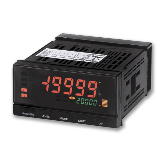
Digital indicators k3hb series
Hide thumbs
Also See for K3HB:
- Manual (147 pages) ,
- Datasheet (33 pages) ,
- Technical communications user's manual (147 pages)

Related Manuals for Omron K3HB


Summary of Contents for Omron K3HB
- Page 1 Digital Indicators K3HB Series Distinct by Design, Distinguished in Performance K3HB-H K3HB-S K3HB-X K3HB-V...
- Page 2 Output L Bottom hold value Time Output LL TIMING Note: The HH, H, L, or LL outputs must be set in that order for the input zone outputs to output correctly. Peak-to-peak value Input (This is because the comparative set values and outputs for (b2−a2)
- Page 3 Note: The applications provided in this catalog are intended as reference only. Do not attempt to use any of them in real systems without first con- firming machine and device functions and safety. For applications that require safety, ensure that there is sufficient leeway in ratings and performances, install fail-safe measures, and take any other safety measures required by the application.
-
Page 4: Process Indicator
VA: AC voltage input (12 VDC +/−10%, 80 mA) (See note 2.) AA: AC current input L2A: Linear voltage output (DC0(1) − 5 V, 0 to 10 V) + Sensor power supply 5. Supply Voltage (12 VDC +/−10%, 80 mA) (See note 2.) A: Sensor power supply (12 VDC +/−10%, 80 mA) -
Page 5: Specifications
DeviceNet connector (Hirose HR31-5.08P-5SC(01)) and crimp terminals (Hirose HR31-SC-121) (See note Note: 1. DC power supply models require a control power supply capacity of approximately 1 A per Unit when power is turned ON. Particular attention is required when using two or more DC power supply models. The OMRON S8VS-series DC Power Supply Unit is recommend- 2. - Page 6 Display range Sampling period 20 ms (50 times/second) Comparative output response time DC input: 100 ms max.; AC input: 300 ms max. Linear output response time DC input: 150 ms max.; AC input: 420 ms max. 20 M Ω min. (at 500 VDC)
- Page 7 Note: 1. The accuracy is for an input frequency range of 40 Hz to 1 kHz (except for AD current input A and B ranges) and an ambient temperature of 23 ±5 ° C. The error, however, increases below 10% of the maximum input value.
- Page 8 (10 VDC +/ − 5%, 100 mA) (See note 2.) 100-240 VAC: 100 to 240 VAC L2B: Linear voltage output (DC0(1) − 5 V, 0 to 10 V) + Sensor power supply 24 VAC/VDC: 24 VAC/VDC (10 VDC +/ − 5%, 100 mA) (See note 2.) B: Sensor power supply (10 VDC +/ −...
- Page 9 DeviceNet connector (Hirose HR31-5.08P-5SC(01)) and crimp terminals (Hirose HR31-SC-121) (See note Note: 1. DC power supply models require a control power supply capacity of approximately 1 A per Unit when power is turned ON. Particular attention is required when using two or more DC power supply models. The OMRON S8VS-series DC Power Supply Unit is recommend- 2.
- Page 10 EN61000-4-2: 4 kV (contact), 8 kV (in air) Radiated Electromagnetic Field Immunity EN61000-4-3: 10 V/m 1 kHz sine wave amplitude modulation (80 MHz to 1 GHz) Electrical Fast Transient/Burst Immunity EN61000-4-4: 2 kV (power line), 1 kV (I/O signal line)
- Page 11 Ud ±199.99 mV ±0.1%rdg ± 1 digit max. Note: 1. The accuracy is for an ambient temperature of 23±5 ° C. For all ranges,10% or less of max. input ±0.1% FS. 2. The letters “rdg” mean “reading.” a lc...
-
Page 12: Temperature Indicator
• External event input allows use in various measurement and discrimina- tion applications. • Series expanded to include DeviceNet models. • Short body with depth of only 95 mm (from behind the front panel), or 97 mm for DeviceNet models. • UL certification approval (Certification Mark License). - Page 13 DeviceNet connector (Hirose HR31-5.08P-5SC(01)) and crimp terminals (Hirose HR31-SC-121) (See note Note: 1. DC power supply models require a control power supply capacity of approximately 1 A per Unit when power is turned ON. Particular attention is required when using two or more DC power supply models. The OMRON S8VS-series DC Power Supply Unit is recommended.
- Page 14 − 19,999 to 99,999 Display range Thermocouple input: (±0.3% PV or ±1 ° C, whichever is larger) ± 1 digit max. (See note.) Accuracy Platinum resistance thermometer input: (±0.2% PV or ±0.8 ° C, whichever is larger) ± 1 digit max.
- Page 15 0.1 ° C 0.01 ° C 0.1 ° C Minimum setting unit (comparative set value) The range shown in dark shading indicates the factory setting. Celsius/Fahrenheit Correlation Values and Setting/Specified Ranges Input type Setting range Indication range ° C ° F °...
- Page 16 100-240 VAC: 100 to 240 VAC (12 VDC +/ − 10%, 80 mA) (See note 2.) L2A: Linear voltage output (DC0(1) − 5 V, 0 to 10 V) + Sensor power supply 24 VAC/VDC: 24 VAC/VDC (12 VDC +/ − 10%, 80 mA) (See note 2.) A: Sensor power supply (12 VDC +/ −...
- Page 17 (Hirose HR31-5.08P-5SC(01)) and crimp terminals (Hirose HR31-SC-121) (See note 3.) Note: 1. DC power supply models require a control power supply capacity of approximately 1 A per Unit when power is turned ON. Particular attention is required when using two or more DC power supply models. The OMRON S8VS-series DC Power Supply Unit is recommend- 2.
- Page 18 EN61000-4-2: 4 kV (contact), 8 kV (in air) Radiated Electromagnetic Field Immunity EN61000-4-3: 10 V/m 1 kHz sine wave amplitude modulation (80 MHz to 1 GHz) Electrical Fast Transient/Burst Immunity EN61000-4-4: 2 kV (power line), 1 kV (I/O signal line)
-
Page 19: Sampling And Comparative Output Response Times
The range shown in dark shading indicates the factory setting. Sampling and Comparative Output Response Times The K3HB-S sampling and comparative output response times depend on the calculation methods, timing hold type, and, for simple averaging, the averaging times. Refer to the following description for details. -
Page 20: Common Specifications
■ Event Input Ratings Input type S-TMR, HOLD, RESET, ZERO, BANK1, BANK2, TIMING BANK4 ON: 1 k Ω max., OFF: 100 k Ω min. Contact No-contact ON residual voltage: 2 V max. ON residual voltage: 3 V max. OFF leakage current: 0.1 mA max. -
Page 21: Devicenet Communications
Indicators. Input area: 2 blocks, 60 words max. Output area: 1 block, 29 words max. (The first word in the area is always allocated for the Output Execution Enabled Flags.) Message communications Explicit message communications CompoWay/F communications commands can be executed (using explicit message... -
Page 22: Component Names And Functions
Note: 1. The above values are for standard mounting. The derating curve differs depending on the mounting conditions. 2. Do not use the Sensor outside of the derating area (i.e., do not use it in the area labeled A in the above graphics). Doing so may occa- sionally cause deterioration or damage to internal components. -
Page 23: Continuous Data Output
Digital Indicator narrow pitch connector (manufactured by Honda Tsushin Kogyo Co., Ltd.). Refer to the following User's Manual for application precautions and other information required when using the Digital Indicator: K3HB-S/-X/-V/-H Digital Indicator User's Manual (Cat. No. N128) The manual can be downloaded from the following site in PDF format: OMRON Industrial Web http://www.fa.omron.co.jp... -
Page 24: Terminal Arrangement
Sensor power supply The pins indicated in the above diagram as blank (white) boxes have been removed. * Only one of the following can be used for each Digital Indicator: communications, BCD, or DeviceNet. Contact output Transistor Output (NPN Open Collector) −... - Page 25 (manufactured by DDK) COMMON Stand: 17L-002A (manufactured by DDK) Note: The BCD Output Cable has a D-sub plug. Cover: 17JE-37H-1A (manufactured by DDK); Connector: equivalent to 17JE-23370-02 (D1) (manufactured by DDK) Special Cable (for Event Inputs with 8-pin Connector) Model Appearance...
-
Page 26: Main Functions
Input Calculation • Two input circuits are provided. The input ranges for these circuits can be set independently. For example, one can be set to 4 to 20 mA and the other can be set to 1 to 5 V. - Page 27 0, 2, 4, 6, or 8 and if the setting is 5, releasing the tare zero and forced-zero, measure the combined total.
- Page 28 X V H S Prevents comparative output chattering when the measurement The output pattern for comparative outputs can be selected. In addi- value fluctuates slightly near the set value. tion to high/low comparison with set values, output based on level changes is also possible.
-
Page 29: Wiring Precautions
• Use the crimp terminals suitable for M3 screws shown below. 5.8 mm max. 5.8 mm max. 3. Insert the adapter into the grooves on the left and right sides of the rear case and push until it reaches the panel and is fixed in place. -
Page 30: Precautions For Safe Use
Do not wire in parallel with or in the same cable as power Perform correct setting of the product according to the lines. Other measures for reducing noise include running lines application. - Page 31 Indicator 2 conductors with shield 4. If a noise filter is used for the power supply, check the voltage and current, and install the noise filter as close to the product as pos- sible. 5. Reception interference may occur if the product is used close to a radio, television, or wireless.
-
Page 32: Warranty And Limitations Of Liability
Warranty and Limitations of Liability ■ WARRANTY OMRON's exclusive warranty is that the products are free from defects in materials and workmanship for a period of one year (or other period if specified) from date of sale by OMRON. OMRON MAKES NO WARRANTY OR REPRESENTATION, EXPRESS OR IMPLIED, REGARDING NON-INFRINGEMENT, MERCHANTABILITY, OR FITNESS FOR PARTICULAR PURPOSE OF THE PRODUCTS.