Table of Contents
Advertisement
Quick Links
See also:
Operating Manual
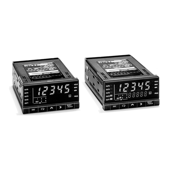
Up/Down Counting Meter
K3NC
An Ideal Interface for High-speed Up/Down
Counting and Serial Communications
• 50-kHz input range for high-speed signal processing.
• A wide selection of outputs: relay, transistor, BCD, linear, or
communications.
• Prescale function available, which displays in units of actual
physical parameters (length, volume, etc.).
• Built-in sensor power supply (12 VDC, 80 mA).
• Banks with four set values and four prescale values.
• Five-stage comparative outputs available.
• Compact 1/8 DIN size.
• Conforms to EMC standards, EN61010-1 (IEC1010-1).
• UL/CSA approved.
Model Number Structure
■ Model Number Legend
Base Units and Output Boards can be ordered individually or as sets. Refer to the Output Board Combinations table on page 130.
Base Units
K3NC -
1
2
3
4
1, 2. Input Sensors Codes
NB:
NPN inputs/Voltage pulse inputs
PB:
PNP inputs
3. Supply Voltage
1:
100 to 240 VAC
2:
12 to 24 VDC
4. Display
A:
Basic
C:
Set Value LED Display
5, 6, 7, 8. Output Type Codes
C2:
5 comparative relay contact outputs (OUT1, 2, 4, 5: SPST-
NO; OUT3: SPDT)
C5:
5 comparative relay contact outputs (OUT1, 2, 4, 5: SPST-
NC; OUT3: SPDT)
T1:
5 comparative transistor outputs (NPN open collector)
T2:
5 comparative transistor outputs (PNP open collector)
B2:
BCD output (NPN open collector) (see note)
B4:
BCD output + 5 transistor outputs (NPN open collector)
L1:
Linear output (4 to 20 mA) (see note)
Note: These output types are available on Basic Models only.
Output Boards
K31 -
5
6
7
8
L2:
L3:
L4:
L5:
L6:
L7:
L8:
L9:
L10: Linear output, 0 to 10 VDC + 5 transistor outputs (NPN open
FLK1: Communication RS-232C (see note)
FLK2: Communication RS-485 (see note)
FLK3: Communication RS-422 (see note)
FLK4: RS-232C + 5 transistor outputs (NPN open collector)
FLK5: RS-485 + 5 transistor outputs (NPN open collector)
FLK6: RS-422 + 5 transistor outputs (NPN open collector)
Base Units with Output Boards
K3NC -
1
2
3
4
Linear output (1 to 5 VDC) (see note)
Linear output (1 mV/10 digits) (see note)
Linear output, 4 to 20 mA + 5 transistor outputs (NPN open
collector)
Linear output, 1 to 5 V + 5 transistor outputs (NPN open col-
lector)
Linear output, 1 mV/10 digits+ 5 transistor outputs (NPN
open collector)
Linear output, 0 to 5 VDC (see note)
Linear output, 0 to 10 VDC (see note)
Linear output, 0 to 5 VDC + 5 transistor outputs (NPN open
collector)
collector)
Up/Down Counting Meter
®
-
5
6
7
8
K3NC
C-129
Advertisement
Table of Contents

Related Manuals for Omron K3NC


Summary of Contents for Omron K3NC
-
Page 1: Model Number Structure
• UL/CSA approved. Model Number Structure ■ Model Number Legend Base Units and Output Boards can be ordered individually or as sets. Refer to the Output Board Combinations table on page 130. Output Boards Base Units Base Units with Output Boards... -
Page 2: Ordering Information
Combination output and BCD output + 5 transistor outputs (NPN open collector) K31-B4 communication boards 4 to 20 mA + 5 transistor outputs (NPN open collector) K31-L4 1 to 5 V + 5 transistor outputs (NPN open collector) K31-L5 1 mV/10 digits + 5 transistor outputs (NPN open collector) -
Page 3: Specifications
Approx. 400 g Note: A K3NC with DC supply voltage requires approximately 1 A DC as control power supply current the moment the K3NC is turned ON. Do not forget to take this into consideration when using several K3NC units. When the K3NC is not in measuring operation (e.g., the K3NC has been just turned ON or is operating for startup compensation time), the display will read “00000”... -
Page 4: Transistor Output
No-voltage contact (30 Hz max., ON/OFF pulse width: 15 ms min.) Voltage pulse (50 kHz max., ON/OFF pulse width: 9 s min., ON voltage: 4.5 to 30 V/OFF voltage: 30 to 2 V) Open collector (50 kHz max., ON/OFF pulse width: 9 s min.) Connectable Sensors ON residual voltage: 3 V max. -
Page 5: Bcd Output
0.5% FS 1.5% FS Permissible load resistance max. min. 1 K min. Note: For the 1 mV/10-digit output, the output voltage changes for every 40 to 50 increment in the display value. ■ Communications Specifications Item RS-232C, RS-422 RS-485 Transmission method... -
Page 6: Input Unit
Connections ■ Terminal Arrangement Terminal Numbers Output unit Output 18 19 20 21 22 23 24 25 26 unit 10 11 12 13 14 15 16 17 Input unit Note: Terminals 7 to 13 are connected internally. Input unit Terminals 7 and 11 are mutually isolated. -
Page 7: Output Unit
9 10 11 12 13 14 15 16 17 18 19 -L5, -L6, -L9, -L10.) 1 2 4 8 1 2 4 8 1 2 4 8 1 2 4 8 1 2 L1, L4: 4 to 20 mA COMMON... -
Page 8: Block Diagram
Note: External reset minimum signal width: 16 ms COMPENSATION Resets the present counting value to the compensation value at the rising edge of a compensation input. In the compensation value setting parameter, it is possible to set to “Effective during incrementing and decrementing a count”... -
Page 9: Operation
16 ms Approx. 30 ms Approximately 30 ms after the REQ signal rises, a sample is taken and the DATA VALID signal is output. Read the data when the DATA VALID signal is ON. The DATA VALID signal will turn OFF in 40 ms, and then in 16 ms, the data will go OFF. - Page 10 Example of Connection to Programmable Controller K3NC PC (SYSMAC) DC Input Unit 1. COMMON 2. 1 3. 2 4. 4 5. 8 23. DATA VALID 24. RUN 25. COMMON Transistor Output Unit 26. REQUEST +5 V 30. RESET 31. POLARITY...
- Page 11 Example of Connection to Display Unit K3NC 1.COMMON 23.DATA VALID 24.RUN 25.COMMON Connected 26.REQUEST 30.RESET 31.POLARITY (Polarity: +, ) M7E-01D@N2 or M7E-01H@N2 M7E Digital Display Unit K3NC C-139 Up/Down Counting Meter...
- Page 12 ■ Output Delay (Reference Value) The following table shows the time required for a K3NC in a system to go into reverse output operation after the counting value reaches the value preset with the K3NC, and is due to the output processing time of the K3NC, signal transmission time of the system, and the relay connected to the K3NC.
- Page 13 The counting value is reset by pressing this key. Teaching is available when the teaching function is enabled. 10. Up Key and Shift Key The digit being set is scrolled by pressing the Shift Key. The set value increases by one whenever the Up Key is pressed. K3NC...
-
Page 14: Engineering Data
Engineering Data Derating Curve for Sensor Power Supply Note: The derating curve shown is for standard installation. The derating curve depends on the mounting direction. Ambient temperature ( C) K3NC C-142 Up/Down Counting Meter... - Page 15 Dimensions Note: All units are in millimeters unless otherwise indicated. Panel Cutouts PV Display +0.8 14.2 +0.8 RESET OUT5 OUT4 OUT3 OUT2 OUT1 Note: The K3NC uses M3.5 terminals. A terminal cover is provided. K3NC C-143 Up/Down Counting Meter...
-
Page 16: Operating Environment
Precautions ■ Correct Use !WARNING Do not touch any of the terminals while the power is being sup- plied. Doing so may result in electric shock. Long-term Use !Caution Use all products within the specified ranges. When using inside a... -
Page 17: Noise Countermeasures
In order to prevent inductive noise, wire the lines connected to the terminal block separately from power lines carrying high voltages or large currents. Also, do not wire in parallel to, or in the same cable as power lines. There are other methods that are effective for reducing noise, such as running wires along ducts and using shield lines. -
Page 18: Operating Procedures
During measurement display, press the Mode Key repeatedly to display the comparative set values in the order OUT1, OUT2, OUT3, OUT4, and OUT5. (With models that have an SV display, the comparative set values are displayed in the SV display.) Comparative set... - Page 19 ■ Setting Procedures The K3NC has four modes: RUN mode for normal operations, Setting mode for initial parameter input, Protect mode for lock-out configuration, and Maintenance mode for initializing set values. The parameters that are accessible on any individual K3NC will vary depending on the Output Board installed.
-
Page 20: Initial Settings
0.5 m. To enable the K3NC to display @@@@.@ (mm), obtain the advanced length of the object per pulse from the following formula. 500 mm (0.5 m)/250 = 2 1. The prescale value is set by the mantissa X multiplied by the exponent Y as follows: 250 pulses Prescale value = 2.0000 x 10... - Page 21 ) are not displayed (and hence cannot be set). Output mode · If the input mode is changed, all parameters will be reset to No key operation for 5 s their initial values. Set the input mode first. Upper limit (H) Note 1: A number in the range 1 to 4 will be displayed.
- Page 22 /1/2 ting and move to the Set value menu next parameter. Scaling menu Setup menu Option menu Note: If there is no key operation for 5 seconds, the setting is automatically registered. K3NC C-150 Up/Down Counting Meter...
-
Page 23: Troubleshooting
■ Troubleshooting When an error occurs, error details will be displayed in the PV display. Take the appropriate countermeasures according to the error displayed. Error display Error contents Comparative output Countermeasure Output BCD output Communications Linear status output output m1.err (M1.ERR) - Page 24 ALL DIMENSIONS SHOWN ARE IN MILLIMETERS. To convert millimeters into inches, multiply by 0.03937. To convert grams into ounces, multiply by 0.03527. In the interest of product improvement, specifications are subject to change without notice. Cat. No. N089-E1-02 K3NC C-152...