
Related Manuals for Broan ERLE1 Series


Summary of Contents for Broan ERLE1 Series
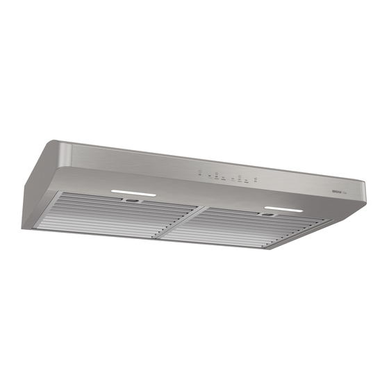
- Page 1 WWW.BROAN.CA WWW.NUTONE.CA RANGE HOOD Series: ERLE1 and NRLE1 INSTALLATION, USE AND CARE MANUAL Serial number: 99045663-004G...
-
Page 2: Table Of Contents
Safety ....... . . 3-4 Operation ......5-6 Cleaning and Maintenance . -
Page 3: Safety
READ AND SAVE THESE INSTRUCTIONS Intended for domestic cooking only INSTALLER: LEAVE THIS MANUAL WITH HOMEOWNER. Register your Broan range hood online at www.broan.ca or register your NuTone range hood online at www.nutone.ca WARNING TO REDUCE THE RISK OF FIRE, ELECTRIC SHOCK, OR INJURY TO PERSONS, OBSERVE THE FOLLOWING: •... - Page 4 WARNING TO REDUCE THE RISK OF A RANGE TOP GREASE FIRE: a) Never leave surface units unattended at high settings. Boilovers cause smoking and greasy spillovers that may ignite. Heat oils slowly on low or medium settings. b) Always turn hood ON when cooking at high heat or when flambeing food (i.e.: Crêpes Suzette, Cherries Jubilee, Peppercorn Beef Flambé).
-
Page 5: Operation
Operation Always turn your hood on before you begin cooking to establish an air flow in the kitchen. Let the blower run for a few minutes to clear the air after you turn off the range. This will help keep the whole kitchen cleaner and fresher. This hood is equipped with infrared sensing controls. - Page 6 LIGHTING/LIGHT INTENSITY CHANGE To turn the lighting ON, touch the sensor corresponding to the desired lighting intensity and the sensor will illuminate. When the lighting is ON, touch the sensor corresponding to the active light intensity to turn the lighting OFF and memorize the intensity. The LED modules included with this hood are the latest in LED cooktop illumination technology specially designed to operate in the elevated temperatures of cooking - offering bright lighting and lasting up to 25 times as long as a standard bulb and greater reliability than typical replacement...
-
Page 7: Cleaning And Maintenance
Cleaning and Maintenance Proper maintenance of the Range Hood will assure proper performance of the unit. MOTORS The motors are permanently lubricated and never need oiling. If the motor bearings make excessive or unusual noise, replace the motor with the exact service motor. The fan wheel should also be replaced. -
Page 8: Installation
For ADA compliance installation guidelines, please type the model number into our website. Recommended Tools and Accessories for Installation • Measuring tape • Phillips screwdriver no. 2 • Nutdriver or socket 11/32” • Flat blade screwdriver (to open knockout holes) •... -
Page 9: Contents
Contents Before proceeding to the installation, check the contents of the box. If items are missing or damaged, contact the manufacturer. Make sure that the following items are included: (1) 3¼” 10” (1) 3¼” 14” (2) G REASE ILTERS AMPER SSEMBLY AMPER SSEMBLY... -
Page 10: Prepare The Hood
Prepare the Hood 1 ] If present, remove all protective polyfilm from the hood and/or parts. 2 ] Remove 2 screws from top of hood. Remove the 3¼’’ x 10’’ adapter and the 3¼’’ x 14’’ adapter frame from the back of hood (see illustration below). Keep the screws for further use. SCREWS SCREWS ... - Page 11 5 ] Remove the parts bag, taped on the inner back of hood, near the left corner. Remove the EZ1 brackets from inside the hood by cutting off the tie wrap. Discard the tie wrap. PARTS BAG LOCATION BRACKETS 6 ] Remove Electrical Power Cable Knockout from top (vertical wiring) or back (horizontal wiring) of hood.
- Page 12 NON-DUCTED INSTALLATION ONLY 7 ] Remove 3 screws retaining the recirculation cover plate to the hood. Discard this plate with its screws. Peel off and discard the membrane covering the recirculation grille, ensuring the openings are totally cleared. SCREWS RECIRCULATION COVER PLATE 3¼”...
- Page 13 3¼” x 10” OR 7” ROUND DUCTED INSTALLATION ONLY 8 ] Remove 3¼” x 10” vertical or 3¼” x 10” horizontal (both are the rectangular central knockout plates, see hatched areas) or 7-inch round knockout plate as appropriate for your ducting method (see F 1 A and 1 B).
-
Page 14: Prepare The Hood Location
Prepare the Hood Location NOTE: Before starting installation, read all the steps of these instructions. Use the illustration below to identify your kitchen cabinet type. FRAMED CABINET FRAMELESS CABINET This manual covers 2 kinds of installation: the standard (without EZ1 brackets) and the EZ1 one-person installation system (using included template and brackets). - Page 15 4 ] Drill a 1/8” dia. pilot hole for house wiring, at B location on template. 5 ] Use a sharp pencil or 1/8” drill bit to mark the locations for the appropriate duct access holes (16 locations for 7” round duct, or 4 corner locations for rectangular duct). Remove the template.
- Page 16 FRAMELESS CABINET Refer to the marking on brackets to determine the correct installation side and orientation. 7/64” Align the corresponding bracket to the cabinet side, while placing rear end of bracket against the wall. Draw a line on the outer edge of the bracket (as shown). ...
-
Page 17: Install The Hood (Ez1 Bracket)
Install the Hood (EZ1 Bracket) OTE: The following procedure applies to both frame or frameless cabinet installations. 1 ] Run house power cable between service panel and hood location. 2 ] There are 2 pairs of recessed holes on each side of the top of the hood (on rear: A and B, on front C and D on illustration below);... - Page 18 7 ] For framed cabinet, secure the hood to the EZ1 brackets using four (4) no. 8-18 x 1/2” metal screws (included in parts bag). Insert two (2) screws per side, in the slots (as shown in insets on illustration below). 8 ] For frameless cabinet, secure the hood to the cabinet using four (4) no.
-
Page 19: Standard Installation
Standard Installation (without EZ1 brackets) 1 ] Use the proper diagram below for placement of ductwork and electrical cutout in cabinet or wall. For a non-ducted installation, DO NOT cut a duct access hole, only cut the hole for electrical wiring. 3¼"... -
Page 20: Install The Hood (Standard Installation)
Install the Hood (Standard Installation) OTE: Two installers are recommended because of the weight of this hood. 1 ] Run house power cable between service panel and hood location. For hood with power cable access located on back of hood, run the house power cable into the hood through the strain relief previously installed in step 6 on page 11. -
Page 21: Connect The Wiring
Connect the Wiring WARNING Risk of electric shock. Electrical wiring must be done by qualifi ed personnel in accordance with all applicable codes and standards. Before connecting wires, switch power off at service panel and lock service disconnecting means to prevent power from being switched on accidentally. -
Page 22: Wiring Diagram
ERLE1 NRLE1 SERIES ( SECOND GENERATION... -
Page 23: Service Parts
ERLE1 NRLE1 First Generation: Serial number SERIES 121810002693 and previous. UANTITY 30" 30" 30" 36" ART NO ESCRIPTION 36" 36" LACK TAINLESS HITE LACK TAINLESS TAINLESS HITE TAINLESS S97020030 ECIRCULATION COVER PLATE HITE INCLUDING SCREWS ECIRCULATION COVER PLATE TAINLESS STEEL INCLUDING S97020031 SCREWS... - Page 24 ERLE1 NRLE1 SERIES Second Generation: Serial number 121810002694 and up. UANTITY 30" 30" 30" 36" ART NO ESCRIPTION 36" 36" LACK TAINLESS HITE LACK TAINLESS TAINLESS HITE TAINLESS S97020030 ECIRCULATION COVER PLATE HITE INCLUDING SCREWS S97020031 ECIRCULATION COVER PLATE TAINLESS STEEL INCL SCREWS S98011873...
-
Page 25: Warranty
Company’s most current written limited warranty for your particular product will control. The most current limited written warranties for the Company’s products can be found at www.broan.ca or www.nutone.ca. Venmar Ventilation ULC, 550 Lemire Blvd., Drummondville, Québec, Canada J2T 7W9 www.broan.ca...