Advertisement
Quick Links
RETAIN THESE INSTRUCTIONS
FOR FUTURE REFERENCE
WARNING
Improper
installation,
service or maintenance can cause personal injury,
loss of life, or damage to property.
Installation and service must be performed by a
licensed professional installer (or equivalent) or a
service agency.
CAUTION
Physical contact with metal edges and corners
while applying excessive force or rapid motion can
result in personal injury. Be aware of, and use
caution when working near these areas during
installation or while servicing this equipment.
IMPORTANT
The Clean Air Act of 1990 bans the intentional
venting of refrigerant (CFCs, HCFCs and HFCs) as
of July 1, 1992. Approved methods of recovery,
recycling or reclaiming must be followed. Fines
and/or
incarceration
noncompliance.
IMPORTANT INFORMATION TO INSTALLER
AIR HANDLER MOTOR
SHIPPING BOLT
A
HORIZONTAL DRAIN PAN (SEE UPFLOW
APPLICATIONS ON PAGE 4 AND
DOWNFLOW APPLICATIONS ON PAGE 6)
D
11/16
adjustment,
alteration,
may
be
levied
for
CHECK FOR AND REMOVE THE FOLLOWING ITEMS BEFORE OPERATING UNIT.
AIR HANDLER MOTOR SHIPPING
BRACKET
C
INSTALLATION
INSTRUCTIONS
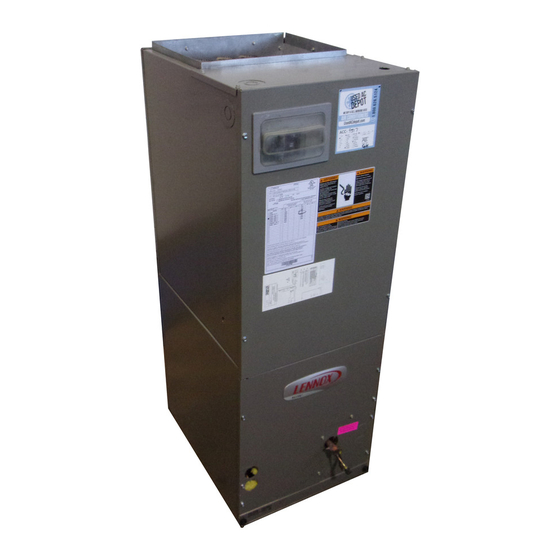
ACBX32CM Units
AIR HANDLER
506316−01
11/16
Table of Contents
ACBX32CM Upflow/Downflow Unit Dimensions
ACBX32CM Horizontal LH/RH Unit Dimensions
G
e
n
e
a r
I l
f n
r o
m
t a
S
h
p i
p
n i
g
a
n
d
P
a
R
e
q
i u
e r
m
e
n
s t
. . . . . . . . . . . . . . . . . . . . . . . . . . . . . . . . .
n I
t s
l a
n i l
g
h t
e
U
n
B
a r
z
n i
g
C
o
n
n
e
t c
n I
t s
l a
n i l
g
h t
e
C
o
n I
s
p
e
t c
n i
g
a
n
d
R
M
a
k
n i
g
E
e l
c
r t
c i
l a
S
e
a
n i l
g
h t
e
U
n
t i
Adjusting the Air Handler Speed
Repairing or Replacing Cabinet Insulation
AIR HANDLER HOUSING SUPPORT PAD
B
REFRIGERANT LINE PLUGS [SEE
BRAZING CONNECTIONS ON PAGE 7]
E
Page 1
o i
n
. . . . . . . . . . . . . . . . . . . . . . . . . . .
k c
n i
g
L
t s i
. . . . . . . . . . . . . . . . . . . . . .
t i
. . . . . . . . . . . . . . . . . . . . . . . . . . . . . .
o i
n
s
. . . . . . . . . . . . . . . . . . . . . . . . . . .
n
d
e
n
s
a
e t
D
a r
n i
. . . . . . . . . . . . . . . . .
e
p
a l
c
n i
g
F
l i
e t
s r
. . . . . . . . . . . . . . . . .
C
o
n
n
e
t c
o i
n
s
. . . . . . . . . . . . . . . . . .
. . . . . . . . . . . . . . . . . . . . . . . . . . . . . . .
. . . . . . . . . . . . . . . .
C
506316−01
Litho U.S.A.
. . .
2
. . .
3
3
3
3
4
7
8
9
9
1
3
14
. . . . . . . . .
16
A
B
D
E
Advertisement

Related Manuals for Lennox ACBX32CM


Summary of Contents for Lennox ACBX32CM
- Page 1 ACBX32CM Upflow/Downflow Unit Dimensions . . . service agency. ACBX32CM Horizontal LH/RH Unit Dimensions . . . CAUTION ......
- Page 2 ACBX32CM Upflow and Downflow Unit Dimensions − Inches (mm) ACBX32CM Model Dimensions (for Upflow, Downflow, LH and RH Horizontal Applications) −136 −148/−160 inches inches Dimension 1295 58-1/2 1486 21-1/4 21-1/4 22-5/8 24-5/8 19-3/4 19-3/4 26-3/8 27-7/8 24-5/8 30-5/8 PIPING PLATE DETAIL...
- Page 3 ACBX32CM Horizontal Left- and Right−Hand Unit Dimensions − Inches (mm) Filter 5-3/8 (137) (51) LIQUID LINE SUCTION CONDENSATE Blower LINE Coil DRAINS (2) (UPFLOW AND DOWNFLOW) 1-1/8 (29) CONDENSATE DRAINS (2) 4-3/8 (HORIZONTAL) (111) LIQUID SUCTION OPTIONAL ELECTRIC LINE LINE HEAT (FIELD−INSTALLED)
- Page 4 Figure 1. Upflow Configuration DISASSEMBLE AND REASSEMBLE AIR HANDLER UNIT HORIZONTAL DRIP SHIELD The ACBX32CM air handler unit consists of two sections UPFLOW/ DOWNFLOW which are shipped assembled from the factory. If DRAIN PAN necessary, the unit may be disassembled to facilitate HORIZONTAL setting the unit.
- Page 5 1/2 inch to avoid damaging the coil or horizontal drain pan as illustrated in figure 4, detail A filter. Use sheet metal screws to connect the return on page 6. and supply air plenums. Page 5 ACBX32CM SERIES...
- Page 6 Figure 6. Combustible Flooring Additive Base If electric heat section with circuit breakers 1. Cut an appropriately sized opening for combustible (AECB29) are applied to downflow ACBX32CM unit, base as illustrated figure 7. circuit breakers must be rotated 180 to the UP position.
- Page 7 The ACBX32CM air handler’s coil line sizes are listed in 11-3/8 table 1. Use Allied L15 (sweat) series line sets (refer to the (289) 1-5/8 (41) inches outdoor unit’s engineering handbook for proper size, type (mm) and application). For field−fabricated refrigerant lines, see...
- Page 8 Table 1. Refrigerant Line Sets It is recommended that the auxiliary drain be connected to a drain line for all units. If auxiliary drain is not connected, it Vapor/ must be plugged with provided cap. For downflow units, ACBX32CM Liquid Suction Units Line...
- Page 9 1. Loosen the thumbscrews holding the filter panel in place. Separate openings have been provided for 24V low 2. Slide the filter out of the guides on either side of voltage and line voltage. Refer to the dimension illustration cabinet. for specific location. Page 9 ACBX32CM SERIES...
- Page 10 NOTE − USE COPPER CONDUCTORS ONLY. REFER TO UNIT RATING PLATE FOR MINIMUM CIRCUIT AMPACITY AND MAXIMUM OVERCUR- RENT PROTECTION SIZE. LINE VOLTAGE FIELD INSTALLED CLASS 2 VOLTAGE FIELD INSTALLED CIRCUIT 1 NEC/CEC NOTE − ALL REMAINING WIRES ARE FACTORY INSTALLED CIRCUIT BREAKERS OR TERMINAL BLOCK...
- Page 11 NOTE − ALL REMAINING WIRES ARE FACTORY (Orange) INSTALLED CIRCUIT 1 TO EXTERNAL LOAD 24VAC AT .50 AMP MAXIMUM. FACTORY INSTALLED JUMPERS FIELD−SUPPLIED WIRE NUTS CB1 CIRCUIT BREAKER OR FUSE Figure 14. Typical Field Wiring − Cooling Only Application Page 11 ACBX32CM SERIES...
- Page 12 Figure 15. Typical Wiring Diagram − Single Phase Page 12 506316−01 11/16...
- Page 13 Permagum or equivalent). Any of the previously mention heater), or carbon monoxide−producing device (i.e., materials may be used to seal around the main and wood fireplace) is installed. auxiliary drains, and around open areas of electrical inlets. Page 13 ACBX32CM SERIES...
- Page 14 NOTE − All air data is measured external to unit with air filter in place. Electric heaters have no appreciable air resistance. Table 4. ACBX32CM−136 Air Handler Performance (460V − 1 ph) Air Volume and Motor Watts at Specific Air Handler Taps...
- Page 15 NOTE − All air data is measured external to unit with air filter in place. Electric heaters have no appreciable air resistance. Table 6. ACBX32CM−148 Air Handler Performance (460V − 1 ph) Air Volume and Motor Watts at Specific Air Handler Taps...
- Page 16 Table 8. ACBX32CM−160 Air Handler Performance (460V − 1 ph) Air Volume and Motor Watts at Specific Air Handler Taps External Static Pressure High in. w.g. Watts Watts 1965 2140 1010 1950 2110 1930 2080 1910 2045 1880 2005 1850...