Table of Contents
Advertisement
Quick Links
Advertisement
Table of Contents

Related Manuals for Hoshizaki DIM-40DE-HC


Summary of Contents for Hoshizaki DIM-40DE-HC
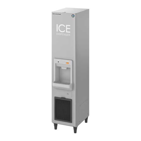
- Page 1 CUBE ICE DISPENSER DIM-40DE-HC SERVICE MANUAL...
-
Page 2: Table Of Contents
CONTENTS PAGE I. GENERAL INFORMATION -------------------------------------------------------------------------- 1 1. DIMENSIONS/CONNECTIONS ---------------------------------------------------------------- 1 2. CONSTRUCTION ---------------------------------------------------------------------------------- 2 [a] OVERVIEW ------------------------------------------------------------------------------------- 2 [b] WATER CIRCUIT AND MACHINE COMPARTMENT ---------------------------------- 3 II. CONTROLLER BOARD ----------------------------------------------------------------------------- 4 1. CONFIGURATION --------------------------------------------------------------------------------- 4 [a] CONTROLLER BOARD LAYOUT ------------------------------------------------------------ 4 [b] INPUT/OUTPUT LAYOUT ---------------------------------------------------------------------- 5 [c] BEFORE CHECKING CONTROLLER BOARD ---------------------------------------- 6 [d] SWITCH OPERATION ----------------------------------------------------------------------- 7... - Page 3 III. OPERATING INSTRUCTIONS ---------------------------------------------------------------- 38 1. IN CASE OF DIRTY WATER ------------------------------------------------------------------------ 38 2. PREPARING THE ICE DISPENSER FOR LONG STORAGE ----------------------- 38 IV. MAINTENANCE INSTRUCTIONS ------------------------------------------------------------ 39 1. MACHINE EXTERIOR, SPOUT, ICE STATION ---------------------------------------------- 39 2. AIR FILTER -------------------------------------------------------------------------------------------- 39 DRAIN PAN, STORAGE BIN, FRONT PANEL ------------------------------------------- 40 4.
- Page 4 12. CONTROLLER BOARD ------------------------------------------------------------------------ 65 [a] MODIFICATION ------------------------------------------------------------------------------ 65 [b] REPLACEMENT ----------------------------------------------------------------------------- 66 13. THERMISTOR FOR CUBE CONTROL ---------------------------------------------------- 67 14. FAN MOTOR -------------------------------------------------------------------------------------- 68 15. GEAR MOTOR ----------------------------------------------------------------------------------- 68 16. BIN CONTROL SWITCH ----------------------------------------------------------------------- 69 17. PUSH BUTTON SWITCH AND PILOT LAMP -------------------------------------------- 70...
-
Page 6: Construction
2. CONSTRUCTION [a] OVERVIEW Top Panel Nameplate Front Panel Push Button Pilot Lamp Spout Power Switch Ice Station Air Filter Removable Side Access Panel Switch Cover Louver... -
Page 7: [B] Water Circuit And Machine Compartment
[b] WATER CIRCUIT AND MACHINE COMPARTMENT Water Valve Accumulator Water Supply Pipe Evaporator Pump Motor Water Tank Drain Pan Actuator Motor Bin Control Switch Gear Motor Auger Drain Outlet Drain Hose Control Box Rear Access Panel Power Switch Compressor Hot Gas Valve Air Guide Drier Condenser... -
Page 8: Controller Board
II. CONTROLLER BOARD 1. CONFIGURATION Part Number P01873-02 Evaporator Electroless Nickel Plated [a] CONTROLLER BOARD LAYOUT Main Board Sub Board Combination... -
Page 9: [B] Input/Output Layout
[b] INPUT/OUTPUT LAYOUT Hall IC Input XA Connector (4P) Bin Control Switch / Pressure Switch / Condenser Thermistor Input XA Connector (6P) Cube Control Thermistor Input XA Connector (2P) 7-Segment Double- Digit Display Data Input/Output PA Connector (8P) Reset Button 10.5V AC Input VH Connector (2P) Close Button Open Button... -
Page 10: [C] Before Checking Controller Board
[c] BEFORE CHECKING CONTROLLER BOARD Check the power source voltage and the components as shown in the table below. Component Procedure Normal 1. Thermistor 5 -7 kilohms NOTICE (on evaporator) Thermistor sensor part is fragile, Holder glass sealed. Handle with care. Screw * Disconnect the connector CN13 on the board. -
Page 11: [D] Switch Operation
[d] SWITCH OPERATION 1) The following is the switch operation flow in different modes. When pressed and released, the switch detects the operation by its pressing duration. Water pan opens (initial cycle) Freeze setting mode Freeze setting mode Normal mode Maintenance mode (press 3s) Display mode (press 3s) Flush mode (press 3s) -
Page 12: Operation
To clear the current model code information and enter the model setting mode, press the service 1 and service 2 switches together for 15 seconds while the model code is indicated in the display mode (see “3. [c] DISPLAY MODE”). Model setting Return to mode... -
Page 13: [C] Defrost Cycle
3) The opening backup timer starts counting when the water pan starts to open. If the hall IC does not turn on within 3 minutes, the display shows “EE” and the unit stops for 60 minutes. If the error recurs after the unit resumes operation, the display shows “EE”... -
Page 14: [E] Freeze Cycle
[e] FREEZE CYCLE 1) When the water pan closes and the hall IC turns on, the water valve opens to supply icemaking water for a specific time. The icemaking water supply time varies between startup, reset, and the end of bin control cycle. * The icemaking water supply time and additional water supply time are adjustable in the maintenance mode (see “3. -
Page 15: [F] Freeze Completion Control
[f] FREEZE COMPLETION CONTROL 1) The target integrated values (cube control thermistor temperature and freeze cycle time) are set for freeze completion. * The target integrated freeze completion temperature and time are adjustable in the maintenance mode (see “3. [b] MAINTENANCE MODE”). 2) After the cube control thermistor senses a temperature below 0°C, the cube control thermistor temperature and freeze cycle time are integrated every second. - Page 16 2) Summer 1) Spring/fall Dimple size 5mm Smaller dimple size -18°C -18°C Freeze cycle time (min) Freeze cycle time (min) 3) Winter Larger dimple size -18°C Freeze cycle time (min) Comparison of the evaporator temperature curves finds that the red-colored area varies in different seasons.
- Page 17 This area corresponds to the energy on ice. Making these different areas into one can equalize the dimple size. To calculate the energy required for ice production, the actual ice production area under 0°C in the evaporator temperature curve is approximated into a triangle. This area can be calculated by Time x temperature ÷...
-
Page 18: [G] Water Supply Control
[g] WATER SUPPLY CONTROL 1) When the water pan closes and the hall IC turns on, the water valve opens to supply icemaking water for a specific time. The icemaking water supply time varies between startup, reset, and the end of bin control cycle. * The icemaking water supply time and additional water supply time are adjustable in the maintenance mode (see “3. -
Page 19: [J] Bin Control Cycle
[j] BIN CONTROL CYCLE 1) When the bin control switch stays on for more than 10 seconds, the bin control cycle starts, and the icemaker stops. After the bin control switch stays off for more than 80 seconds, the bin control cycle ends and the icemaker restarts. (The hot gas valve opens 30 seconds before the icemaker restarts.) 2) After the bin control cycle ends (or when the power supply is turned on), the water pan starts to open (if the icemaker stopped while the water pan was closing). -
Page 20: [L] 7-Segment Led
[l] 7-SEGMENT LED 1) When the power supply is turned on, the display shows “on” and the automatic icemaking process starts. 2) When an error occurs, the display flashes the applicable error code. 3) In the maintenance mode, the display shows various settings. 4) In the display mode, the display shows various values and the error history. -
Page 21: Mode Setting
3. MODE SETTING [a] WATER CIRCUIT FLUSH MODE 1) When the service 2 switch is pressed for 3 seconds during operation, the water circuit flush mode starts. The ones digit in the LED display lights up as follows. 2) There is no 30-second standby time after the power supply is turned on. While the compressor stays off, the actuator motor starts to open the water pan. -
Page 22: [B] Maintenance Mode
[b] MAINTENANCE MODE When the reset switch is pressed for more than 3 seconds, the maintenance mode starts to allow various set values to be checked or adjusted. 1) Press the reset switch for more than 3 seconds while the unit is running. The display shows “1”. - Page 23 Maintenance Mode List Item Range Step 1 Defrost completion temp 2 to 20°C 2 Integrated constant 1 (temp) -5 to -40°C 3 Integrated constant 2 (time) 5 to 90 min 4 Ambient temp correction operating 10 to 50°C Basic temp for integrated value 5 Ambient temp correction rate for 10 to 100% (00 = 100) integrated value...
- Page 24 Maintenance Mode Descriptions Item Description 1 Defrost completion temp Temperature to complete defrost cycle (detected by cube control thermistor). 2 Integrated constant 1 Target integrated value inside controller board is (temp) determined by constants 1 and 2. Temperature in freeze cycle is integrated, and freeze cycle continues until target integrated value is reached.
- Page 25 Item Description 15 Additional icemaking Time to supply additional icemaking water water supply time required after pump motor starts following normal icemaking water supply time (it is deactivated on this model). 17 Defrosting water control Selection of defrosting water control. When Water supply set to “0”, normal control as described for No.
- Page 26 Item Description Time to keep hot gas valve closed after 20 sec 73 Hot gas valve off time in defrost cycle. Prevent ice bridge in bin by Ice bridge delaying ice dropping time (it is deactivated on this model). Low temp in Upper temperature limit at the beginning of 74 Operating temp defrost cycle...
- Page 27 Maintenance Mode Settings DIM-40DE-HC Item Nickel Plated 1 Defrost completion temp 2 Integrated constant 1 (temp) 3 Integrated constant 2 (time) 4 Ambient temp correction operating temp Basic for integrated value 5 Ambient temp correction rate for integrated value 6 Freeze backup timer 10 Defrosting water supply time, water temp less than 13°C...
-
Page 28: [C] Display Mode (Log Clearing)
[c] DISPLAY MODE (LOG CLEARING) When the service 1 switch is pressed for more than 3 seconds, the display mode starts to allow various items and logs to be checked, displayed or cleared. Press the service 1 switch for more than 3 seconds while the unit is running. The display shows “n1”. -
Page 29: [D] Model Code Setting Mode
Item Description Clear Display up to 5 errors from latest to oldest for 1 sec h4 Error log ON, 0.5 sec OFF, “- -” at the end, then back to latest error. In case of less than 5 errors, display oldest error, “- -”, then back to latest one. - Page 30 Controller Board P01873-02 <Controller board replaced> <Chosen model code displayed> <Model code memorized> Model Code List Model Digit Digit DIM-40DE-HC...
-
Page 31: Segment Display
4. 7-SEGMENT DISPLAY [a] NORMAL MODE Item Display Power on Defrost cycle Freeze cycle Bin full Display range from -5.0 to -40.0 Freeze temp setting Flash E1: Abnormal freeze cycle E2: Abnormal defrost cycle EE: Other Error code (See “5. ERROR CODES”) Water circuit lush [b] MAINTENANCE MODE... - Page 32 Item Display (example) 5 Ambient temp correction 100% (last 2 digits rate for integrated value only) 6 Freeze backup timer Same as No. 3 10 Defrosting water supply Same as No. 3 (unit: sec) time, water temp less than 13°C 11 Defrosting water supply Same as No.
-
Page 33: [C] Display Mode
[c] DISPLAY MODE Item Display (example) – n*, h* n1 Freeze cycle time count 21 min or 21% 100% (last 2 digits only) up (min) n2 Freeze cycle completion rate (%) n3 Current cube control -19°C 24°C thermistor temp n4 Current ambient thermistor temp n5 Water temp (presumed) Water temp 13°C or more... -
Page 34: Error Codes
5. ERROR CODES [a] ERROR CODES, CAUTION CODES * When the controller board detects an error, the display shows one of the following errors, caution and alarm codes in the display mode. Operation depends on the type of error. * The error and caution codes other than E1 and E2 are indicated as “EE” or “EF” in the 7-segment display at the time of occurrence. -
Page 35: [B] Service Diagnosis
[b] SERVICE DIAGNOSIS Error Check Possible Cause Remedy Water valve Closing failure Clean or replace Gas leak Repair Refrigeration circuit Clogged capillary Replace heat exchanger Clogged expansion valve Replace Defective Replace Compressor Check supply voltage or replace Starting failure electrical components Compressor relay Coil circuit open Replace... -
Page 36: Troubleshooting
6. TROUBLESHOOTING IMPORTANT If receiving a service call, ask the user to turn off the power to the ice dispenser and turn it on again, while watching the ice dispenser. This will reset the controller, and in some cases normal operation will resume. [a] INSTRUCTIONS FOR SERVICE ENGINEER 1) Check that the icemaker has been earthed properly. -
Page 37: Removal And Replacement
7. REMOVAL AND REPLACEMENT The replacement controller board is in common use for the entire IM_N models (HE). To replace: 1) Unplug the icemaker or disconnect the power source. 2) Remove the front panel and control box cover. 3) Disconnect all the connectors from the controller board. Remove the controller board from the control box. - Page 38 To check the current memorized model code, view in the display mode (press and hold the service 1 switch for 3 seconds – the display changes to “n1”, then press the service 1 switch several times to find "h6", then press the reset switch and the memorized code appears in the display).
- Page 39 Ice production at normal temperature (RT 15°C, WT above 13°C) [Y(S1] Initial cycle Freeze cycle Defrost cycle Freeze cycle Soft start Compressor Max 95s 10s Water valve Actuator motor Down Hot gas valve Pump motor Fan motor Bin control switch ompletion temp.
- Page 40 Ice storage at normal temperature (RT 15°C, WT above 13°C) Freeze cycle Defrost cycle Bin control cycle Defrost Freeze cycle cycle Compressor Water valve Actuator motor Down Hot gas valve Pump motor Fan motor Bin control switch Defrost completion temp. Cube control 0°C thermistor temp.
- Page 41 Notes on timing charts (*1, *2, *3) DIM-40DE-HC *1 Defrosting water supply time (water temp less than 13°C, or initial cycle) *1 Defrosting water supply time (water temp 13°C or more) *2 Icemaking water / additional water supply time 22/0s 1) When the power is turned on or the unit resumes operation after a bin control cycle, the water temperature is considered less than 13°C and the water valve opens for 15...
-
Page 42: Operating Instructions
III. OPERATING INSTRUCTIONS 1. IN CASE OF DIRTY WATER 1) Remove the switch cover and turn off the power switch. 2) Close the water supply tap. Unscrew and lift off the front panel. See Fig. 1. 4) Wait for 5 minutes and turn on the power switch. 5) Forty seconds after the icemaking compartment starts operation, turn off the power switch immediately to drain the water tank. -
Page 43: Maintenance Instructions
IV. MAINTENANCE INSTRUCTIONS WARNING 1. Before carrying out any cleaning or maintenance operations, unplug the ice dispenser from the electrical supply network. 2. This appliance must not be cleaned by use of a water jet. CAUTION Before handling or using cleaning solutions, check the guidelines on the product for advice on suitable personal protective clothing, gloves, goggles, etc. -
Page 44: Drain Pan, Storage Bin, Front Panel
NOTICE After cleaning, be sure to place the air filter back in position. 3. DRAIN PAN, STORAGE BIN, FRONT PANEL 1) Follow the steps 1) to 2) in “III. 2. PREPARING THE ICE DISPENSER FOR LONG STORAGE”. 2) Unplug the ice dispenser. 3) Pull out the drain pan hose from the drain hole in the storage bin. -
Page 45: Water Valve
WATER VALVE Follow the steps 1) to 2) in “III. 2. PREPARING THE ICE DISPENSER FOR LONG STORAGE”. Unplug the ice dispenser or disconnect the power source. Close the water supply tap. Remove the top panel and front panel. Disconnect the inlet hose from the water valve. Remove the mesh filter from the water valve. -
Page 46: Icemaking Water System
Always wear rubber gloves, eye protectors, apron, etc. for safe handling of the cleaner and sanitizer. NOTICE 1. Use the cleaners and sanitizers recommended by Hoshizaki. Contact your local Hoshizaki office for further details. (The instructions below give an example of those recommended cleaners and sanitizers.) 2. - Page 47 13) Use a suitable container to dilute 44 ml of 5.25% sodium hypochlorite solution with 11.4 lit. of water. * Alternatively use the Hoshizaki recommended sanitizer as directed by the relevant instructions. Close the water supply tap. Plug in the ice dispenser or connect the power source.
- Page 48 17) Open the water supply tap, and repeat the above step 8), then step 10). Plug in the ice dispenser. 18) Repeat the above step 17) at least three times to rinse thoroughly. 19) Plug in the ice dispenser or connect the power source. Check for proper icemaking operation.
-
Page 49: Technical Information
V. TECHNICAL INFORMATION 1. WATER CIRCUIT AND REFRIGERANT CIRCUIT Capillary Tube Evaporator Water Accumulator Valve Controller Actuator Board Motor Pump Motor Bin Control Switch Ice Station Water Tank Trap Drain Pan Storage Bin Drain Outlet U Trap Condenser Hot Gas Drier Valve Motor... -
Page 50: Wiring Diagram
2. WIRING DIAGRAM WIRING DIAGRAM POWER SUPPLY SEE NAMEPLATE TUBE CONTROL FOR POWER VOLTAGE REQ CONTROLLER BOARD GR/Y THERMISTOR GROUND NEUTRAL LIVE (BK) GR/Y (BK) CN13 BIN CONTROL FUSE SWITCH VARISTOR (BK) Y TRANSFORMER BU CAP. (BR) FUSE START 6.3A (BK) RELAY SURGE... -
Page 51: Performance Data
(kg/d) 39.1 (43.2) 34.2 (37.2) 26.6 (30.2) 20.5 Freeze Cycle Time (min) 20.0 23.9 32.7 43.6 Defrost Cycle Time (min) DIM-40DE-HC Water Consumption (lit/h) Electric Consumption Head Pressure [peak] (bar) Note: The sound output of this appliance is below 70dB. -
Page 52: Service Diagnosis
VI. SERVICE DIAGNOSIS 1. NO ICE PRODUCTION PROBLEM CHECK POSSIBLE CAUSE REMEDY [1] The ice a) Power source 1. OFF position. 1. Move to ON position. 2. Loose connections. 2. Tighten. dispenser will 3. Bad contacts. 3. Check for continuity and not start. - Page 53 PROBLEM CHECK POSSIBLE CAUSE REMEDY [2] (Continued) f) Air filter, 1. Clogged. 1. Clean. condenser [3] Compressor a) Control circuit 1. Loose connection or 1. Repair or replace. runs, but other broken wire. components will not start. [4] Fan motor will a) Wiring 1.
-
Page 54: Low Ice Production
2. LOW ICE PRODUCTION PROBLEM CHECK POSSIBLE CAUSE REMEDY [1] Freeze cycle a) Water supply 1. Low pressure. 1. Check for recommended time is too pressure. b) Water 1. Too high. 1. Check for recommended long. temperature water temperature. c) Water quality 1. -
Page 55: Others
PROBLEM CHECK POSSIBLE CAUSE REMEDY [2] (Continued) f) Pump motor 1. Leaks. 1. Replace. 2. Bearings worn out. 2. Replace. g) Thermistor, 1. See “II. CONTROLLER BOARD”. controller board [3] Slab does a) Extension spring 1. Over-extended. 1. Replace. b) Clearance 1. -
Page 56: Removal And Replacement Of Components
VII. REMOVAL AND REPLACEMENT OF COMPONENTS 1. PANELS FRONT PANEL Remove the louver and turn off the power switch. Remove the screw securing the bottom of the front panel. Remove the front panel. See Fig. 1 in “III. 1. IN CASE OF DIRTY WATER”. 4) Disconnect the drain hose from the ice station. -
Page 57: [D] Refrigerator Covers
1) Remove the four machine screws securing the air guide to the cabinet. 2) To refit the air guide, reverse the above procedure. [d] REFRIGERATOR COVER The refrigerator cover is located on top of the machine compartment as a partition and fitted with the control box. -
Page 58: Service For Refrigerant Lines
2. SERVICE FOR REFRIGERANT LINES Only trained service engineer can service the R290 refrigeration unit. [a] SERVICE INFORMATION Allowable Compressor Opening Time and Prevention of Lubricant Mixture [R290] The compressor must not be opened more than 30 minutes in replacement or service. Do not mix lubricants of different compressors even if both are charged with the same refrigerant, except when they use the same lubricant. -
Page 59: [B] Refrigerant Recovery
Replacement Copper Tubing [R290] The copper tubes currently in use are suitable for R290. But do not use them if oily inside. The residual oil in copper tubes should be as little as possible. (Low residual oil type copper tubes are used in the shipped units.) Evacuation, Vacuum Pump and Refrigerant Charge [R290] Never allow the oil in the vacuum pump to flow backward. -
Page 60: [C] Evacuation And Recharge
[d] EVACUATION AND RECHARGE 1) Attach charging hoses, a service manifold and a vacuum pump to the system. If possible, use quick release connectors onto the access valves (especially on the high side). 2) Turn on the vacuum pump. 3) Allow the vacuum pump to pull down to a 760-mmHg vacuum. Evacuating period depends on the pump capacity. -
Page 61: Compressor
WELDING REPAIR FOR R290 REFRIGERATION CIRCUIT Make sure the surrounding area of the unit to be repaired is free from ignition sources. Open the window or operate the ventilator to make the surrounding well-ventilated. Connect the piercing valve. Recover the refrigerant in the specified manner or discharge it into the atmosphere. -
Page 62: Drier
17) Replace the front panel and rear mesh in their correct positions. 18) Plug in the ice dispenser or connect the power source. Note: Hoshizaki recommends that compressor starting electrics are always replaced at the same time as the compressor. -
Page 63: Evaporator
8) Evacuate the system and charge it with refrigerant (See “2. [c] EVACUATION AND RECHARGE”). 9) Replace the rear mesh in its correct position. 10) Plug in the ice dispenser or connect the power source. Note: Always use a drier of the correct capacity and refrigerant type. 6. -
Page 64: Hot Gas Valve
7. HOT GAS VALVE IMPORTANT Always install a new drier every time the sealed refrigeration system is opened. Do not replace the drier until after all other repair or replacement has been made. 1) Unplug the ice dispenser or disconnect the power source. 2) Remove the rear mesh panel. -
Page 65: Water Pan Assembly
8. WATER PAN ASSEMBLY Remove the top panel and front panel. Remove the front panel and push the reset switch on the control box to open the water pan. 3) Unplug the ice dispenser or disconnect the power source. 4) Disconnect the pump motor leads in the wiring channel. 5) Remove the two extension springs from the cam arms. -
Page 66: Pump Motor
9. PUMP MOTOR 1) Unplug the ice dispenser or disconnect the power source. Remove the top panel and front panel. 3) Disconnect the pump motor leads in the wiring channel. 4) Remove screws and the pump motor from the bracket. 5) Disconnect the pump suction and discharge tubing. -
Page 67: Actuator Motor
11. ACTUATOR MOTOR Remove the top panel and front panel. 2) Push the reset switch on the control box to open the water pan. 3) Unplug the ice dispenser or disconnect the power source. 4) Remove the extension spring (actuator motor side) from the cam. 5) Disconnect the actuator motor leads in the wiring channel. -
Page 68: Cam Arm
12. CAM ARM [a] CAM ARM (A) - ACTUATOR MOTOR SIDE Refer to “10. ACTUATOR MOTOR”. [b] CAM ARM (B) - REAR SIDE Remove the top panel and front panel. Remove the front panel and push the reset switch on the control box to open the water pan. - Page 69 Fig. 11...
-
Page 70: Controller Board
ICEMAKING ASSEMBLY AND CAM MECHANISM INDEX NO. DESCRIPTION Water Pan Assembly Actuator Motor Actuator Motor Bracket Cam Arm (A) Cam Arm (B) Cam Shaft Cam Shaft Bearing Water Pan Bearing (A) Water Pan Bearing (B) Spring Pin Extension Spring Mechanism Base Flange Nut Clamp Insulation... -
Page 71: [B] Replacement
[b] REPLACEMENT 1) Unplug the ice dispenser or disconnect the power source. Remove the front panel. 3) Remove screws and the control box cover. 4) Pull out and remove the controller board from the control box. 5) Install the new controller board and reassemble the control box in the reverse order of the removal procedure. -
Page 72: Thermistor For Cube Control
14. THERMISTOR FOR CUBE CONTROL 1) Unplug the ice dispenser or disconnect the power source. 2) Remove the top panel, front panel and pipe cover (rear). 3) Remove the connector K4 on the controller board, referring to “12. [b] REPLACEMENT”. 4) Unscrew and remove the thermistor holder and thermistor, located on the evaporator (front side). -
Page 73: Fan Motor
15. FAN MOTOR 1) Unplug the ice dispenser or disconnect the power source. Remove the front panel. 3) Remove the control box and air guide. 4) Disconnect the connector of the fan motor. 5) Remove the fan motor bracket and the fan motor. 6) Cut the leads of the fan motor allowing enough lead length to reconnect using closed end connectors. -
Page 74: Bin Control Switch
Machine Screw (Motor Bracket) Motor Bracket Machine Screw (Ice Guide) Machine Screw (Motor) Ice Guide Auger Gear Motor Spring Pin Joint Motor Cover View with motor cover removed Fig. 14 17. BIN CONTROL SWITCH 1) Insert a flat blade screwdriver between the switch case and switch base, and lightly pry the switch case off. -
Page 75: Push Button Switch And Pilot Lamp
18. PUSH BUTTON SWITCH AND PILOT LAMP 1) Unplug the ice dispenser. Remove the front panel. If the push button switch does not require replacement, skip 3) - 11). 3) Remove the connectors to the push button Push Button Plunger Supporter switch.