
Related Manuals for Raymarine 465


Summary of Contents for Raymarine 465
- Page 1 Distributed by Any reference to Raytheon or RTN in this manual should be interpreted as Raymarine. The names Raytheon and RTN are owned by the Raytheon Company.
- Page 3 Echo Sounding Your eyes underwater An “echo sounder” or “sonar” unit sends high-frequency sound waves down into the water below a boat. These sounds hit the bottom of the lake or sea and bounce back. The display unit measures the time delay as the signal goes out and returns. The FishFinder uses this information to display a graphic image of the bottom conditions.
-
Page 4: Features And Functions
“Out of the box” operation Because of a number of automatic fea- tures, the FishFinder 465 unit is ready to operate “right out of the box.” This unit in- cludes automatic settings for the most important controls – range, sensitivity, and zoom. - Page 5 Before you begin This manual contains very important information on the installation and operation of your FishFinder 465. For best results as you use this unit, please take the time to read this manual thoroughly. IMPORTANT NOTICE THIS DEVICE IS ONLY AN AID TO NAVIGATION. ITS ACCURACY CAN...
- Page 6 FishFinder 465 Instruction Manual...
-
Page 7: Table Of Contents
Contents Echo sounding – How it works (inside front cover) FishFinder 465 – Features and functions i For information and service ii Introduction 1 About the FishFinder 465 1 System Components 2 Standard Equipment 2 Standard Transducers 2 Optional Accessories 2... - Page 8 Operating Pages 29 FishFinder Page 31 Choosing a Frequency 36 Fish Indications 37 Bottom Indications 38 Window Page 40 Sidelooker Page 42 Digital Page 46 Performance Modes 49 Zoom Mode 49 A-Scope (Bottom Coverage) Mode 51 Bottom Lock Mode 53 Setup Instructions 55 The Setup Menu 55 Range Setting 56...
- Page 9 Sidelooker Sensitivity Menu Item 77 Sidelooker Chart Speed Menu Item 77 Sidelooker View Menu item 78 Combining Displays 79 Resetting the Unit to Factory Defaults 80 Default Settings 81 Maintenance and Troubleshooting 82 Cleaning Instructions 82 Troubleshooting Suggestions 82 Servicing a Thru-Hull Transducer 86 How to Contact Apelco 86 Specifications 89 General Information 89...
- Page 10 List of Figures Figure Unit in Use Front Panel Typical Installation Transducer Types Assembling the Transducer Bracket Transducer Mounted on Transom Transducer Bracket, Side View Correct Mounting Position Mounting the Transducer Installing the Sidelooker Transducer Suppression Ferrites Installation on Bracket 2-10 Dimensions 2-11...
- Page 11 Reaching the System Setup Menu System Setup Menu 4-10 Zoom Select Menu Item 4-11 Zoom Screen Split/Full Menu Item 4-12 Bottom Lock Range Menu Item 4-13 Bottom Lock Split/Full Menu Item 4-14 Digital Setup Menu Item 4-15 Sidelooker Range Menu item 4-16 Sidelooker Sensitivity Menu Item 4-17...
-
Page 12: Introduction
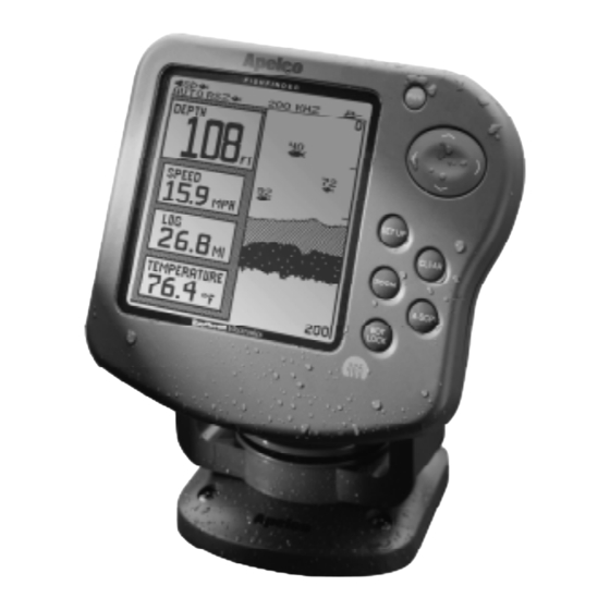
• measure the speed of the boat and the distance traveled • show the water temperature We are sure you will find the FishFinder 465 to be one of the most useful devices on your boat. FishFinder 465 Display Unit... -
Page 13: System Components
DC power cable Instruction manual Four #10 x 3/4” ss mounting screws Standard Transducers Depending on which model of the 465 you have purchased, the box will include one of the transducers listed below: Description Transom-mount transducer (with speed and temperature sensors, including... - Page 14 Transom-mount speed and temperature sensor (used with depth-only transducers M78922, M78928, M78946) Replacement transom transducer mounting bracket kit Transducer switch box (select between two 465 FishFinder displays, using one transducer) Replacement paddle wheel kit (for transom- mount transducer) Replacement paddle wheel kit...
-
Page 15: Installation
2 – Installation The installation process has four parts: • Mounting the transducer • Mounting the display unit • Connecting the cables for the transducer and power supply • Calibrating the display unit About the Transducer Several different kinds of transducers can be used with this unit. The transom-mount type is used most often. -
Page 16: Selecting The Correct Type Of Transducer
Transom-mount Thru-hull transducer transducer In-hull Sidelooker transducer transducer Selecting the Correct Type of Transducer Before you begin the installation, double-check to be sure you have the correct type of transducer. Each kind of transducer is designed for a particular type of use. In this manual we will include detailed mounting instructions for the transom-mount transducer. -
Page 17: Assembling The Transducer Bracket
Use a trolling motor transducer if – you want to attach the transducer to a trolling motor. Use a Sidelooker transducer if – you need a way of searching for fish on either side of the boat. This type of transducer is attached to the bracket of the transom-mount transducer. Assembling the Transducer Bracket Fit together the two parts of the transducer bracket as shown in Fig. -
Page 18: Transducer Mounted On Transom
Allow a clearance of at least 10 inches (254 mm) 10" (254 mm) propeller from damaging the transducer when it is turned. • Do not mount the transducer behind any hull fittings, intakes, or other parts which extend from the hull. These may cause turbulence or air bubbles. -
Page 19: Correct Mounting Position
Average transom angle– no wedge necessary 2 to 5 For fiberglass hull – 1/8" to 1/4" (3.2 to 6 mm) For aluminum hull – 1/4" to 3/8" (6 to 9 mm) The bow of the transducer is above the bottom of the transom, creating cavitation. -
Page 20: Mounting The Transom-Mount Transducer
• If the boat will be carried on a trailer, be sure the transducer will not hit any rollers, bunks or fittings on the trailer. Mounting the Transom-Mount Transducer On a boat with a fiberglass hull, the leading edge of the transducer should extend 1/8"... -
Page 21: Mounting The Optional Sidelooker Transducer
Mounting the Optional Sidelooker Transducer The Sidelooker transducer allows the display unit to check the water to either side of the boat. This is helpful when you are looking for fish near river banks, or under docks or piers. The Sidelooker transducer is attached to the same mounting bracket used with the transom-mount transducer. - Page 22 For planing hulls – Install in the flat planing area near the stern. Always install forward of the propeller(s) and shaft(s). For small displacement hulls – Install near the centerline of the hull and 1/3 of the way forward from the stern. Always install forward of the propeller(s) and shaft(s).
-
Page 23: Installation Notes - In-Hull Transducer
It is very important to seal the opening around the transducer using a high-quality marine sealant suitable for underwater use. After installation, do not leave your boat in the water for any amount of time without checking for leaks. Installation Notes – In-Hull Transducer Detailed instructions for this installation will be included with the trans- ducer. -
Page 24: Installation Notes - Transducer For Speed And Temperature Only
Installation Notes – Transducer for Speed and Temperature Only This type of transducer may be used with a thru-hull transducer which reads depth only. The speed/temperature transducer is attached to the transom of the boat. Detailed instructions for this installation will be included with the transducer. -
Page 25: Suppression Ferrites
This is especially important with wiring for the boat’s ignition, alternator, or tachometer. It is also helpful to keep the transducer cable away from the FishFinder power cable. If it is necessary to run the transducer cable across any wires, make the crossing at a right angle. -
Page 26: Mounting The Display Unit - Standard Mount
To release the display from the base, press here. The display can be turned from side to side. Mounting the Display Unit – Standard Mount You may mount the display unit on any flat surface using the bracket supplied. See Fig. 2-9. (There is also an optional kit which allows you to flush-mount the display in a flat panel or dashboard). -
Page 27: Dimensions
Hole 3/16" (5 mm) 2-27/32" (72 mm) 1-3/4" (45 mm) 1-15/32" (37 mm) 1-3/4" (44 mm) 4-9/32" (109 mm) 2-25/32" (70 mm) 2-21/32" (67 mm) 6-5/8" (169 mm) 5-13/16" (147 mm) 3-29/32"(99 mm) 4-7/32"(107 mm) 8-1/4" (210 mm) Fig. 2-10 Dimensions Installation... -
Page 28: Mounting The Display Unit - Flush Mount
Mounting the Display Unit – Flush Mount In order to do this installation, you will need the optional flush mounting kit (part no. M99-138). See Fig. 2-11. Select a mounting location on the dashboard or control panel. Choose a clear, flat area at least 7" x 7" (180 mm x 180 mm). Be sure you will also have at least 6"... -
Page 29: Installing The Transducer Cable
Separate the display unit from the mounting bracket. (See Fig. 2-12.) Press the large button in the center of the bracket to separate the bracket arms. The display unit is attached to the arms by two screws. Each screw is covered by a cap. Locate the small slot beside each cap and pry upward using a small screwdriver. -
Page 30: Installing Cable On Transom
Hull projections Fiberglass: 1/4" (6mm) Aluminum: 1/2" (13 mm) Route the cable up and over the top edge of the transom. See Fig. 2-13. Secure the cable using cable clamps. (These clamps are available from your local marine equipment supplier.) If you do not want to expose the cable on the deck, you may drill a new hole (3/4"... -
Page 31: Installing The Transducer Cable - Sidelooker Option
Installation with Separate Speed and Temperature Sensors Optional depth-only and speed- and temperature-only transducers are available for the FishFinder 465. In this optional configuration the separate transducers are connected via a “Y” type receptacle cable located on the optional speed- and temperature-only transducer cable. -
Page 32: Making The Dc Power Connections
Plug the cable from the depth-only transducer into the receptacle connector on the optional speed- and temperature-only transducer. The speed- and temperature-only transducer then connects at the transducer receptacle of the FishFinder 465. This is shown below in Fig. 2-15. Sensor for... -
Page 33: Dc Power Connections
BLACK RF ground terminal (+), and the black wire to the negative terminal (-). The negative terminal may also be called “ground” or “earth.” (The display unit is internally protected if you accidentally reverse the polarity of the power wires.) Attach the red or positive wire to a 5 amp circuit breaker. -
Page 34: Calibrating The Sensors
Note – Press firmly when inserting the power cable and transducer cable to ensure a tight seal. When you press the the unit will not turn on and you suspect that you may have reversed the power connections, check the DC power lines all the way back to the battery. - Page 35 use a smaller number for Speed Cal. You may enter any value between 75 and 125. The temperature sensor is usually very accurate, but you can adjust the calibration using the entry for “Temp Cal.” Final note: After you finish the installation, please remember to fill out the Warranty Card included with this manual.
-
Page 36: Operating Instructions
3 – Operating Instructions In this section of the manual, we will explain how to operate the unit. (Setup instructions are included in the next section.) Below is a drawing of the display unit. Display area F I S H F I N D E R Controls on Display Panel The FishFinder is designed to be easy to use while the boat is moving. - Page 37 Page Control Up and down arrows – ( and ) During setup – Use these controls to call up a choice or move to the next line on a menu. If the Zoom display is turned on – If the manual zoom feature is turned on, these will move the zoom display up or down.
-
Page 38: Turning The Power On And Off
The “Bottom Lock” Mode shows a “bottom-up” view. The LOCK bottom is used as a reference, and all depths are measured from the bottom up. For more information, see the section on “Performance Modes” on page Turning the Power On and Off Press the button once to turn on the power. -
Page 39: Lamp/Contrast Display
Adjust lamp brightness The 465 FishFinder has a backlit display and keypad. This feature allows you to use the unit at night. The backlight for the display is adjustable to five levels of brightness. To turn the lamp on or adjust the brightness, use the <... -
Page 40: Operating Pages
CLEAR FishFinder Page. Operating Pages The 465 FishFinder has four “pages,” or normal displays. These can be used to show different kinds of information. Here is a list of the pages: Mode FishFinder Page... -
Page 41: Operating Pages
Lamp/Contrast Menu FishFinder Page CLEAR Sidelooker Page Window Page (Only if Sidelooker feature is turned on) Digital Page Fig. 3-3 Return to Operating FishFinder Pages Page Operating Instructions... -
Page 42: Fishfinder
FishFinder Page Fish alarm set Shallow alarm set Deep alarm set Buzzer symbol Auto features on Speed Log/distance Water temperature Bottom indication Bottom depth Figure 3-4 shows a typical FishFinder display. (The FishFinder Page is also called the “chart” or “bottom graph” display.) As time passes, this display scrolls from right to left. - Page 43 “chart speed.” You can adjust this using the “Setup Menu.” (See Section 4.) Many of the items on this display appear in the other display pages. Since you are likely to use the FishFinder Page most often, we will explain all of these items here. Top of display Buzzer symbol This symbol shows whether any of the alarms will use the...
- Page 44 Fish alarm set The FishFinder also has an alarm which will sound whenever it detects a fish. When this alarm is set, the fish symbol appears at the top of the display. If the alarm is triggered and the buzzer has been turned on (in the System Setup Menu), the buzzer will sound for a moment.
- Page 45 the unit to use both frequencies at the same time (“dual frequency”), or even display both frequencies at once (“split screen”). Auto frequency on (A) An “A” indication here shows that the unit is choosing the frequency automatically. (For more on this, see “Choosing the Frequency.”) Boat symbol This symbol is always turned on.
- Page 46 From the System Setup Menu, you can turn this item off or change the units used for this display. Fish symbol This indicates that the FishFinder sees a fish. Generally, the larger the fish symbol appears, the larger the fish. (The size of the fish symbol actually depends on a number of factors.
-
Page 47: Choosing A Frequency
Choosing a Frequency We said that the FishFinder uses sound waves to “see” through the water under the boat. The “frequency” is a measure of how fast the sound waves change or “vibrate.” The FishFinder uses sound waves with two different frequencies –... -
Page 48: Fish Indications
There is really nothing very solid for the sound waves to bounce off of. The FishFinder 465 is very good at telling the difference between a fish and the surrounding water. In fact, Apelco is the leader in this technology. -
Page 49: Bottom Indications
fish symbols on the display. A fish with a large air sac will produce a large fish symbol, while a fish with a small sac will produce a small symbol. The symbol also indicates which of the two frequencies was used to locate the fish. -
Page 50: Bottom Conditions
Soft (Mud) reach through this layer, and may be reflected by a more solid layer below. It is also possible that the sound waves are making two complete trips – hitting the seabed, bouncing off of the bottom of the boat, then reflecting off the seabed again. -
Page 51: Window
Window Page The Window Page is a flexible feature which allows you to combine several different kinds of information on the display of the unit. See Fig. 3-7. The right side of the Window Page is a half-screen version of the Fish- Finder Page. -
Page 52: Options For Window Page
Option A Option C Option E Option G Operating Instructions Option B Option D Option F Option H Fig. 3-8 Options for Window Page... -
Page 53: Sidelooker
The digital displays in Window options A, B, C, D, and E all behave identically to the corresponding ones in the full-screen Digital Page (see page 46). The sidelooker displays in Window options F, G, and H all behave identically to those in the full-screen Sidelooker Page (see page 43). These options will only be displayed if the Sidelooker feature is enabled. - Page 54 The optional Sidelooker transducer transmits two acoustic beams-one to the port side of the boat, and one to the starboard. These are displayed on the left and right halves of the Sidelooker Page. See Fig. 3-9. Once the Sidelooker feature has been turned on, you can reach the Sidelooker page easily.
- Page 55 Underwater objects such as tree stumps or rocks can also be detected by the Sidelooker transducer. These objects usually appear as thicker vertical targets. The Sidelooker sounding beam is transmitted very close to the surface of the water. In rough or choppy water this turbulence may appear on the Sidelooker display as “noise”...
- Page 56 chosen using the entry for Depth Units in the System Setup Menu. If you have selected feet (FT) or fathoms (FA), the distance shown here will be measured in feet. If you have selected meters (M), the distance shown here will be in meters.
-
Page 57: Digital
System Setup Menu. (See page 23 for details.) The distance traveled, calculated using the signal from the paddlewheel or impeller. The 465 remembers this value after the unit is turned off, provided the unit is shut off using the button. - Page 58 the Setup Menu. (See page 46 for details.) Battery The measured DC voltage of your boat’s battery. Elapsed Time The amount of time which has passed since turning the unit on, in Hours : Minutes : Seconds. The Elapsed Time may be reset to 00:00:00 from the Setup menu when the Digital Page is visible.
-
Page 59: Performance Modes
FishFinder Page Zoom Mode ZOOM A-Scope Mode A-SCP Bottom Lock Mode LOCK Fig. 3-12 Performance Modes Operating Instructions... -
Page 60: Performance Modes
Performance Modes This unit has three “performance” modes which can be used to add to the standard FishFinder Page. These are the Zoom, A-Scope and Bottom Lock Modes. Each mode presents the raw information from the transduc- ers in a special way. To reach one of these modes, press the correspond- ing button on the unit. - Page 61 Many of the items presented by the Zoom Mode are the same as those on the FishFinder Page. There are a few additional items: Zoom magnification This indicates the amount of “zoom” or magnification. You always set the amount of zoom manually. While the Zoom screen is visible, press Zoom Menu, shown in Fig.
-
Page 62: A-Scope (Bottom Coverage) Mode
A-Scope (Bottom Coverage) Mode Fig. 3-14 A-Scope Mode (half screen) On the FishFinder Page the bottom graph is “drawn” after the FishFinder receives several echoes. This has the effect of showing a record of the bottom contour. The A-scope Mode shows raw sonar data directly from the transducer beam. - Page 63 create wider lines. Unlike the scrolling FishFinder Page, the A-Scope does not show a history of scans; instead, it is a “real-time” display. The shape of the A-Scope display shows the result as the sonar beam spreads as it penetrates deeper into the water.
-
Page 64: Bottom Lock Mode
Bottom Lock Mode Top and bottom of Bottom Lock range Bottom indication Bottom depth below surface The normal display on the FishFinder is a “top-down” view, as if it was seen from the surface of the water. The Bottom Lock Mode shows a “bottom-up”... - Page 65 than the selected range, then Bottom Lock will not display the bottom image. Bottom Lock Range The range for the Bottom Lock image is set independently from the master range setting for the FishFinder. This “Bottom Lock Range” is measured up from the bottom, rather than down from the surface.
-
Page 66: Setup Instructions
4 – Setup Instructions The Setup Menu Press the button to enter the Setup Menu. The menu items SETUP available will change, depending on the display or combinations of displays the unit is presenting when you press the order of the menu items if you start from the normal FishFinder SET UP Range Menu... -
Page 67: Range Setting
Page. (The order will be different if you start from the Zoom or Bottom Lock Modes.) To move from one menu item to another, press the arrows of the Page Control Pad. (If you continue to press enough, you will eventually return to the same menu item which appeared originally.) The unit remembers which menu item was last used for each page, and will display that item the next time you go to the Setup Menu. -
Page 68: Sensitivity Setting
“background noise.” Use a higher sensitivity setting for deeper water, and a lower setting for shallower water. The 465 FishFinder has separate sensitivity settings for the 50kHz, 200kHz, and Sidelooker channels. On the bar graph below “Auto/Man,”... - Page 69 there is no number next to the bar graph, this tells you that the Sidelooker is being adjusted. From the menu item for the range setting, press the Control Pad. The next menu item will allow you to set the sensitivity. See Fig.
-
Page 70: Chart Speed Setting
Chart Speed Setting Most of the displays on the FishFinder show a record of the signals the unit has received. The new information appears at the right (or top) edge of the display. The older information moves toward the left (or bottom) of the display. -
Page 71: Frequency Setting
Chart speed This adjusts the speed at which the information moves across the display. Use the < and > arrows of the Page Control Pad to change the chart speed. Making the bar longer increases the chart speed. If you move the bar all of the way to the left, the FishFinder will “freeze”... - Page 72 AUTO frequency If the frequency is set to AUTO, one of the two single frequencies (200 or 50 kHz) will be automatically selected, depending on the depth of the bottom. If the bottom is deeper than 350 feet (or 60 fathoms or 100 meters), the unit will use the 50kHz frequency.
-
Page 73: Resetting The Log
If you are using one of the dual frequency (or split) selections, some of the fish may appear in the wide 50 kHz beam, but not in the narrower 200 kHz beam. Fish which appear in the narrow 200 kHz beam are located more directly under the transducer, and the symbol will be solid black. -
Page 74: System Setup Menu
System Setup Menu Note - The “System Setup Menu” is not the same as the “Setup Menu” described earlier. The “Setup Menu” includes a series of small screens, shown in Fig. 4-1. The “System Setup Menu” is a single display, which includes several different items. -
Page 75: Simulator
To change one of the items, use the Pad to move up or down in the display. This will highlight an area on the display where the unit is ready to make a change. (This is like the “cursor” on a computer.) Once you have moved to the correct line, press the < or > arrows of the Page Control Pad to change the entry. -
Page 76: Vrm
shown using a more solid area of black or gray. This feature helps to show the difference between the strong echo from the bottom and the weaker echoes from fish or weeds near the bottom. The image shown in Fig. 3-4 is presented with the White Line feature turned on. -
Page 77: Temp Cal
unit says that you are moving faster than you really are, you can adjust the Speed Cal figure to a smaller number. If the unit says that you are moving slower than your actual speed, use a larger number for Speed Cal. The setting can range between 75 and 125. -
Page 78: Deep Alarm
To turn this feature off, press the < control until the display indicates zero feet, fathoms or meters. When these values are displayed in the Shallow Alarm “pop up” window, you will notice that the menu item in the System Setup Menu will read “Off.”... -
Page 79: Buzzer
operating with dual frequencies, the buzzer will produce two tones—one right after the other. If a fish has been detected by the 200 kHz beam, a high tone will be followed by a lower tone. If the fish is detected by the 50 kHz beam, the low tone will sound first, followed by the higher one. -
Page 80: Depth Units
Depth Units This item sets the units used by the depth display. You can choose feet (FT), fathoms (FA), or meters (M). Use the < and > controls to make your choice. Speed Units This item sets the units used by the speed display. The same units are used for the distance (“log”) display. -
Page 81: Setup Menus For Zoom Mode
Setup Menus for Zoom Mode The “Zoom” setup menus allow you to customize the Zoom feature to your particular application. When the unit is in the Zoom Mode, these two menu items are added to the existing Setup Menu of the Page currently selected. -
Page 82: Zoom Screen Split/Full Menu Item
Manual Zoom If you select Manual Zoom, you can choose the position of the zoom area yourself. Use the < and > arrows of the Page Control Pad to select Manual Zoom. Once you make this choice, you can set the zoom area yourself. -
Page 83: Setup Menus For Bottom Lock Mode
If you are done with your setup changes, press the back to the normal display. If you press the Page Control Pad this point, the next menu will be the Range menu shown in Fig. 4-1. Setup Menus for Bottom Lock Mode The Bottom Lock Setup Menus allow you to customize the Bottom Lock feature to your particular application. -
Page 84: Bottom Lock Split/Full Menu Item
If you are done with your setup changes, press the back to the normal display. To select the next menu item, press the arrow of the Page Control Pad. Bottom Lock Split/Full Menu Item When you first press the Bottom Lock button, the Bottom Lock information will appear in the left-hand part of a split screen. -
Page 85: Setup Menu For Window And Digital Pages
Setup Menu for Window Page You can choose some of the elements which are presented on the Window Page. You will recall that you can step to this pages by using the < or > controls on the Page Control Pad. See Fig. 3-3. Normally, the displays follow in this order: •... -
Page 86: Resetting From The Digital
Resetting from the Digital Page Two functions can be reset from the Digital Page. These are Elapsed Time and Log Reset. When the unit is displaying the Digital Page, press button. The unit will present a menu item showing the current SETUP reading for the log. -
Page 87: Sidelooker Range Menu Item
Press the > control until you see the Sidelooker Page. If you press while the Sidelooker Page is visible, the unit will present the menu item shown in Fig. 4-15. Sidelooker Range Menu Item Once the Sidelooker feature is turned on, the FishFinder uses two range settings: one for the standard displays, and a second for just the Side- looker feature. -
Page 88: Sidelooker Sensitivity Menu Item
Sidelooker Sensitivity Menu Item This menu item allows you to set the sensitivity for the Sidelooker feature only. (This will not change the sensitivity setting for the other display pages.) Choose Auto or Manual sensitivity. If you choose Manual sensitivity, use the <... -
Page 89: Sidelooker View Menu Item
“freeze” and hold the current display. (The depth indicator will continue to update.) If you are done with your setup changes, press the back to the normal display. To select the next menu item, press the arrow of the Page Control Pad. Sidelooker View Menu Item When the Sidelooker information is presented as a full-screen display, you can decide whether you want to show all of the Sidelooker image, or... -
Page 90: Combining Displays
Combining Displays The FishFinder 465 unit can combine displays in many different ways. This allows you to make maximum use of the display area, and choose only the information you really want. Here are some of the ways the images can be combined. -
Page 91: Resetting The Unit To Factory Defaults
Window Page with Sidelooker – You can combine a Sidelooker view with the Window Page display. Figure 4-20 shows an example where the Sidelooker view has been combined with the Zoom Mode in the Window Page. Notice that, again, the display is split vertically down the middle. -
Page 92: Default Settings
Default Settings When the FishFinder is new, it uses a number of preset “default” settings. Here is a list: Function Range Sensitivity Chart Speed Frequency Simulator Language Fish symbols White line Sidelooker Speed calibration Temp. calibration Depth digits Shallow alarm Deep alarm Fish alarm Buzzer... -
Page 93: Maintenance And Troubleshooting
5 – Maintenance and Troubleshooting Periodically check the display unit, cable, and transducer. Be sure all components are free of corrosion and are securely mounted. Check all cables for signs of chafing or abrasion. Be sure all of the connections to the boat’s DC power and ground system are clean and tight. - Page 94 will change to the factory defaults. See the default settings on page If the power wiring includes a fuse, it may be blown. Also check the circuit breaker or main battery switch. You may have reversed the power connections. Follow the DC power lines all the way back to the battery.
- Page 95 The transducer cable may be damaged. Check for any point where the wiring may be pinched or bent. Look for signs that water has gotten into the cable. If the transducer cable is damaged, the transducer and cable should be replaced as a unit. Contact Apelco for instructions.
- Page 96 for the System Setup Menu. The FishFinder will not display arches unless the boat is moving. If the boat is stopped, fish will appear on the display as straight lines. The transducer may not be aimed straight down. In order to display complete arches, the transducer must be vertical.
-
Page 97: Servicing A Thru-Hull Transducer
Apelco unit. You may also reach our Technical Support Department via the Internet. Questions may be addressed directly to: rmc_tech_apelco@raymarine.com Or, you may visit Apelco at the World Wide Web site for Raytheon Electronics: The telephone number for Raytheon Marine of Europe is (01705) 693611. - Page 98 For accessories and parts Please call 1-800-539-5539, extension 2120 or (603) 647-7530 extension 2120. Our Customer Service Department is available Monday through Friday, 8:15 . to 5:00 . Eastern Time. Please have the Apelco part number ready when calling to place an order. (See the Optional Accessory List in this manual on page 3.) If you are not sure which item you need for your Apelco unit, please contact our Technical Support Department before placing your order.
-
Page 99: Sample Mailing Label
In Europe, Apelco equipment may be returned to this address: Raytheon Marine Europe Limited Anchorage Park, Portsmouth PO3, 5TD, England Att. Service Department Prepaid U.P.S. return service The U.P.S. return label included with your Apelco unit provides free U.P.S. ground shipping to our Product Repair Center for all warranty repairs. See Fig. -
Page 100: Specifications
6 – Specifications General Information Display panel Panel dimensions No. of dots LCD contrast Backlight Operating pages Performance modes Keys Memory backup Power source Power consumption Dimensions (w/o bracket) Weight Waterproofing EMI resistance Specifications FSTN high-contrast LCD 3.8" H x 3.8" W (96 mm x 96 mm) 240 x 128 Adjustable, with temperature compensation LCD panel, adjustable... -
Page 101: Fishfinder Functions
FishFinder Functions Range FT (feet) FA (fathoms) M (meters) Zoom size Chart speed White line Alarms Reset distance log Fish symbols Output power Frequency Transducer beam angle Depth units Numerical display Water temperature Boat speed units Sensitivity Auto or manual 1500 2000 2500 x2, x4, x6, x8, auto/manual... -
Page 102: Connector Diagrams
Connector Diagrams DC power connector Transducer connector Specifications Pin 1 12V DC (+) Pin 2 Ground (-) (Connectors viewed looking toward rear of display unit.) Pin 1 Depth TX+ Pin 2 Depth TX- Pin 3 L Select Pin 4 Temp Pin 5 R Select Pin 6... -
Page 103: Glossary Of Terms
Glossary of Terms Aft: Near or toward the rear part of the boat (nautical term). Background noise: False or meaningless echo returns produced by bubbles, water turbulence, or debris Bow: The front of the boat (nautical term). Cavitation: Air bubbles in the water which affect the readings of a transducer. - Page 104 Knot: One nautical mile per hour (1.15 statute miles per hour). LCD: “Liquid Crystal Display” - A technology used to produce flat- panel displays. Nautical mile: 6076 feet Port: Left side of the boat, when facing the bow (nautical term). PVDF: “Poly Vinylidene Fluoride”...
- Page 105 Limited Warranty Certificate Apelco Marine Electronics warrants each new Product to be of sound design, good materials and workmanship, and will repair or exchange any parts proven to be defective in material and work- manship under normal use for a period of 2 years/24 months from date of sale to end user, except as provided below.
- Page 107 Document Number: G624106 Raytheon Marine Company 676 Island Pond Road Manchester, NH 03109-5420 USA TEL (603) 647-7530 FAX (603) 634-4756 http://www.raytheon.com Raytheon Marine Europe Ltd. Anchorage Park, Portsmouth Hampshire, PO3 5TD England TEL +44 (0) 1705 693611 Printed in England FAX +44 (0) 1705 694642...