
Related Manuals for Raymarine DS400


Summary of Contents for Raymarine DS400
- Page 1 DS400 & DS500 Digital Fishfinders Owner’s Handbook Document number: 81234-1 Date: December 2003 bereitgestellt von Busse-Yachtshop.de...
- Page 2 bereitgestellt von Busse-Yachtshop.de...
-
Page 3: Conventions Used
Raymarine. Warranty To register your DS400/500 Digital Fishfinder ownership, please take a few minutes to fill out the warranty registration card found at the end of this handbook. It is very important that you complete the owner information and return the card to the factory in order to receive full warranty benefits. -
Page 4: Important Information
Raymarine DS400 and DS500 Digital Fishfinders are intended for recreational fishfinding. EMC Conformance All Raymarine equipment and accessories are designed to the best industry standards for use in the recreational marine environment. Their design and manufacture conforms to the appropriate Electromagnetic Compatibility (EMC) standards, but correct installation is required to ensure that performance is not compromised. -
Page 5: Safety Notices
WARNING: Do not disconnect the transducer cable without first powering off the display unit. Removal of the transducer cable from the DS400/500 while power is turned on can cause sparks. Mount unit where it is well ventilated and free from gasoline fumes. - Page 6 DS400 and DS500 Digital Fishfinders Raymarine Products and Services Raymarine products are supported by a network of Authorized Service Representatives. Raymarine’s Technical Services representatives or your local dealer will be available to answer any questions you may have. For information on Raymarine products and services, contact either of the...
-
Page 7: Table Of Contents
Contents Preface ........................iii Important Information ..................iv Chapter 1: Overview ....................1 1.1 Introduction ..................1 Features ..................2 General ..................2 Transducer ................3 Chapter 2: Installation ..................5 2.1 Introduction ..................5 Planning the Installation ............... 5 Suppression Ferrites ............... 5 Connections to Other Equipment .......... - Page 8 DS400 and DS500 Digital Fishfinders Chapter 3: Getting Started ................27 3.1 Introduction ..................27 3.2 Powering on the Fishfinder ............27 3.3 Simulator Mode ................27 3.4 LCD Display .................. 28 3.5 Keypad Operation ................30 3.6 Selecting the Display Page ............31 3.7 Main Menu ..................
- Page 9 Transparent Menu ............... 59 PALETTE................... 59 Selection ................59 Background Color ..............59 DATA ITEMS................60 NAV. SET UP... (Navigation Data) ..........61 Chapter 6: Sounder Setup ..................63 6.1 Introduction ..................63 6.2 SOUNDER SETUP................ 63 ALARMS................... 67 Target Depth ID ..............
- Page 10 DS400 and DS500 Digital Fishfinders 7.2 Problem Solving ................77 Common Problems and Their Solutions ........77 7.3 How to Contact Raymarine ............78 On the Internet ................78 Customer Support ..............78 In the US ..................78 Accessories and Parts ............78 Technical Support ..............
-
Page 11: Chapter 1: Overview
Chapter 1: Overview Chapter 1: Overview 1.1 Introduction This handbook describes the DS400 and DS500 Digital Fishfinders. The DS400/DS500 feature state-of-the-art High Definition Fish Imaging (HDFI) technology. Constantly adjusting transmitter and receiver parameters, the DS400/DS500 intelligently analyzes fish and bottom echoes and automatically produces a crystal clear echo sounder display. -
Page 12: Features
Waterproof to IPX7 General The DS400/500 system, illustrated below, is comprised of the digital fishfinder, transducer and associated cables. The DS400/500 is waterproof to IPX7 and can be installed either above or below deck. The unit includes connections to: •... -
Page 13: Transducer
Figure 1-3: Basic Fishfinder System using the DS400/500 Transducer The DS400/500 requires a transducer for measuring water depth, water temperature, distance traveled, and speed. A transducer is included with some fishfinder models. It is important to position your transducer correctly. - Page 14 DS400 and DS500 Digital Fishfinders bereitgestellt von Busse-Yachtshop.de...
-
Page 15: Chapter 2: Installation
Typical Suppression Ferrites Connections to Other Equipment If your Raymarine equipment is to be connected to other equipment using a cable not supplied by Raymarine, a suppression ferrite must always be attached to the cable that is closest to the Raymarine unit. -
Page 16: Unpacking And Inspecting The Components
Table 2-1: Parts and Accessories Part Supplied / Item Option One of the following units: DS400 Digital Fishfinder without Transducer, US version E63061 supplied DS400 Digital Fishfinder without Transducer, CE version E63062 supplied DS500 Digital Fishfinder without Transducer, US version... -
Page 17: Selecting The Equipment Location
Chapter 2: Installation 2.3 Selecting the Equipment Location Mounting Location The DS400/500 is waterproof to IPX7 is and designed to be mounted either above or below deck. The unit should be protected from physical damage and excessive vibration. CAUTION: Mount the DS400/500 in a protected area away from prolonged exposure to rain, salt spray, and direct sunlight, but well ventilated. -
Page 18: Cable Runs
The power cable may be extended by up to 60 ft (20 m) using a wire gauge of AWG 12 or greater. The DS400/500 is intended for use on the boat’s DC power systems rated from 10-18 Volts DC (13.8V nominal). - Page 19 (72 mm) (57.9 mm) 5.88 in (149.4 mm) 2.28 in (57.9 mm) 5.12 in (130 mm) 3.17 in 1.3 in (80.5 mm) (33.2 mm) 4.45 in 5.0 in (113 mm) (127 mm) D6440-1 Figure 2-2: DS400 Unit Dimensions bereitgestellt von Busse-Yachtshop.de...
- Page 20 DS400 and DS500 Digital Fishfinders 2.99 in (76 mm) 5.88 in (149.4 mm) 3.46 in (88 mm) 3.08 in (78.3 mm) 2.83 2.66 in (72 m (67.6 mm) 2.66 in (67.6 mm) 6.37 in 3.81 in 1.68 in (161.8 mm) (96.7 mm)
-
Page 21: Mounting The Fishfinder
2. Check the selected location for the unit. A clear, flat area is required. DS400: allow at least 5½" (140mm) wide by 4¾" in (120mm) high, with at least 3½" (89mm) of clearance behind the panel. DS500: allow at least 6¾" (171 mm) wide by 6¼" (159mm) high, with at least 3½"... - Page 22 DS400 and DS500 Digital Fishfinders 5. Remove the mounting bracket knobs, bracket and mounting frame from the unit. Make sure that the unit fits in the cut-out area. 6. Drill four 3/16 in (5 mm) holes as indicated on the template.
-
Page 23: System Connections
The following sections detail the connectors used when installing the DS400/500. DC Power Connection The DS400/500 is intended for use on the boat’s DC power systems rated from 10-18 Volts DC (13.8V nominal). The power connection to the unit should be made at either the output of the battery isolator switch, or at a DC power distribution panel. -
Page 24: Transducer Connection
Before attaching the transducer cable, you will need to attach the connector nut, which is included in the transducer packaging. The transducer cable is attached to the 7 pin male TRANSDUCER connector on the connector panel of the DS400/500. (See Figure 2-5 .) CAUTION: •... - Page 25 If the cable is cut, it must be replaced—it cannot be repaired. Cutting the cable will also void the warranty. WARNING: Removing the transducer cable from the rear of the DS400/500 while the fishfinder is powered on can cause sparks. Only remove the transducer cable after power has been removed from the DS400/500.
-
Page 26: Installing The E66062 (P58) Transducer
DS400 and DS500 Digital Fishfinders 2.7 Installing the E66062 (P58) Transducer Please use the following installation instructions if your fishfinder is equipped with a E66062 (P58) Multisensor Transom Mount Transducer. Installation instructions for other transducer models are included with the transducer. -
Page 27: Pretest
Chapter 2: Installation Pretest Connect the multisensor to the instrument and spin the paddlewheel. Check for a speed reading and the approximate air temperature. If there is no reading or it is inaccurate, return the product to your place of purchase. D6763-1 Figure 2-6: E66062 (P58) Multisensor Transducer... -
Page 28: Installation
DS400 and DS500 Digital Fishfinders D6764-1 75 mm (3") minimum beyond swing radius Figure 2-7: Mounting Location on Single Drive Boat Installation Assembling 1. Insert the transducer’s pivot posts into the recesses on the sides of the bracket (see Figure 2-8 ). - Page 29 Chapter 2: Installation Marking and Hole Drilling 1. At the selected location on the starboard side of the hull, position the transducer, so the transducer projects 3mm (1/8") below the bottom edge of the transom (see Figure 2-10 ). 2. Being sure the bottom of the transducer is parallel to the waterline, mark the location of the screw holes with an “X”...
- Page 30 DS400 and DS500 Digital Fishfinders Checking the Angle and Projection • Do not position the bow of the transducer lower than the stern because aeration will occur. • Do not position the transducer farther into the water than necessary to avoid increasing drag, spray, and water noise and reducing boat speed.
- Page 31 Chapter 2: Installation cable cover cable clamp 50 mm (2") parallel to waterline Hull projection 3mm (1/8") D6766-1 Figure 2-10: Vertical Adjustment and Cable Routing 3. When you are satisfied with the position of the transducer, tighten the two bracket screws. Testing on the Water 1.
-
Page 32: Cable Routing
DS400 and DS500 Digital Fishfinders High-speed operation (above 40MPH) may require less projection in the water to improve performance. Stabilizing the Bracket Stabilize the bracket by installing the third bracket screw at the bottom of the center slot (see Figure 2-11 ). Using a 4mm, #23, or 9/64" drill bit, drill a hole 22mm (7/8") deep. -
Page 33: Checking For Leaks
Chapter 2: Installation 3. On the outside of the hull, secure the cable against the transom using the cable clamps. Position a cable clamp 50mm (2") above the bracket and mark the mounting hole with a pencil. 4. Position the second cable clamp halfway between the first clamp and the cable hole. -
Page 34: Operation And Maintenance
DS400 and DS500 Digital Fishfinders Operation and Maintenance Releasing the transducer The transducer releases easily when it is fastened to the hull. Give a sharp blow to the bottom of the transducer using the palm of the hand. CAUTION: Never strike the transducer with anything except the palm of the hand. - Page 35 Chapter 2: Installation depress latch cover shaft D6769-1 Figure 2-12: Servicing the Paddlewheel Note: The paddlewheel must be oriented correctly to measure boat speed. After cleaning, orient the short side of the paddlewheel blade as shown in Figure 2-13 . Slide the shaft through the holes in the housing and paddlewheel (see Figure 2-12 ).
- Page 36 DS400 and DS500 Digital Fishfinders bereitgestellt von Busse-Yachtshop.de...
-
Page 37: Chapter 3: Getting Started
Connect the power cord to boat’s power source and plug into the power port on the connector panel. Press the PWR button on the DS400/500. Details on setting up your DS400/500 and display are given in Chapter 6. 3.3 Simulator Mode If you have not fully installed the fishfinder, you can still operate in Simulator mode by connecting the fishfinder to a 12VDC power supply. -
Page 38: Lcd Display
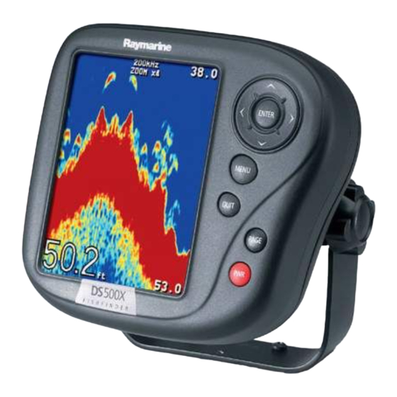
Fishfinder Page, is displayed. This is a graphical representation of the echoes seen by the DS400/500. As time passes, this display scrolls from right to left and becomes a record of the echoes seen. A typical display is shown in Figure 3-2 . - Page 39 Chapter 3: Getting Started Frequency Water surface Depth markers Target image (fish arch) Image depth Bottom depth Range D6637-1 Figure 3-2: Typical Fishfinder Display Screen bereitgestellt von Busse-Yachtshop.de...
-
Page 40: Keypad Operation
DS400 and DS500 Digital Fishfinders 3.5 Keypad Operation The DS400/500 has six keys with which you can control fishfinder operation. ENTER Selects highlighted menu item; Places VRM TRACKPAD Navigates through menu options and changes their value; Moves VRM MENU Displays menu items... -
Page 41: Selecting The Display Page
Press to turn on the fishfinder. Press and hold for three seconds to turn unit off. Press and release as a shortcut to the DISPLAY SET UP... menu. 3.6 Selecting the Display Page The DS400 and DS500 Fishfinders provide you with three Display Pages for presenting information. • Fishfinder Page Displays sounder data. - Page 42 DS400 and DS500 Digital Fishfinders Press to display Temp Screen Press to return to Fishfinder Screen Position Temperature 71.5°F 26°15:512 W 080°04:664 Waypoint 26°16:322 048° W 080°03:846 Press WPT BRG WPT RNG 042° 00 :16 1 . 25 Minutes Time...
-
Page 43: Main Menu
Chapter 3: Getting Started 3.7 Main Menu DS400/500 Fishfinder Page functions can be accessed using the controls that are displayed when you press the MENU key. The Main Menu is displayed. These function control: • General Fishfinder Operations • Display Control Functions •... -
Page 44: Selecting Menu Items
DS400 and DS500 Digital Fishfinders Selecting MENU Items This section provides an example of how to browse through the Main Menu by demonstrating how to make a change to the Gain setting. ➤ To make changes to the menu settings: 1. - Page 45 Chapter 3: Getting Started GAIN MODE GAIN MODE GAIN... AUTO FISHING AUTOMATIC COLOR GAIN... AUTOMATIC Sounder Int Rej AUTO FISHING ENTER Second Echo Rej. Power AUTOMATIC Max. Ping Rate D6644-1 4. To edit the highlighted menu item, press the trackpad < or > keys to scroll through the available options.
- Page 46 DS400 and DS500 Digital Fishfinders GAIN MODE GAIN MODE GAIN MODE GAIN MODE GAIN... MANUAL 75% GAIN... MANUAL 75% ENTER AUTOMATIC AUTOMATIC COLOR GAIN... COLOR GAIN... AUTOMATIC AUTOMATIC Sounder Int Rej AUTO FISHING Sounder Int Rej AUTO FISHING Second Echo Rej.
-
Page 47: Interpreting And Adjusting The Sounder Image
3.8 Interpreting and Adjusting the Sounder Image The DS400/500 uses sound waves to find fish and show the bottom of a lake or sea. The transducer sends high-frequency sound waves into the water; these sound waves strike fish, the bottom, or other objects in the water and return as echoes. -
Page 48: Fish Indications
DS400 and DS500 Digital Fishfinders Fish Indications When the sounder detects a fish, it displays an arch-shaped mark. In general, a larger arch indicates a larger fish, though this rule is not always true. Let’s say that there are two fish of the same size: one is close to the surface, the other is near the bottom. -
Page 49: Using The Variable Range Marker (Vrm)
Chapter 3: Getting Started The shape of the arch is also affected by the speed of the boat. If the boat is moving slowly, the arches tend to be longer; if the boat is moving more quickly, the arches are short and peaked. If the boat is moving very fast, a fish may be indicated by vertical lines. - Page 50 DS400 and DS500 Digital Fishfinders Distance < 75ft > from boat < 75ft > < 75ft > D6640-1 Figure 3-7: Using VRM bereitgestellt von Busse-Yachtshop.de...
-
Page 51: Chapter 4: Menu Operation
Chapter 4: Menu Operation Chapter 4: Menu Operation 4.1 Introduction This chapter provides basic menu functions for using the DS400/500 Digital Fishfinder. More detailed information on using the Display controls and sounder setup is provided in Chapter 5 and Chapter 6, respectively. -
Page 52: Fishfinder Operation Controls
DS400 and DS500 Digital Fishfinders 4.2 Fishfinder Operation Controls The fishfinder operation menu items are outlined in Table 4-1 . Table 4-1: Fishfinder Menu Items Menu Sub-Menu Options Default Scroll Speed — PAUSED Range — AUTOMATIC, AUTOMATIC MANUAL Frequency —... -
Page 53: Scroll Speed
Chapter 4: Menu Operation Menu Sub-Menu Options Default ZOOM... View OFF, SPLIT, FULL SCREEN Zoom X Mode AUTOMATIC, AUTOMATIC MANUAL TRIP RESET... — QUIT = no — ENTER = yes Chapter 5 DISPLAY SET UP... (See Chapter 6 SOUNDER SET UP... (See Scroll Speed This menu item enables you to start and stop the bottom graph display from moving across the screen. - Page 54 DS400 and DS500 Digital Fishfinders The range mode must be set to MANUAL before the range will change. Press UP, DOWN, or MENU. Pressing on the trackpad or pressing the MENU key opens the Range field in the MAIN MENU so you can make the change if desired. If you wish to remain in Automatic Range mode, press QUIT.
-
Page 55: Hunt Mode
200 kHz – 500ft (150m) 50 kHz – 2000 ft (600m) For example, let’s say a DS400/500 is set for auto range & auto frequency and bottom is currently detected at 250 ft using 200 kHz. The bottom signal becomes lost, so the sounder switches to Hunt mode. -
Page 56: A-Scope
DS400 and DS500 Digital Fishfinders • AUTOMATIC enables the digital fishfinder to determine the optimum fre- quency based on the current conditions. 200 kHz MAN fixes the frequency at 200kHz no matter what depth you are • viewing. This frequency is typically used for shallower water and a more detailed view. -
Page 57: Gain Mode
Note: Automatic Gain settings take advantage of the hardware’s advanced digital technology. As a result, the sounder typically performs better in auto- matic mode than manual. For better performance Raymarine recommends selecting AUTO mode for all Gain options. Note that this menu item is in all caps and in followed by an ellipsis (...). This is an indicator that the setting contains sub-menus. -
Page 58: Gain
The DS400/500 provides three pre-defined automatic gain settings: AUTO FISHING is the highest automatic gain setting. It gives the best •... -
Page 59: Color Gain
Increasing the TVG value increases the maximum depth to which TVG is applied. Decreasing reduces the maximum depth. Although you can manually set the TVG level, Raymarine recommends letting the unit choose the proper level for you by selecting AUTOMATIC. -
Page 60: Second Echo Rejection
DS400 and DS500 Digital Fishfinders • LOW minimizes rejection of potential interference. Use this setting when you want to be sure that what has been removed are really false returns. HIGH rejects much more interference but can potentially weaken the •... -
Page 61: Zoom
Chapter 4: Menu Operation ZOOM... Zoom enlarges all or part of the scrolling bottom display at x2, x3 or x4 magnification. You can select automatic zoom so the sounder keeps the bottom in the lower portion of the zoom window or manually pick the area to be zoomed. -
Page 62: Zoom X2, X3, X4 Magnification
DS400 and DS500 Digital Fishfinders ZOOM... ZOOM... View SPLIT Zoom X 2 3 4 Mode AUTOMATIC D6641-1 Figure 4-3: Zoom with Split Screen Zoom x2, x3, x4 Magnification This parameter sets the level of display magnification. The greater the zoom, the smaller the area you are viewing, so the smaller the Zoom Range Bar. -
Page 63: Trip Reset
Chapter 4: Menu Operation TRIP RESET... This option resets the trip log. Once TRIP RESET is selected you have the option to press: QUIT to exit without resetting • ENTER to confirm the reset. • DISPLAY SET UP... These settings determine how information is displayed on the screen. Options are described in Chapter 5. - Page 64 DS400 and DS500 Digital Fishfinders bereitgestellt von Busse-Yachtshop.de...
-
Page 65: Chapter 5: Display Controls
Chapter 5: Display Controls Chapter 5: Display Controls 5.1 Introduction This chapter will help you to become familiar with the functions of the display’s controls. A general discussion of the fishfinder’s menu items was provided in Chapter 4. Information on setting up the sounder is provided in Chapter 6. - Page 66 DS400 and DS500 Digital Fishfinders MAIN MENU MAIN MENU Scroll Speed Range AUTOMATIC Frequency AUTOMATIC MENU A-Scope GAIN MODE... AUTO FISHING ZOOM... TRIP RESET... DISPLAY SET UP... SOUNDER SET UP... MAIN MENU MAIN MENU Scroll Speed Range AUTOMATIC Frequency AUTOMATIC A-Scope GAIN MODE...
- Page 67 Chapter 5: Display Controls The Display Set Up menu items are listed in Table 5-1 and then described following that. Table 5-1: DISPLAY SET UP... Menu Menu Sub Menu Options Default Brightness — 10–100% 100% (Note: never pow- in 10% increments ers up at less than 40%) Target Depth ID —...
-
Page 68: Brightness
DS400 and DS500 Digital Fishfinders Menu Sub Menu Options Default OFF, Bearing Mode TRUE, TRUE MAGNETIC Time Offset UTC, –13 to +13 hours Time Format 12 HOUR, 12 HOUR 24 HOUR Time OFF, ALARM CLOCK OFF, Date Format MM/DD/YY, MM/DD/YY... -
Page 69: Depth Digit Size
• PALETTE... The DS400/500 offers you six different display color combinations. You can select the color set, for a bold or soft color palette. The brightness of the screen can be adjusted over a wide range, suitable for viewing in daylight (high brightness level) or at night (low brightness level). -
Page 70: Data Items
DS400 and DS500 Digital Fishfinders Select from the following: WHITE (default) • BLACK • BLUE • DATA ITEMS... Data Items provide regularly-used data in a compact form so that most of the graphics can still be seen. Each data item can be displayed in a separate data field or scrolled through a single data field every three seconds. -
Page 71: Nav. Set Up
Chapter 5: Display Controls NAV. SET UP... (Navigation Data) Similar to Data Items, this is a list of navigation data you can display on the screen as separate data items. Select from the following: • Speed Over Ground Display ON or OFF LAT/LONG •... - Page 72 DS400 and DS500 Digital Fishfinders Note: When analog gauges are selected as Data Items, the Navigation Items cannot be displayed on the Fishfinder page; you need to switch to the Nav Data page using the PAGE key to view this information.
-
Page 73: Chapter 6: Sounder Setup
Chapter 6: Sounder Setup 6.1 Introduction Once you have installed your DS400/500 and are familiar with its basic operation, you need to set it up so that it displays information according to your preferences. The SYSTEM SET UP option enables you to set up your system configuration and personal preferences. - Page 74 DS400 and DS500 Digital Fishfinders MAIN MENU MAIN MENU Scroll Speed Range AUTOMATIC Frequency AUTOMATIC MENU A-Scope GAIN MODE... AUTO FISHING ZOOM... TRIP RESET... DISPLAY SET UP... SOUNDER SET UP... MAIN MENU MAIN MENU Scroll Speed Range AUTOMATIC Frequency AUTOMATIC A-Scope GAIN MODE...
- Page 75 Chapter 6: Sounder Setup The following table lists the setup menus and their options and shows the factory default setting. Each parameter is described in the following subsections. Table 6-1: SOUNDER SET UP... Menu Items Menu Sub-Menu Options Default ALARMS... Target Depth ID OFF, DEPTH,...
- Page 76 DS400 and DS500 Digital Fishfinders Menu Sub-Menu Options Default Speed Units KNOTS, KNOTS MILES PER HOUR, KM PER HOUR Distance Units NAUTICAL MILES, NAUTICAL MILES STATUTE MILES, KILO METERS KILO YARDS Bearing Mode TRUE, TRUE MAGNETIC Date Format MM/DD/YY, MM/DD/YY...
-
Page 77: Alarms
Chapter 6: Sounder Setup Menu Sub-Menu Options Default Depth Offset — –9.9 to +9.9 FEET, –1.7 to +1.7 FATHOMS, –3.0 to +3.0 METERS Speed Calibrate — 1% to 200% in 1% incre- 100% ments Temp Calibrate — –5.0 to +5.0°C 0°... -
Page 78: Target Depth Id
DS400 and DS500 Digital Fishfinders Note: After you have acknowledged the sounding of a shallow or deep water alarm, a minimum of 30 seconds must elapse before a another shallow/deep alarm can sound again. However, the visual indicator will continue as long as the condition exists. -
Page 79: Deep Range
Chapter 6: Sounder Setup Deep Range Use the < and > trackpad keys to decrement/increment the depth at which the Deep Alarm will sound. The depth units are dependent on the value set using the UNITS... parameter. (See page 71.) Changing the value set for Deep Range automatically enables the Deep Alarm. -
Page 80: Alarm Clock
DS400 and DS500 Digital Fishfinders ALARM CLOCK... Set this alarm to sound the beeper at a particular time of day. ➤ To enable the Alarm Clock: 1. Select (highlight) ALARM CLOCK. 2. Press the < or > trackpad key to change the setting from OFF to ON. -
Page 81: Units
Chapter 6: Sounder Setup UNITS... You can set the units for each system parameter. The units you set will be used to display all data, including information received from other instruments on the system. Depth Units FEET (default) • FATHOMS •... -
Page 82: Time Format
DS400 and DS500 Digital Fishfinders Time Format 12 HOUR (default) • 24 HOUR • NMEA-OUT SET UP... This option lets you disable the transmission of specific NMEA sentences, which may be necessary if you have other instruments sending the same data as your sounder. -
Page 83: Language
Chapter 6: Sounder Setup Language Select the language in which you wish information to be displayed. The selected language will be used for all screen text. Select from the following: ENGLISH (UK) • ENGLISH (US) (default) • DANISH • FRENCH •... -
Page 84: Speed Calibrate
Log, Trip and paddlewheel distance. Temp Calibrate If the transducer is equipped with a thermistor, the DS400/500 calculates the temperature of the water. The temperature calibrate option enables you to adjust the displayed temperature.in 0.1 degree increments of the temperature units you have assigned using the UNITS... -
Page 85: Chapter 7: Maintenance And Problem Solving
Check that the cable connectors are firmly attached. Cleaning Instructions Cleaning the Unit The DS400/500 is a sealed unit and does not require regular cleaning. However, if you find it necessary to clean the unit, please follow these basic procedures: •... -
Page 86: Emc Servicing And Safety Guidelines
To minimize these effects and enable you to get the best possible perfor- mance from your Raymarine equipment, guidelines are given in the installation instructions, to enable you to ensure minimum interaction between different items of equipment, i.e. -
Page 87: Problem Solving
Chapter 7: Maintenance and Problem Solving 7.2 Problem Solving All Raymarine products are, prior to packing and shipping, subjected to comprehensive test and quality assurance programs. However, if this unit should develop a fault, please refer to the following table to identify the most likely cause and the corrective action required to restore normal operation. -
Page 88: How To Contact Raymarine
Clicking the Find Answers link routes you to our solution database. Search questions and answers by product, category, keywords, or phrases. If the answer you are seeking is not available, click the Ask Raymarine tab to submit your own question to our technical support staff, who will reply to you by e-mail. -
Page 89: Technical Support
Technical Service is available Monday through Friday 4:00 AM to 6:00 PM Eastern Time. Please have the Raymarine item or part number ready when calling if placing an order. If you are not sure which item is appropriate for your unit, you... -
Page 90: In Europe
Accessories and Parts Raymarine accessory items and parts are available through your authorized Raymarine dealer. Please refer to the lists of component part numbers and optional accessories in the Installation chapter of this manual and have the Raymarine part number ready when speaking with your dealer. -
Page 91: Appendix A:specifications
DS400 4.45 x 5.12 x 2.7 in (113 x 130 x 68.6 mm) DS500 5.90 x 6.37 x 3.08 in (150 x 162 x 78.3 mm) 1 lb (448 g) Weight DS400 1.53 lbs (692g) DS500 Environmental Waterproofing: Submersible to IPX7 standard;... -
Page 92: Nmea Data
DS400 and DS500 Fishfinders NMEA Data Connector Received Transmitted POWER/NMEA BWC, BWR, GLL, ZDA, BWC, BWR, DBT, DPT, RMB, VTG, HDG, HDT GLL, MTW, VHW, VLW, VTG, ZDA bereitgestellt von Busse-Yachtshop.de... -
Page 93: Index
Index Log 60 Speed 60 Temperature 60 Trip 60 Date Format 61 Accessories 6 Date Setting 61 Obtaining 78 Deep Alarm 68 Alarm Clock 61 Deep Range 69 Alarms 67 Depth Digit Size 59 Alarm Clock 70 Depth Offset 73 Deep Alarm 68 Depth Units 71 Deep Range 69... - Page 94 DS400 and DS500 Digital Fishfinders List Display Set Up Menu items 57 Echoes 28 Main Menu items 42 Strength 37 Sounder Set Up Menu items 65 ENTER key 30 Location Mounting 7 Features 2 Log 60 Fish Alarm 68 Fish Indications 38...
- Page 95 QUIT key 31 Key Beep 73 Key Help 73 Range 43 Language 73 Range and Bearing 61 Menu List 65 Raymarine NMEA-out Set Up 72 Addresses 79 Serial Number 74 Phone numbers 79 Sounder Simulator 74 Website 78 Speed Calibrate 74...
- Page 96 DS400 and DS500 Digital Fishfinders Speed 60 Website 78 Speed Calibrate 74 Speed Units 71 Zoom 30 System Magnification 52 Connections 13 Mode 52 View 51 Target Depth ID 58 Technical Support 79 Temp Alarm 69 Temp Calibrate 74 Temp Graph Page 31...