Advertisement
Quick Links
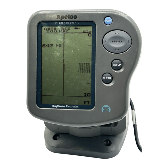
The FishFinder 365 is a system that uses sound waves ("sonar") to detect
fish and show the bottom of a lake or sea. The system includes a trans-
ducer and a display unit, connected by a cable. The transducer sends
high-frequency sound waves down into the water. These sounds strike
fish, the bottom, or other objects in the water, and return as echoes. The
FishFinder then interprets these echoes and presents a display.
The FishFinder 365 can handle many different jobs:
•
detect the presence of fish below the boat
•
trigger an alarm when fish are found
•
measure the depth of the water
•
set alarms for minimum and maximum depth
•
show the shape of the bottom
•
determine whether the seabed is hard or soft
•
measure the speed of the boat and the distance traveled
•
show the water temperature
We are sure you will find the FishFinder 365 to be one of the most useful
devices on your boat.
Optional Thru Hull
Transducer
Transducer mounted
in quick release
transom bracket
Apelco
FishFinder 265
Display Unit
PWR
PAGE
SETUP
CLEAR
265
Typical Installation
1
Advertisement

Related Manuals for Raymarine 365


Summary of Contents for Raymarine 365
- Page 1 • measure the speed of the boat and the distance traveled • show the water temperature We are sure you will find the FishFinder 365 to be one of the most useful devices on your boat. Apelco FishFinder 265 PAGE...
- Page 2 Instruction manual G623958-1 Four #10 x 3/4” ss mounting screws — Depending on which model of the 365 you have purchased, the box will include one of the transducers listed below: Transom-mount transducer (with speed and temperature sensors, including mounting bracket and hardware)
- Page 3 M78922, M78928, M78946) M78936 Replacement transom transducer mounting bracket kit M99-148 Soft storage/carrying case M99-114 Transducer switch box (select between two 365 FishFinder displays, using one transducer) M99-136 Replacement paddle wheel kit (for transom- mount transducer) M99-143 Replacement paddle wheel kit...
- Page 4 The installation process has four parts: • Mounting the transducer • Mounting the display unit • Connecting the cables for the transducer and power supply • Calibrating the display unit Several different kinds of transducers can be used with this unit. The transom-mount type is used most often.
- Page 5 Transom-mount Thru-hull Fairing for transducer transducer thru-hull transducer Low profile In-hull Sidelooker Transducer transducer transducer transducer Types Before you begin the installation, double-check to be sure you have the correct type of transducer. Each kind of transducer is designed for a particular type of use.
- Page 6 Use a trolling motor transducer if – . . . you want to attach the transducer to a trolling motor. Use a Sidelooker transducer if – . . . you need a way of searching for fish on either side of the boat. This type of transducer is attached to the bracket of the transom-mount transducer.
- Page 7 Transducer Mounted on Transom Allow a clearance Transducer in of at least 10 released position inches (254 mm) 10" (254 mm) Transducer Bracket, Side View mm) beyond the swing radius of the propeller. This will prevent the propeller from damaging the transducer when it is turned. Do not mount the transducer behind any hull fittings, intakes, or other •...
- Page 8 Average transom angle– Vertical transom – Sloping transom– no wedge necessary place wedge this way place wedge this way 2° to 5° 2° to 5° 2° to 5° For fiberglass hull – 1/8" to 1/4" (3.2 to 6 mm) For aluminum hull – 1/4" to 3/8" (6 to 9 mm) The bow of the transducer Rivets on the hull are The rear of the transducer...
- Page 9 can swing upward completely. This is about 10" (254 mm) measured from the bottom of the transom. • If the boat will be carried on a trailer, be sure the transducer will not hit any rollers, bunks or fittings on the trailer. On a boat with a fiberglass hull, the leading edge of the transducer should extend 1/8"...
- Page 10 Once the bracket is in the correct position, you can tighten the screws. The Sidelooker transducer allows the display unit to check the water to either side of the boat. This is helpful when you are looking for fish near river banks, or under docks or piers. The Sidelooker transducer is attached to the same mounting bracket used with the transom-mount transducer.
- Page 11 Earlier we listed three general rules for placing transducers. All of these rules apply when you are mounting a thru-hull transducer. Here are some other rules for selecting the best mounting location: For planing hulls – Install in the flat planing area near the stern. Always install forward of the propeller(s) and shaft(s).
- Page 12 When working with the transducer, support it by holding the body of the unit or the rings. Do not hang the transducer from the cable. It is very important to seal the opening around the transducer using a high-quality marine sealant suitable for underwater use. After installation, do not leave your boat in the water for any amount of time without checking for leaks.
- Page 13 This type of transducer may be used with a thru-hull transducer which reads depth only. The speed/temperature transducer is attached to the transom of the boat. Detailed instructions for this installation will be included with the transducer. The cable for this transducer uses a “Y” connector.
- Page 14 Countersink 2-25/32" 3/8" (10 mm) (70 mm) Hole 3/16" (5 mm) 2-21/32" (67 mm) 2-23/32" (69 mm) 1-13/32" (36 mm) 5-7/32" (133 mm) 63/64" (25 mm) 6-3/4" (172 mm) 5-9/32" (134 mm) 1-3/4" (44 mm) 4-9/32" (109 mm) 3-29/32"(99 mm) 4-7/32"(107 mm) Dimensions...
- Page 15 Mount the base of the bracket using the supplied screws. Slide the display unit back into the bracket. Adjust the display unit for the best viewing angle. You can turn the display from side to side, and tilt it up or down. In order to do this installation, you will need the optional flush mounting kit (part no.
- Page 16 Separate the display unit from the mounting bracket. (See Fig. 2-11.) Press the large button in the center of the bracket to separate the bracket arms. The display unit is attached to the arms by two screws. Each screw is covered by a cap. Locate the small slot beside each cap and pry upward using a small screwdriver.
- Page 17 transducer. During the installation, do not cut the transducer cable or remove the connector. Do not try to shorten or splice the cable. The transducer cable includes several wires, along with shielding and insulation. If the cable is cut, it cannot be repaired. (Cutting the cable will also void the warranty.) During installation, if you need to drill any holes for the cable, they must be large enough to accept the connector.
- Page 18 away from the FishFinder power cable. If it is necessary to run the transducer cable across any wires, make the crossing at a right angle. Be careful not to tear the cable jacket when passing it through bulkheads and other parts of your boat. Secure the cables in place using tywraps or lacing twine.
- Page 19 Plug the cable from the depth-only transducer into the receptacle connector on the optional speed- and temperature-only transducer. The speed- and temperature-only transducer then connects at the transducer receptacle of the FishFinder 365. This is shown below in Fig. 2-14. Sensor for...
- Page 20 use on boats with positive ground. The 6-foot power cable supplied with the display unit should reach the source of DC power. On a small boat, connect the power leads directly to the main battery isolation switch or breaker. On a larger boat, route the power leads to the DC power distribution panel.
- Page 21 larger wire size. This will allow the wires to deliver the correct voltage in spite of the longer wire distance. For runs of 20 to 35 feet, use #14 AWG. If you extend the power wiring, be sure all electrical connections are solid and durable.
- Page 22 over ground” or “speed over the bottom.” Tides, currents, or winds can create a difference between the FishFinder’s “speed through water” measurement and the boat’s “speed over ground.” Before calibrating using a G.P.S. or Loran unit, wait for still water or slack tide conditions.
- Page 23 In this section of the manual, we will explain how to operate the unit. (Setup instructions are included in the next section.) Below is a drawing of the display unit. Power button Display area Page control PAGE Set-up button SETUP Clear button CLEAR Display...
- Page 24 the display will say “Powering Off.” If you hold the button for more than 3 seconds, the display unit will switch off. Page control Up and down arrows – ( During setup – Use these controls to call up a choice or move to the next line on a menu.
- Page 25 This unit has a memory for some of the settings – range, sensitivity, zoom, and frequency. (We will explain these in a moment.) When you turn off the power, any changes you make to these settings will be saved. You can return all of the settings to the factory default values, and reset the trip log to zero.
- Page 26 Selecting Display Lamp/Contrast menu FishFinder page Pages A-Scope page Zoom page Sidelooker page Digital page Note: This will appear only if the Sidelooker feature is turned on. Return to FishFinder page...
- Page 27 Adjust contrast You can also adjust the “contrast” of the display. This is a measure of how light or dark the display appears. Use control to move from the line for “Lamp On/Off” to the line for “Contrast.” Use the < or > controls to adjust the contrast.
- Page 28 Auto Auto sensitivity on zoom on Auto range on Auto Fish symbol features on Transducer Boat symbol frequency Water surface Speed Log/distance Water temperature Depth markers Fish depth Bottom indication Fish symbol Range Buzzer symbol Bottom depth Fish alarm set Deep alarm set Shallow alarm set FishFinder...
- Page 29 Some of these echoes indicate fish, and others show the bottom. As new echoes are received, the FishFinder “draws” a graph of the bottom. The bottom graph helps you to tell whether the bottom is rising or falling. It also allows you to identify the shape or “structure” of the bottom. This can indicate a reef or shipwreck.
- Page 30 Auto zoom on (Z) The “zoom” can be used to magnify the image from a small section of the water below the boat. (This is used with the Zoom display, which we will describe in a moment.) When the auto zoom feature is on, the FishFinder automatically moves the zoom window up or down to track the bottom.
- Page 31 Water temperature This entry shows the current water temperature at the surface of the water. (The reading for water temperature can be helpful for finding fish. A particular type of fish will often prefer water in a narrow temperature range.) From the System Setup display, you can turn this item off or change the units used for this display.
- Page 32 This will continue until the unit can see the bottom again. Buzzer symbol This symbol shows whether any of the alarms will use the buzzer. There are three kinds of alarms: shallow, deep, and fish. If one of these alarms is set, it will always present a flashing symbol on the display.
- Page 33 Before we explain the other pages, there are some general things you should know about the operation of the FishFinder. We said that the FishFinder uses sound waves to “see” through the water under the boat. The “frequency” is a measure of how fast the sound waves change or “vibrate.”...
- Page 34 There is really nothing very solid for the sound waves to bounce off of. The FishFinder 365 is very good at telling the difference between a fish and the surrounding water. In fact, Apelco is the leader in this technology.
- Page 35 An arch-shaped image indicates a fish. The same fish appears differently when shown by the 50 kHz or 200 kHz 50 kHz transducer beams. 200 kHz This indicates a group of small fish. This shows a fish detected in sidelooker mode. A shallow arch or horizontal line is generated when the boat is moving slowly or stopped.
- Page 36 Hard (Sand) Soft Rocks (Mud) Bottom Conditions Notice that the lower layer of the bottom is shown as a solid display. This indicates a weaker echo. Sometimes this means that the upper layer of the bottom is soft. Some of the sound waves may reach through this layer, and may be reflected by a more solid layer below.
- Page 37 Zoom display Normal (magnified) display Top of zoom area Line indicates zoom area Bottom of zoom area Zoom magnification Zoom Page The Zoom page gives you a way of enlarging or magnifying a part of the display area. See Fig. 3-7. (The “zoomed” display is actually larger only in the vertical direction.) The right side of the display shows the same information as the FishFinder page.
- Page 38 Zoom magnification This indicates the amount of “zoom” or magnification. You always set the amount of zoom manually, using one of the functions on the Setup display. You can choose an x2 view (double the normal display size), x4, x6 or x8 in the series of setup screens.
- Page 39 Normal A-Scope display display A-Scope image (real time image) Fish indication Bottom coverage A-Scope Mode Display On the FishFinder display the bottom graph is “drawn” after the FishFinder receives several echoes. This has the effect of showing a record of the bottom contour.
- Page 40 A-Scope image This shows the beam of sound waves extending down from the boat, and spreading as it moves through the water. Any fish or objects which are positioned under the boat will appear on the display. This is a “real time” display, so you can see the fish symbols moving as the fish swim under the boat.
- Page 41 This is the speed of the boat through the water. This entry shows the distance traveled, determined by the speed through the water. The 365 remembers this value after it is turned off. You may reset the log using the Setup Menu.
- Page 42 The Sidelooker feature is very helpful for certain kinds of fishing. It allows you to check along the sides of a stream or river. You can also look under the edge of a bank or pier, or into a snag or shallow spot. The Sidelooker page, like the FishFinder page, displays a graph or chart.
- Page 43 Boat symbol Side range Fish echo Rock Centerline Speed Log/distance Water temperature Depth below boat Sidelooker Display the display moves is set by the entry for “chart speed” in the Setup Menu.) New information appears at the top of the display. The Sidelooker transducer transmits at the 200kHz frequency.
- Page 44 noise or clutter when your boat travels at high speeds. For best results, use the Sidelooker at idle or slow trolling speeds. Here are the special items on this display: Boat symbol This shows that the bow of the boat is aiming forward, toward the top of the display.
- Page 45 Press the Setup button to enter the Setup Menu. To move from one display to another, press the arrows of the Page control pad. To return to the normal display, press . See Fig. 4-1. This means that you can reach these displays quickly, make a change, then return to the normal display quickly.
- Page 46 Range Settings If you press once, the first menu item allows you to set the range. SETUP See Fig. 4-2. The range sets the maximum depth the unit will be able to see. Use the < and > arrows of the Page control pad to select Auto or Manual range.
- Page 47 Sensitivity Setting This adjusts the ability of the unit to tell the differences between echoes of different strengths. In general, the sensitivity should be as high as possible, to detect the fish and show the detail on the bottom. However, if the sensitivity is too high, the unit will begin to see bubbles in the water, debris, and other “background noise.”...
- Page 48 background noise changes, the FishFinder will not adjust for this. If you choose Manual sensitivity, press the arrow of the Page control pad to go to the next line. Use the < and > arrows of the Page control pad to move the dark bar on the display.
- Page 49 A faster chart speed setting shows more detail on the bottom. You will probably want to use a faster setting when you are looking for fish. A slower chart speed setting shows a longer record of the bottom you pass over. Any fish detected will stay on the display longer. From the display for the sensitivity setting, press the arrow of the Page control pad.
- Page 50 Zoom Settings The “Zoom” feature allows you to enlarge or magnify a section of the normal display. This lets you see a “window” of the echosounder view in detail. The Zoom window may be set for four different levels of magnifica- tion.
- Page 51 display, and you are looking at the Zoom display itself. You can manually move the Zoom area up or down by pressing arrows of the Page control page. The location of the zoom area is shown by the dark vertical line at the very right-hand edge of the display.
- Page 52 narrow 200 kHz beam. • 50 kHz dual frequency – The unit will use both frequencies, but the image on the display will be generated using the information from the wider 50 kHz beam. If you are using one of the dual frequency choices, some of the fish may be revealed by one beam, but not the other.
- Page 53 Reaching the System Setup Display You can reach the System Setup display at any time by pressing the Setup button twice. This means that you can reach this display, make a change, then return to the normal display quickly. See Fig. 4-9. Figure 4-10 shows the items in this display.
- Page 54 To change one of the items, use the arrows of the Page control pad to move up or down in the display. This will highlight an area on the display where the unit is ready to make a change. (This is like the “cursor” on a computer.) Once you have moved to the correct line, press the <...
- Page 55 transducer, use this line of the display to turn on the Sidelooker mode. Speed Cal This unit can detect and display the speed of the boat through the water. It also uses the speed information to calculate the distance traveled (the “log”). The item for Speed Cal allows you to adjust the speed reading to make it match your actual speed through the water.
- Page 56 When the shallow alarm is set, the letter “S” will appear in the lower left-hand corner of the normal displays. If you move into shallow water and trigger the alarm, the letter “S” will begin to flash, and the buzzer will sound. Press the button to silence the buzzer.
- Page 57 silence the buzzer for the current alarm condition . The “S” or “D” symbol will continue to flash as long as the alarm condition is still present. If the alarm condition occurs again, the buzzer will sound again. (For example, this would happen if, after a shallow alarm you move into deep water, then return to shallow water.) You can silence the buzzer again by pressing the button.
- Page 58 You can choose Fahrenheit degrees (°F) or Celsius degrees (°C). Use the < and > controls to make your choice. Speed A speed indication appears on all of the normal displays. If you do not want to see this item, you can turn it off using this line of the System Setup display.
- Page 59 Next, press the > arrow of the Page control pad until you see the Sidelooker page. The next job is to set up the range, sensitivity, and chart speed for the Sidelooker feature. While the unit is displaying the Sidelooker page, press button once.
- Page 60 Sidelooker Sensitivity Settings This menu item allows you to set the sensitivity for the Sidelooker feature only. (This will not change the sensitivity setting for the other display pages.) Choose Auto or Manual sensitivity. If you choose Manual sensitivity, use the < and > arrows of the Page control pad to adjust the sensitivity.
- Page 61 When the FishFinder is new, it uses a number of preset “default” settings. Here is a list: Range Auto Auto Sensitivity Auto Auto Chart Speed 3 (fast) 3 (fast) Zoom Auto/x4 Auto/x4 Frequency Dual 200 kHz Dual 200 kHz Simulator Fish symbols White line Sidelooker...
- Page 62 Periodically check the display unit, cable, and transducer. Be sure all components are free of corrosion and are securely mounted. Check all cables for signs of chafing or abrasion. Be sure all of the connections to the boat’s DC power and ground system are clean and tight. Always keep the display unit clean.
- Page 63 the factory defaults. See the default settings on page 61. If the power wiring includes a fuse, it may be blown. Also check the circuit breaker or main battery switch. You may have reversed the power connections. Follow the DC power lines all the way back to the battery.
- Page 64 The transducer cable may be damaged. Check for any point where the wiring may be pinched or bent. Look for signs that water has gotten into the cable. If the transducer cable is damaged, the transducer and cable should be replaced as a unit. Contact Apelco for instructions.
- Page 65 the System Setup display. The FishFinder will not display arches unless the boat is moving. If the boat is stopped, fish will appear on the display as straight lines. The transducer may not be aimed straight down. In order to display complete arches, the transducer must be vertical.
- Page 66 Apelco unit. You may also reach our Technical Support Department via the Internet. Questions may be addressed directly to: rmc_tech_apelco@raymarine.com Or, you may visit Apelco at the World Wide Web site for Raytheon Electronics: www.raymarine.com...
- Page 67 For accessories and parts Please call 1-800-539-5539, extension 2120 or (603) 647-7530 extension 2120. Our Customer Service Department is available Monday through Friday, 8:15 . to 5:00 . Eastern Time. Please have the Apelco part number ready when calling to place an order. (See the Optional Accessory List in this manual on page 3.) If you are not sure which item you need for your Apelco unit, please contact our Technical Support Department before placing your order.
- Page 68 Prepaid U.P.S. return service The U.P.S. return label included with your Apelco unit provides free U.P.S. ground shipping to our Product Repair Center for all warranty repairs. See Fig. 5-1. (This service is available only to customers within the continental United States.) To return your Apelco unit for warranty repair, please follow these steps: Fill out the service information card completely.
- Page 69 Display panel FSTN high-contrast LCD Panel dimensions 3.6" H (61 mm) x 2.4" W (91 mm) No. of dots 240 x 64 LCD contrast Adjustable, with temperature compensation Backlight LCD panel, on/off Operating modes FishFinder mode (standard mode) Zoom mode A-Scope mode Digital mode Sidelooker mode...
- Page 70 Range Auto or manual FT (feet) 1000 1500 2000 FA (fathoms) M (meters) Zoom size x2, x4, x6, x8 Chart speed Freeze, slow, medium, fast White line On/ Off Alarms Shallow, deep, fish Reset distance log 0 to 999 units Fish symbols 5 sizes Output power...
- Page 71 DC power connector Pin 1 Ground (-) Pin 2 12V DC (+) (Connectors viewed looking toward rear of display unit.) Transducer connector Pin 1 Depth TX+ Pin 2 Depth TX- Pin 3 L Select Pin 4 Temp Pin 5 R Select Pin 6 Speed signal/voltage + Pin 7...
- Page 72 Aft: Near or toward the rear part of the boat (nautical term). Background noise: False or meaningless echo returns produced by bubbles, water turbulence, or debris Bow: The front of the boat (nautical term). Cavitation: Air bubbles in the water which affect the readings of a transducer.
- Page 73 Knot: One nautical mile per hour (1.15 statute miles per hour). LCD: “Liquid Crystal Display” - A technology used to produce flat-panel displays. Nautical mile: 6076 feet Port: Left side of the boat, when facing the bow (nautical term). PVDF: “Poly Vinylidene Fluoride” – A unique polymer plastic that has the ability to convert sound waves into electrical impulses.
-
Page 74: Limited Warranty Certificate
Limited Warranty Certificate Apelco Marine Electronics warrants each new Product to be of sound design, good materials and workmanship, and will repair or exchange any parts proven to be defective in material and work- manship under normal use for a period of 2 years/24 months from date of sale to end user, except as provided below.