
Related Manuals for Planet WGSW-2840


Summary of Contents for Planet WGSW-2840
- Page 1 24/48-Port 10/100Mbps + 4G TP/SFP Combo Managed Ethernet Switch WGSW-2840/WGSW-5240 User's Manual...
-
Page 2: Fcc Warning
Trademarks Copyright © PLANET Technology Corp. 2005. Contents subject to which revision without prior notice. PLANET is a registered trademark of PLANET Technology Corp. All other trademarks belong to their respective owners. Disclaimer PLANET Technology does not warrant that the hardware will work properly in all environments and applications, and makes no warranty and representation, either implied or expressed, with respect to the quality, performance, merchantability, or fitness for a particular purpose. -
Page 3: Table Of Contents
2.1 P ... 8 RODUCT ESCRIPTION 2.1.1 Product Overview... 8 2.1.2 Switch Front Panel... 8 2.1.3 LED Indications... 9 2.1.4 Switch Rear Panel ... 9 2.2 I ... 9 NSTALL THE WITCH 2.2.1 Desktop Installation... 10 2.2.2 Rack Mounting ... 10 3. - Page 4 4.4.8 Load Default... 28 4.4.9 Reboot ... 28 4.5 P ... 29 ANAGEMENT 4.5.1 Port Configuration ... 29 4.5.2 Port Statistics ... 29 4.5.3 Port Band Restrict... 30 4.6 R ... 31 EDUNDANCY 4.6.1 Spanning Tree... 31 4.6.2 Spanning Tree Configuration ... 37 4.6.3 Link Aggregation ...
-
Page 5: Introduction
The chapter explains how to trouble shooting of the Switch. Chapter 6, APPENDIX The chapter contains cable information of the Switch. In the following section, terms "SWITCH" with upper case denotes the WGSW-2840/WGSW-5240 Ethernet switch. Terms with lower case "switch" means any Ethernet switches. 1.3 Product Feature ▫... -
Page 6: Product Specification
Static Routing Port Management Function WGSW-2840 24-Port RJ-45 for 10/100Base-TX 4-Port Gigabit TP/SFP mini-GBIC combo interfaces One RS-232 DB-9 male connector for switch management Store and forward switch architecture. Back-plan up to 12.8/17.6Gbps 8K MAC address table with Auto learning function 4Mbit... - Page 7 Management Interface Console/Web/Telnet/SNMP SNMP Version v1, v2c Support MIB Support SNMP MIBⅡ(RFC 1213), Bridge MIB (RFC 1493), RMON group 1,2,3,9 Enterprise private MIB Standard Compliance Network Standard IEEE802.3 10Base-T IEEE802.3u 100Base-TX IEEE802.3z Gigabit SX/LX IEE802.3ab Gigabit 1000Base-T IEEE802.3x Flow Control and Back pressure IEEE802.3ad Port trunk with LACP IEEE802.1d Spanning tree protocol IEEE802.1w Rapid Spanning Tree...
-
Page 8: Installation
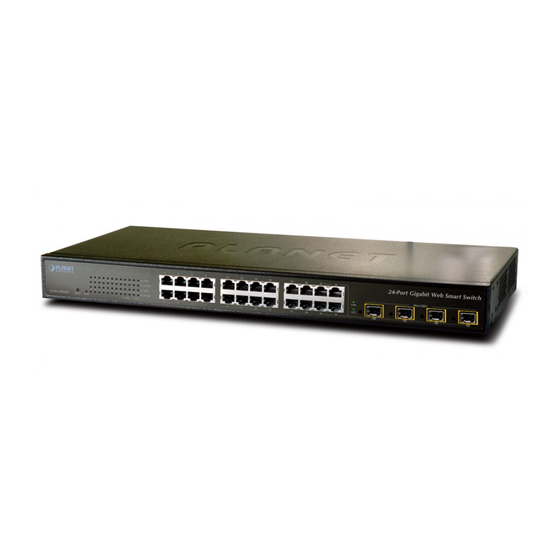
2.1 Product Description 2.1.1 Product Overview The PLANET WGSW-2840/5240 is a 24/48-Port 10/100Mbps fast Ethernet Switch with 4-Port Gigabit TP/SFP Combo interface which boasts a high performance switch architecture that is capable of providing non-blocking switch fabric and wire-speed throughput as high as 12.8/17.6Gbps. Its four built-in GbE uplink ports also offer incredible extensibility, flexibility and connectivity to the Core switch or Servers. -
Page 9: Led Indications
It will prevent you from network data loss or network downtime. In some area, installing a surge suppression device may also help to protect your switch from being damaged by unregulated surge or current to the Switch or the power adapter. -
Page 10: Desktop Installation
To install the switch in a 19-inch standard rack, please follows the instructions described below. Step1: Place the switch on a hard flat surface, with the front panel positioned towards the front side. Step2: Attach the rack-mount bracket to each side of the switch with supplied screws attached to the package. - Page 11 Step4: Follow the same steps to attach the second bracket to the opposite side. Step5: After the brackets are attached to the Switch, use suitable screws to securely attach the brackets to the rack, as shown in Figure 2-6 Figure 2-6 Mounting the Switch in a Rack Step6: Proceeds with the steps 4 and steps 5 of session 2.2.1 Desktop Installation to connect the...
-
Page 12: Console Management
Switch. Use the supplied RS-232 cable with a male DB-9 connector to connect a terminal or PC to the Console port. The Console configuration (out of band) allows you to set Switch for remote terminal as if the console terminal were directly connected to it. -
Page 13: Console Management
type “enable” for further configuration. The system needs password for further configuration. After the “enable” command, the system asks for password, please enter “admin” for the default password. As shows in the following screen: Console login screen 3.3 Console Management Entering a question mark "?"... -
Page 14: Telnet Login
3.4 Telnet login The switch also supports telnet for remote management. The switch asks for user name and password for remote login when using telnet, please use “admin” for username and “admin” for password. 3.5 Commands There are two levels for console commands. The first level provides commands to show system informations and current configurations. -
Page 15: Privileged Command
To access to the second level, enter the “enable” command in the first level. The sysem then prompt for a password. Please enter “password” for the password. The promt then changes to “Switch\enable>”. Entering a question mark "?" at the prompt displays the list of commands available for command mode. -
Page 16: Copy Command
Disable command is to exit the privileged mode and back to the first level of command line interface. Command Disable 3.5.2.4 Reboot command Reboot command is to reboot the switch, please beware to check if the configuration is saved.. Command Reboot Clear static MAC entry... -
Page 17: Set Command
3.5.2.5 Set command Set command is to change the parameter of the switch functions. The follow table lists the set commands and the equivalent usages. Command set channel set default set enable password set igmp-snooping disable set igmp-snooping enable set ip http server disable... -
Page 18: Show Command
3.5.2.6 Show command Show command is to display the current parameter of the switch functions. The follow table lists the show commands and the equivalent usages. Command show channel show console-info... - Page 19 show mirror show multicast router show port counter show port rate-shaping show port spantree show port state show port storm-limit show qos map cos-queue-map show qos map dot1p-cos-map show qos map mac-cos-map show qos map port-cos-map show qos map vlan-cos-map show qos queue egress-policy show security MAC-aging show security filter-MAC...
-
Page 20: Web-Based Management
Java Applets to use network ports. 4.2 Preparing for Web Management Before use web management, you can use console to login the Switch checking the default IP of the Switch. Please refer to Console Management Chapter for console login. If you need change IP address in first time, you can use console mode to modify it. -
Page 21: System
The switch can be managed by the Web/Telnet/SNMP interfaces. Administrators can access the management interface via the IP address of the switch. The default IP address of the switch is 192.168.0.100. You can change the IP address to be in the same IP segment as your LAN network for convinence. -
Page 22: Snmp
2. The changed IP address take effect immediately after click on the OK button, you need to use the new IP address to access the Web interface. 3. The changed IP address remains the original after reboot the switch unless the configuration is saved. To save the changed IP address, please move to System/Saving Parameters menu. -
Page 23: Snmp Configuration
SNMP Management function, as shows in the following: The followings are the description of the sub-table. 1. SNMP Agent Status Configuration This block enables to turn on SNMP Agent. Enabled / Disabled: To turn on or turn off the SNMP function on the Switch. 2. System Options... - Page 24 Use this table to configure the SNMP community strings and define the policy of the relative string. The community string acts like a password to permit access to the agent on the Switch. One or more of the following characteristics can be associated with the community string: Add Community: enter private or public 。...
- Page 25 A trap manager is a management station (SNMP application) that receives traps (the system alerts generated by the switch). If no trap manager is defined, no traps are issued. Create a trap manager by entering the IP address of the station and a community string.
-
Page 26: Password
4.4.3 Password The Password management menu is to set or change the password of the Web Management Interface. Click on System/Password menu button, and the Modify Password table shows in the main web page. Enter “old password “, “new password”, “confirm password” Click “OK” to change the password. 4.4.4 CONSOLE This function shows the connection parameters for the Console Management Interface. -
Page 27: Saving Parameters
It takes effect immediately when you change the parameters of the management function when the switch is running. But the parameters would not be saved after reboot the swith. To keep the changed parameters, Click on the System/Saving Parameters menu button, and click on the “Save” button on the web main page as show in the following. -
Page 28: Load Default
4.4.8 Load Default This function is to reset the configuration of switch to the factory default. Click on the System/Load Default menu button, and the following table shows in the web main page. -
Page 29: Port Management
Config: (configured) Displays the state defined by the user. 。 Atual: Displays the negotiation result. 。 4.5.2 Port Statistics The Port Statistics page provides a view of the current status of every port on the Switch. Pressing the “Reset” button will reset all port counters to zero. -
Page 30: Port Band Restrict
4.5.3 Port Band Restrict The function provides the In-Band and Out-Band connection speed restriction on the ports. The Band of the connection speed rangs from 64Kbps to 80000Kbps. Ingress Port List/Egress Port List field can be filled in distinct number or a port range. For example, you can fill with “1, 3”... -
Page 31: Redundancy
LAN on which the packet is transmitted will receive the BPDU. BPDUs are not directly forwarded by the switch, but the receiving switch uses the information in the frame to calculate a BPDU, and, if the topology changes, initiates a BPDU transmission. - Page 32 A designated switch is selected. This is the switch closest to the root switch through which packets 。 will be forwarded to the root. A port for each switch is selected. This is the port providing the best path from the switch to the root 。 switch.
- Page 33 2. STP Parameters STP Operation Levels The Switch allows for two levels of operation: the switch level and the port level. The switch level forms a spanning tree consisting of links between one or more switches. The port level constructs a spanning tree consisting of groups of one or more ports.
- Page 34 Bridge Priority User-Changeable STA Parameters The Switch’s factory default setting should cover the majority of installations. However, it is advisable to keep the default settings as set at the factory; unless, it is absolutely necessary. The user changeable the switch’s MAC address.
- Page 35 BPDU packets sent by the Root Bridge to tell all other Switches that it is indeed the Root Bridge. If you set a Hello Time for your Switch, and it is not the Root Bridge, the set Hello Time will be used if and when your Switch becomes the Root Bridge.
- Page 36 LAN 2 The switch with the lowest Bridge ID (switch C) was elected the root bridge, and the ports were selected to give a high port cost between switches B and C. The two (optional) Gigabit ports (default port cost = 4) on switch A are connected to one (optional) Gigabit port on both switch B and C.
-
Page 37: Spanning Tree Configuration
B and C is deliberately chosen as a 100 Mbps Fast Ethernet link (default port cost = 19). Gigabit ports could be used, but the port cost should be increased from the default to ensure that the link between switch B and switch C is the blocked link. -
Page 38: Link Aggregation
128.The lower number has the highest priority. Path Cost: Specifies the path cost of the port. The switch uses this parameter to help determine which port will become a forwarding port. Lower numbers will be used as forwarding ports first. The range is from 0 to 65535. -
Page 39: Security
It allows a maximum of eight ports to be aggregated at the same time. The Switch support Gigabit Ethernet ports (up to 12 groups). If the group is defined as a LACP static link aggregationing group, then any extra ports selected are placed in a standby mode for redundancy if one of the other ports fails. If the group is defined as a local static link aggregationing group, then the number of ports must be the same as the group member ports. - Page 40 Queue 0 and thus given the lowest priority for delivery. A weighted round robin system is employed on the Switch to determine the rate at which the queues are emptied of packets. The ratio used for clearing the queues is 4:1. This means that the highest priority queue, Queue 1, will clear 4 packets for every 1 packet cleared from Queue 0.
- Page 41 DEFAULT_ VLAN port member list. The DEFAULT_VLAN has a VID = 1. Port-based VLAN Port-based VLAN limit traffic that flows into and out of switch ports. Thus, all devices connected to a port are members of the VLAN(s) the port belongs to, whether there is a single computer directly connected to a switch, or an entire department.
- Page 42 Every physical port on a switch has a PVID. 802.1Q ports are also assigned a PVID, for use within the switch. If no VLAN are defined on the switch, all ports are then assigned to a default VLAN with a PVID equal to 1.
-
Page 43: Vlan Configuration
VID for tagged packets, tag-aware and tag-unaware network devices can coexist on the same network. A switch port can have only one PVID, but can have as many VID as the switch has memory in its VLAN table to store them. - Page 44 2. The main page then change to Port-base VLAN table, click on the “Add/Modify” button to create a new VLAN group. 3. The Port-base VLAN Confirutation table then pops up, enter the VLAN group ID, VLAN name and select the member ports for the VLAN. 4.
- Page 45 802.1Q VLAN information. (Remember that the PVID is only used internally within the Switch). Untagging is used to send packets from an 802.1Q-compliant network device to a non-compliant network device.
- Page 46 Switch allows each port to set one PVID, the range is 1~255, default PVID is 1. The PVID must be the same as the VLAN ID that the port was defined as belonging to in the VLAN group, or the untagged traffic will be dropped.
- Page 47 3. Choose the Link Type in the drop drop down menu: Access or Trunk. Note that if the Access type is chosen, it will strip the 802.1Q tag from all packets that out of this port. On the other hand, if the Trunk type is chosen, it will put the VID number, priority and other VLAN information into the header of all packets that out of this port.
-
Page 48: Mac Address Bind
4.7.2 MAC Address Bind This function is based upon for the switch security. When you add one MAC Address is bind with one port. It remains in the switch's address table, regardless of whether the device is physically connected to the... -
Page 49: Mac Address Filtering
If the Network station is connected with one port want to control the switch, the station’s MAC Address must be the same as one MAC Address To bind the MAC Address, click on the Security/MAC Address Binding menu button, the main web page then shows the MAC Address Bind function table. -
Page 50: Mac Address Learning
Address in the Current Filtering MAC Table. 4.7.4 MAC Address Learning The switch is able to disable MAC Address learning function on ports. 1. Fill the Port List field in the MAC Address Learning table and select Enable/Disable in the MAC Address Learning field. -
Page 51: Mac Address Aging Time
If the Aging Time is too short however, many entries may be aged out too soon. This will result in a high percentage of received packets whose source addresses cannot be found in the forwarding table, in which case the switch will broadcast the packet to all ports, negating many of the benefits of having a switch. -
Page 52: Qos
Classifier-classifies the traffic on the network. Traffic classifications are determined by protocol, application, source, destination, and so on. You can create and modify classifications. The Switch then groups classified traffic in order to schedule them with the appropriate service level. -
Page 53: Qos Configuration
The Switch supports four kinds of Traffic classifiers: 802.1P/ Port/MAC/VLANs and four queues. COS: Priority classifiers of the Switch forward packet. COS range is from 0 to 7. Seven is the NOTE: high class. Zero is the less class. The user may configure the mapping between COS and Traffic classifiers. - Page 54 2. VLAN-COS Mapping QoS settings allow customization of VLAN ID to Traffic classifiers Fill the VID (1-2094) field in the VLAN-CoS Mapping Table. Fill the mapping number in the CoS (0-7) field. Click on the “OK” button to save. To remove the VLAN-CoS mapping item, simply click on the “Delete” button in the Show VLAN-CoS Mapping table.
- Page 55 3. 802.1p-CoS Mapping QoS settings allow customization of packet priority in order to facilitate delivery of data traffic that might be affected by latency problems. The IEEE 802.1p Priority specification uses 8 priority levels to classify data packets. In 802.1p compliant devices, a tag inserted into the packet header is used to identify the priority level of data packets.
- Page 56 4. Port-COS Mapping QoS settings allow customization of VLAN ID to Traffic classifiers Fill the Port List (e.g. 1-3,7) field in the port-based QoS Configuration Table. Fill the mapping number in the CoS (0-7) field. Click on the “OK” button to save. 5.
- Page 57 6. Queue Management There are two rules for the Priority Queue: Weighted Round Robin (WRR) and Always Hight. To configure Queue Rule, select the Queue Policy drop down menu in the Queue Rule Configuration table. And Click on the “OK” button to save. If the WRR was chosen as the Queue Policy, the page would show in the main page.
-
Page 58: Multicast
4.9 Multicast 4.9.1 IGMP Snooping Theory Computers and network devices that want to receive multicast transmissions need to inform nearby routers that they will become members of a multicast group. The Internet Group Management Protocol (IGMP) is used to communicate this information. IGMP is also used to periodically check the multicast group for members that are no longer active. - Page 59 A host sends an IGMP “report” to join a group A host will never send a report when it wants to leave a group (for version 1). A host will send a “leave” report when it wants to leave a group (for version 2). Multicast routers send IGMP queries (to the all-hosts group address: 224.0.0.1) periodically to see whether any group members exist on their sub networks.
-
Page 60: Static Routing Port
4.9.2 Static Routing Port This function is to configure ports to be the member of IGMP Groups in VLANs. To do this, fill the Port List field and the VID field for the static routing and click on the “Add” button to save. -
Page 61: Port Mirror
Port Mirroring is a method of monitoring network traffic that forwards a copy of each incoming and/or outgoing packet from one port of a network switch to another port where the packet can be studied. It enables the manager to keep close track of switch performance and alter it if necessary. -
Page 62: Storm Control
4.11 Storm Control This function is to control the Braodcast Storm, Multicast Storm and Flooded Storm packet on each port. To configure the Storm Control, click on the Storm Control menu button. The web main page then shows the Strom Restricting function table. Fill the Port List field in the Broadcast Storm Restricting table, select the type in the Restricting Type drop down menu and enter the packet size in the Flow field. -
Page 63: Trouble Shooting
IF the power indicator does turn on when the power cord is plugged in, you may have a problem with power outlet, or power cord. However, if the Switch powers off after running for a while check for loose power connections, power losses or surges at power outlet. IF you still cannot resolve the problem,... -
Page 64: Cabling
5.2.1 Cabling RJ-45 ports: use unshielded twisted-pair (UTP) or shield twisted-pair (STP) cable for RJ-45 connections: 100Ω Category 3, 4 or 5 cable for 10Mbps connections or 100Ω Category 5 cable for 100Mbps connections. Also be sure that the length of any twisted-pair connection does not exceed 100 meters (328 feet). -
Page 65: Appendix
6.1 Console Port Pin Assignments The DB-9 serial port on the front panel is used to connect to the switch for out-of-band console configuration. The console menu-driven configuration program can be accessed from a terminal or a PC running a terminal emulation program. The pin assignments used to connect to the serial port are provided in the following tables. -
Page 66: 100Base-Tx/10Base-T Pin Assignments
"+" and "-" signs represent the polarity of the wires that make up each wire pair. Note: All ports on this switch support automatic MDI/MDI-X operation, you can use straight-through cables for all network connections to PCs or servers, or to other switches or hubs. In straight-through cable, pins 1, 2, 3, and 6, at one end of the cable, are connected straight through to pins 1, 2, 3 and 6 at the other end of the cable.