Table of Contents
Advertisement
Advertisement
Table of Contents

Related Manuals for Sega Transformers Human Alliance


Summary of Contents for Sega Transformers Human Alliance
- Page 1 PMA-B00590 PRINTING http://op.sega.jp/op_e/...
-
Page 2: List Of Third-Party Rights
SHALL THE AUTHORS OR COPYRIGHT HOLDERS BE LIABLE FOR ANY CLAIM, DAMAGES OR OTHER LIABILITY, WHETHER IN AN ACTION OF CONTRACT, TORT OR OTHERWISE, ARISING FROM, OUT OF OR IN CONNECTION WITH THE SOFTWARE OR THE USE OR OTHER DEALINGS IN THE SOFTWARE. http://op.sega.jp/op_e/... - Page 3 AUTHORS OR COPYRIGHT HOLDERS BE LIABLE FOR ANY CLAIM, DAMAGES OR OTHER LIABILITY, WHETHER IN AN ACTION OF CONTRACT, TORT OR OTHERWISE, ARISING FROM, OUT OF OR IN CONNECTION WITH THE SOFTWARE OR THE USE OR OTHER DEALINGS IN THE SOFTWARE. ============================================================== http://op.sega.jp/op_e/...
-
Page 4: Before Using The Product, Be Sure To Read The Following
After performing repair, etc. for the control equipment, ensure that the earth wire is firmly connected to the control equipment. • Ensure that the power supply used is equipped with an earth leakage breaker. http://op.sega.jp/op_e/... - Page 5 SEGA shall not be held responsible for any accidents, compensation for damage to a third party, resulting from the specifications not designated by SEGA.
- Page 6 INSPECTIONS IMMEDIATELY AFTER TRANSPORTING THE PRODUCT TO THE LOCATION Normally, at the time of shipment, SEGA products are in a status allowing for usage immediately after transporting to the location. Nevertheless, an irregular situation may occur during transportation. Before turning on the power, check the following points to ensure that the product has been transported in a satisfactory status.
- Page 7 http://op.sega.jp/op_e/...
-
Page 8: Table Of Contents
13-1 Repair and maintenance for the brake light panel..............45 13-2 On both sides of the plate lamp maintenance ..............45 13-3 Maintenance for the control table lamp ................46 14. GRAPHICS DISPLAY ........................48 14-1 LCD component ........................48 14-2 Button Names and Functions ....................48 http://op.sega.jp/op_e/... - Page 9 21-10 The right side of billboard plate(TRF-55-0900) ..............70 21-11 Lighting box assemblies(TRF-55-1000) ................70 21-12 controller assemblies(TRF-GUN-0000) ................71 21-13 control board wood block(TRF-55-1100) ................71 21-14 base box back gate(TRF-55-1200) ..................71 21-15 base box side gate(TRF-55-1300) ..................71 SCHEMATIC DIAGRAM ......................72 VIII http://op.sega.jp/op_e/...
-
Page 10: Specifications
1. SPECIFICATIONS DIMENSION: 1630*1370*2600 mm WEIGHT: 208KG POWER: 340W CURRENT: 1.54A VOLTAGE: 220V 50HZ (HK) 110V 50HZ (TW) http://op.sega.jp/op_e/... - Page 11 The individual should have either graduated from technical school or hold similar qualifications in electrical/electronics/mechanical engineering. Activities to be carried out by other qualified professionals: Amusement equipment/vending machine assembly, repair/adjustment of electrical/electronic/mechanical parts. http://op.sega.jp/op_e/...
-
Page 12: Warning Labels/Drawings/Warning Labels Position
2. WARNING LABELS/DRAWINGS/WARNING LABELS POSITION http://op.sega.jp/op_e/... -
Page 13: Game Machine Installation Location
3. GAME MACHINE INSTALLATION LOCATION http://op.sega.jp/op_e/... -
Page 14: Dimension
4. DIMENSION http://op.sega.jp/op_e/... -
Page 15: Parts Descriptions
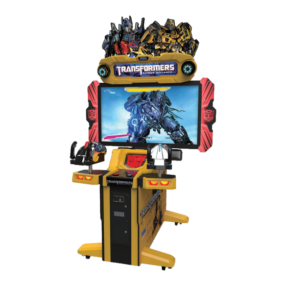
5. PARTS DESCRIPTIONS BILLBOARD (UPPER) BILLBOARD LAMP THE RIGHT SIDE THE LEFT SIDE 1P CONTROLLER 55”LCD 1P START BUTTON 2P CONTROLLER 2P START BUTTON COIN SELECTOR LCD BACKSIDE RIGHT SPEAKER LEFT SPEAKER SERVICE DOOR (MAINFRAME) POWERBOX http://op.sega.jp/op_e/... -
Page 16: Accessories List
TRF-55-0800 The left side billboard plate SCR-E00500 M4*12 chromed Zinc screws M5*16 Cross flat head Combination SCR-E01570 screws SCR-E00450 M8*35 cylinder head screws SCR-E00950 Flat washer 8*20*1(mm) SCR-E00360 M8 flat head spring washer SCR-E01640 M5*25 round cup screws http://op.sega.jp/op_e/... -
Page 17: Installation
7-1 Location of the parts: Billboard Assembly Metal for fixed Billboard and screws:2pcs for each; Fuse:1pcs;AC power cord:1pcs; all the above parts sort out into the coin box. keys are bound on the left side of the right controller http://op.sega.jp/op_e/... -
Page 18: Work Procedures
Locked tightly by 2 pcs of screws (put into the coin box),and then connected by 2pcs of connector and locked tightly upside by 6 pcs of screws (Please see the left picture in green and circle location in blue) and last lock the backside door of the LCD. http://op.sega.jp/op_e/... - Page 19 3 Re-install acrylic the left and right of LCD . Please pay more attention to the direction of the pictures 4 Install host computer Locked tightly by 4 pcs of screws(locked false on the machine) 5 Host computer wire connection: http://op.sega.jp/op_e/...
-
Page 20: Install The Billboard Lamp
Adjust from"7"to "ON" Connect to "COM1" Connect to "DVD"。 Tool: Cross number#2 and Hex Socket M8&M5 7-3 INSTALL THE BILLBOARD LAMP Leg Adjuster Leg Adjuster Castors Castors Castors Castors Leg Adjuster Leg Adjuster http://op.sega.jp/op_e/... -
Page 21: Power Supply And Other Connections
● After laying out the power cord on the floor, be sure to always protect it. If the power cord is left exposed, it can easily be damaged, resulting in electrical shock. Confirm that the main switch is at OFF. MAIN SWITCH Main switch is OFF. FUSE INLET http://op.sega.jp/op_e/... - Page 22 Fully insert the power cord connector on the side opposite the power plug into the AC unit inlet. Fully insert the power cord plug into the outlet. The power cord is laid out indoors. Protect the power cord by attaching wire cover to it. http://op.sega.jp/op_e/...
-
Page 23: Precautions When Moving The Machine
3 Disassemble the left side billboard plate Unscrew 3pcs of M4*25 cross flat head screws with 3mm hexagonal key Steady the side plate to prevent falling down, and handle gently to avoid any scratch on the organic plate. http://op.sega.jp/op_e/... - Page 24 Unscrew 6pcs of M4*25 round cup screws with cross screwdriver and remove the display door. Unplug the lamp power supply cord from the LCD lamp wire connector LCD lamp wire connector Lamp power supply cord 6 Disassemble the billboard http://op.sega.jp/op_e/...
- Page 25 Unscrew 2pcs of M8*35 screws with 6mm hexagonal key it’s ok to move the machine without disassembling in a short distance and enough CASE 2: space. Pay attention to avoid any collision and unnecessary damage when moving the machine http://op.sega.jp/op_e/...
-
Page 26: 9.Game Introduction
GAME SCREEN Player1 and Player2's life gauge, score, streak attack and fatal attack will be displayed on the left screen (player1) and right screen (player2). The available credits and subtitles will be displayed on the bottom of the screen. http://op.sega.jp/op_e/... - Page 27 BASIC CONTROL The player will meet various enemies in the game. If some enemies appear to be outlined, this is the signal to attack. Please rotate the controller and pull the trigger, aim and destroy it before it hurts you. http://op.sega.jp/op_e/...
- Page 28 If the player's life gauge decreases to 0, the game is over. ALLIANCE FIRE When the crosshair of player1 and player2 are close to each other, allied Autobots will show their weapons. The Autobots crosshair will appear between 2 players' crosshairs. http://op.sega.jp/op_e/...
- Page 29 By destroying enemies by Autobots' fire, the "alliance fire" and "times of alliance fire" will display in the screen center. By destroying enemies by Autobots' fire, the "friendship" will be raised with the Autobots. http://op.sega.jp/op_e/...
- Page 30 SUPER ALLIANCE FIRE The player will encounter special enemies carrying energon cubes. These enemies will have blue shinning. After this type of enemies are destroyed, companied Autobots will gain their energon cubes. http://op.sega.jp/op_e/...
- Page 31 Super alliance fire will be triggered in single mode as well. COOP BATTLE As game plays along, players will fight together with Autobots to against a few special Deceptions. These Deceptions will have square attack marks on their body. http://op.sega.jp/op_e/...
- Page 32 If the players can clear all the attack marks before they disappear. This round attack from Deceptions will be resolved, and players will be rewarded extra bonuses. If the players can't clear all the attack marks before they disappear, the players will be attacked to lose "life gauge". http://op.sega.jp/op_e/...
- Page 33 Based on the damage of the marker, diverse result will appear. Based on players' performances in co-op game, the final result screen will be differed. http://op.sega.jp/op_e/...
- Page 34 ACTION SEQUENCE CONTROLS In game process, the mini game called "ACTION SEQUENCE CONTROLS" will take place. Players have to turn laser controller directions or press the button on screen information. http://op.sega.jp/op_e/...
- Page 35 If the players succeed in action, they can avoid Decepticons'' attack and gain extra score bonus. If the players fail in action, "life gauge" will be decreased. http://op.sega.jp/op_e/...
- Page 36 At the end of each level, there will be a Deceptions boss to fight against. Just like in co-op mode, there will be attack markers on these BOSSES. Destroy them before attack markers disappear, the BOSS life gauge will decrease. When the BOSS life gauge decreases to 0, it is defeated. http://op.sega.jp/op_e/...
- Page 37 BOSS captures Bumblebee, and the players successfully destroy all the attack markers, Bumblebee will be rescued, and the "Friendship" between you two will rise. STAGE RESULT & FRIENDSHIP RATE When each level is cleared, "Stage Result" will be displayed. http://op.sega.jp/op_e/...
- Page 38 If the player's life gauge is 0 and doesn't continue, when the countdown is 0, game is over. NAME ENTRY When the game is all cleared, if the total score is in top10, the player can input the name to display in the game ranking. http://op.sega.jp/op_e/...
-
Page 39: Game Test Mode
For the handling of the Test Button.refer to the Test Button(TEST) following pages. Gives credits without registering on the coin Service Button(SERVICE) meter Adjust sound volume for all of the machines’ Sound Volume Switch(SOUND VOLUME) speakers Coin Counter Counts and displayes coins in $0.10 units http://op.sega.jp/op_e/... -
Page 40: Game Test Mode
Tests each input device used for the game. OUTPUT TEST Tests each output device used for the game. GAME ASSIGNMENTS Adjusts all game settings. CONTROLLER CALIBRATION Adjusts aim settings for control units. SETTING BACKUP DATA CLEAR Erases all types of game records. http://op.sega.jp/op_e/... -
Page 41: Bookkeeping
Number of coins inserted in coin chute 2. TOTAL COINS Total Number of coins inserted in coin chute. COIN CREDITS Number of credits for coins inserted. SERVICE CREDITS Number of credits entered with the SERVICE Button. TOTAL CREDITS Total number of all credits. http://op.sega.jp/op_e/... - Page 42 Amount of time the game has been played. AVERAGE GAME TIME Average control time for one game. AVERAGE PLAY TIME Average play time for one game. LONGEST PLAY TIME Longest play time for one game. SHORTEST PLAY TIME Shortest play time for one game. http://op.sega.jp/op_e/...
- Page 43 - Press the TEST Button to return to GAME TEST MODE screen. ■Menu Item Play time will be recorded into different lines by 30 seconds intervals. All play times over 10 minutes are written into the line OVER 10M00S. http://op.sega.jp/op_e/...
-
Page 44: Input Test
“OFF”. SERVICE Press SERVICE button, this item will display “ON”, release the button, the item will display “OFF”. TEST Press TEST button, this item will display “ON”, release the button, the item will display “OFF”. http://op.sega.jp/op_e/... -
Page 45: Output Test
“BLUE”, “RED”, “MAGENTA”, “GREEN”, “CYAN”, “YELLOW”, “WHITE”, “OFF”. PLAYER1 CONTROLLER Player 1 controller vibrates for a period of time. REACTION PLAYER2 CONTROLLER Player 2 controller vibrates for a period of time. REACTION http://op.sega.jp/op_e/... -
Page 46: Game Assignments
Set to open stage select function in stage 2. Set this option “ON” to open stage select. Set to ”OFF” to close stage select. “ON” is set by default. ※Every time this option is changed, the ranking will be cleared. http://op.sega.jp/op_e/... -
Page 47: Controller Calibration Setting
When the controller moves to the extreme position of top left, top right, bottom left and bottom right, if the corresponding crosshair position will be in the very corner of top left, top right, bottom left and bottom right, the crosshair is functional. Otherwise, manual http://op.sega.jp/op_e/... - Page 48 Please note: do not push the controller too hard, just naturally rotate it to proper positions. 2.Execute the same actions above to Player 2’s controller to complete Player 2’s controller calibration setting. 3.Press the TEST button to reflect the calibration settings and go back to CONTROLLER CALIBRATION SETTING screen. http://op.sega.jp/op_e/...
- Page 49 ※ Each time the DEFAULT SETTING is executed, CALIBRATION START need to be executed again to make sure the crosshair position is correct. http://op.sega.jp/op_e/...
-
Page 50: Backup Data Clear
・Select “YES (CLEAR) and press TEST button to clear all backup data. When “COMPLETED” is displayed, press TEST button again and return to GAME TEST MODE screen. ・Select “NO (CANCEL)” and press TEST button, no action will be executed and return to GAME TEST MODE screen directly. http://op.sega.jp/op_e/... -
Page 51: Repair & Maintenance For Controller Part
6.7ohms. 11-2 Repair and maintenance for controller handle infrared. Start the game, put an opaque object into the infrared detector grooves, and check whether the infrared detector is workable. Always keep the infrared detector muzzle clean. http://op.sega.jp/op_e/... -
Page 52: Repair And Maintenance For Mobile Potentiometer (Left And Right)
7mm sleeve Unscrew 3PCS of M4*8 with 3mm hexagonal key Test the Potentiometer with multimeter, and the normal value should be between 0~5K. Regularly clean the gear, and add lubricating oil, so as to keep the gear running smoothly. http://op.sega.jp/op_e/... -
Page 53: Repair And Maintenance For Led Panel
12. HOW TO REPLACE THE PUSH BUTTON SWITCH WHEN THE START BUTTON DOESN’T WORK IN THE INPUT TEST 12-1 Unscrew and remove the STAR BUTTON PLATE. Unscrew 8 PCS of M4*12 with 2.5mm hexagonal key 12-2 Remove the micro-switch from the lamp housing. http://op.sega.jp/op_e/... -
Page 54: Remove The Wiring Harness From The Old Micro-Switch And Re-Attach It To The Replacement Switch In The Same Manner
Disassemble the lamp panel, replace the bad lamp bead after power-on test. The brake light panel (left and right). 13-2 On both sides of the plate lamp maintenance 1 Unscrew the screws(arrow) with 3mm hexagonal key. any skid may lead to damage when disassembling http://op.sega.jp/op_e/... -
Page 55: Maintenance For The Control Table Lamp
RGB lamp bar 55’billboard base plate billboard plate modeling of The 55’left side and right side 55’billboard base plate 13-3 the control table lamp Maintenance for 1 Unscrew the screws(red arrow) with 2.5mm hexagonal key. Pull out the cover gently http://op.sega.jp/op_e/... - Page 56 Unscrew the screws (red arrow) with cross screw driver b) LED_5050.PCB V3.1. Unplug the wire connector and replace the lamp bar(LED_5050.PCB V3.1). c) Follow the original order when installing the red insulating spacer and the colloidal particles prevent any break and leakage. http://op.sega.jp/op_e/...
-
Page 57: Graphics Display
14. GRAPHICS DISPLAY 14-1 LCD component LCD power supply 55’ LCD screen LCD driver board VGA connector power connector Control Panel 14-2 Button Names and Functions http://op.sega.jp/op_e/... -
Page 58: Cleaning & Maintenance For Coin Selector
Remove stain from the rotary shaft and shaftreceiving portions by wiping off with a soft cloth. etc. After wiping off as per previous step, further apply a dry cloth to completely dry the Coin Selector. CRADLE http://op.sega.jp/op_e/... -
Page 59: Coin Insert Test
REJECT Button pressed down and check if it is rejected. 16. HOW TO REPLACE THE PANEL & LIGHTING TUBE FOR BILLBOARD 16-1 Replace the lamp box & lighting tube. isassemble the controller head cover. Unscrew the 8PCS of M4*30 with 2.5mm hexagonal key. http://op.sega.jp/op_e/... - Page 60 2 Unplug the wire connector of controller head lamp panel . Wire connector of Controller head lamp panel . 3 Disassemble the plastic cover of the lamp box. Unscrew the 8PCS of M4*30 with 2.5mm hexagonal key. Unplug the lighting Cut the cable ties tube wire connector. http://op.sega.jp/op_e/...
-
Page 61: Replace The Lamp Panel
Replace the lighting tube. Replace the lighting tube T4(220V 22W)L=700mm. 16-2 Replace the lamp panel. muzzle lamp panel support muzzle PCB lamp plastic nuts Controller scatter plate panel head cover http://op.sega.jp/op_e/... -
Page 62: How To Replace The Lighting Bulb For Start Button
Access to the Start Switch and Lamp housing is gained by first removing the Start Button Plate. Start switch lamp housing 17-2 Remove the Button Plate from the Control Panel to gain access to the Switch and Lamp housing. Unscrew 8PCS of M4*12 with 2.5mm hexagonal key http://op.sega.jp/op_e/... -
Page 63: Once The Button Plate Has Been Removed To Reveal The Switch And Lamp Housing, Do Not Pull The Assembly Arbitrarily, Otherwise, May Lead To The Damage
The Lamp is a push-fit and should not be twisted in its housing. Replacing the lamp with a same type lamp or re-assembling should follow the same instructions. Lamp-LED 5V DC http://op.sega.jp/op_e/... -
Page 64: Common Troubleshooting
3 Installation of the middle potentiometer should read the following figure as reference Adjustment in details please refer to 10-2-6. Flat side of potentiometer should be vertical to the side of controller body. The Copper gear should keep up with the plastic gear on the surface. http://op.sega.jp/op_e/... -
Page 65: Start The Game, The Aim Point In The Screen Cannot Be Movable When Swinging The Controller Up And Down
M4*8 Unscrew 3PCS with hexagonal key 3 Unscrew the M4*8(red arrow) and replace the middle potentiometer. 4 Flat side of potentiometer and angle of controller body’s horizontal plane is about 75 ° adjustment in details please refer to 10-2-6. http://op.sega.jp/op_e/... -
Page 66: Mainframe Position
Base Box The Game Board Unit is located under the Player Seat, and to gain access the following procedure should be carried out. Using cross screwdriver to loosen the screw cross M4*25 Open the base box side door with 919key. http://op.sega.jp/op_e/... - Page 67 Game Board Fixing Points (4) CAUTION Do not open the Game Board without the express permission of SEGA. If for any reason entry has been gained into the Game Board without the permission of SEGA, then all warranty rights become void.
-
Page 68: Cleaning The Ringedge2
Refer to Steps "19-1 RINGEDGE2 - LOCATION" to take the RINGEDGE2 off. Remove the 2 screws and take off the RINGEDGE2 metal filter. The screws are on the reverse side from the connector side. Clean around the air vent of the RINGEDGE2 with a vacuum cleaner. http://op.sega.jp/op_e/... -
Page 69: Composition Of Ringedege2
In some cases, the game cannot be started. DIP SW Setting Use this product with the DIP SW settings shown in the figure below. DIP SW http://op.sega.jp/op_e/... -
Page 70: Error Warnning Display
● When problems occur outside of this booklet record. Do not try to handle on your own. Please cut off the power immediately and contact SEGA agent listed in this booklet or your product purchase location. - Page 71 The I/O board is not correctly used. Solution Please use JVS I/O board which fulfills the game spec. ● PROGRAM SPECIFIC Display Error 1000 Wrong Coin Setting Reason Coin setting is independent, not common. Solution Change coin setting to common. http://op.sega.jp/op_e/...
- Page 72 20 . MENU & CODE For the warning display sticker, please refer to section 1. STS-F00580 - Billboard image STS-F00590 - Lamp box image STS-F00620 - Instruction STS-F00600 - STS-F00610-SEGA LOGO front gate image STS-F00630- STS-F00640- IMAGE Left IMAGE Right http://op.sega.jp/op_e/...
-
Page 73: Parts List
21. PARTS LIST http://op.sega.jp/op_e/... -
Page 74: Final Assembly Drawing(Trf-55-0000
LCD wood Shell TRF-55-0700 LCD assemblies TRF-55-0800 left side of billboard plate TRF-55-0900 right side of billboard plate TRF-55-1000 light box assemblies TRF-GUN-0000 controller assemblies TRF-55-1100 control board wood block TRF-55-1200 base box back gate TRF-55-1300 base box side gate http://op.sega.jp/op_e/... -
Page 75: Mainframe(Trf-55-0100
21-2 mainframe(TRF-55-0100) PARTNUMBER DESCRIPITION TRF-55-0100-S01 supporting stand assemblies TRF-55-0100-S02 electric source box assemblies TRF-55-0100-S03 coin selector assemblies TRF-55-0100-S04 base control plate assemblies TRF-55-0100-S05 test & service button assemblies 21-3 Control board cover assemblies(TRF-55-0200 PARTNUMBER DESCRIPITION DTRF-P00400 Control board cover http://op.sega.jp/op_e/... -
Page 76: Front Cover (Left) For Controller Stand(Trf-55-0300
21-4 front cover (Left) for controller stand(TRF-55-0300) PARTNUMBER DESCRIPITION DTRF-P00600 controller stand front cover (Left) DTRF-H00500 controller stand back lamp plane 21-5 front cover (Right) for controller stand(TRF-55-0400) PARTNUMBER DESCRIPITION DTRF-P00500 controller stand front cover (Right) DTRF-H00500 controller stand back lamp plane http://op.sega.jp/op_e/... -
Page 77: 55' Controller Control Plate Assemblies(Trf-55-0500)
55’ controller stand welding parts DTRF-S01800 Side block panel DTRF-S02000 base block panel DTRF-S01900 lamp panel supporting frame ELE-F00820 DTRF-H00700 controller stand light filter plate 21-7 LCD (TRF-55-0600) wood Shell PARTNUMBER DESCRIPITION DTRF-ASM-W002 LCD wood Shell D55.TRF-S00300 side billboard plate fixed plate http://op.sega.jp/op_e/... -
Page 78: Lcd Assemblies(Trf-55-0700)
Fixed plate3 21-9 The left side billboard plate(TRF-55-0800) PARTNUMBER DESCRIPITION D55.TRF-S00100 55’ cover edge ELE-F00860 Long RGB light bar PMA-B00560 side billboard plate base plate D55.TRF-H001L00 55’ side billboard plate modeling (Left) D55.TRF-S00200 55’ side billboard plate back plate http://op.sega.jp/op_e/... -
Page 79: The Right Side Of Billboard Plate(Trf-55-0900)
D55.TRF-H001R00 55’ right side of billboard plate D55.TRF-S00200 55’ side billboard plate back plate 21-11 Lighting box assemblies(TRF-55-1000) PARTNUMBER DESCRIPITION TRF-55-1010 Billboard assemblies TRF-55-1020 Lighting box cover TRF-55-1030 Controller head cover assemblies TRF-55-1040 Light box front panel assemblies http://op.sega.jp/op_e/... -
Page 80: Controller Assemblies(Trf-Gun-0000)
21-12 controller assemblies(TRF-GUN-0000) 21-13 control board wood block(TRF-55-1100) 21-14 base box back gate(TRF-55-1200) 21-15 base box side gate(TRF-55-1300) http://op.sega.jp/op_e/... -
Page 81: Schematic Diagram
SCHEMATIC DIAGRAM http://op.sega.jp/op_e/... - Page 82 http://op.sega.jp/op_e/...
- Page 83 http://op.sega.jp/op_e/...
- Page 84 http://op.sega.jp/op_e/...