
Related Manuals for Sega Crazy Taxi


Summary of Contents for Sega Crazy Taxi
- Page 1 1st PRINTING May 99 NAOMI CABINET VERSION OWNER’S MANUAL OWNER’S MANUAL OWNER’S MANUAL OWNER’S MANUAL OWNER’S MANUAL SEGA ENTERPRISES, INC. USA MANUAL NO. 4200-6468-01...
- Page 2 Warranty Your new Sega Product is covered for a period of 90 days from the date of shipment. This certifies that the Printed Circuit Boards, Power Supplies and Monitor are to be free of defects in workman- ship or materials under normal operating conditions. This also certifies that all Interactive Control Assemblies are to be free from defects in workmanship and materials under normal operating condi- tions.
- Page 3 VISIT OUR WEBSITE!
-
Page 5: Table Of Contents
TABLE OF CONTENTS INTRODUCTION OF THE OWNERS MANUAL GENERAL PRECAUTIONS 1. PRECAUTIONS TO BE HEEDED FOR OPERATION 2. NAME OF PARTS 3. ACCESSORIES 4. ASSEMBLY AND INSTALLATION 9~15 5. PRECAUTIONS TO BE HEEDED WHEN MOVING MACHINE 6. CONTENTS OF GAME 17~19 7. -
Page 6: Introduction Of The Owners Manual
29” NANAO MONITOR INTRODUCTION OF THE OWNERS MANUAL SEGA ENTERPRISES, LTD., has for more than 30 years been supplying various innovative and popular amusement products to the world market. This Owners Manual is intended to provide detailed descriptions together with all the necessary installation, game settings and parts ordering information related to CRAZY TAXI Naomi Cabinet type, a new SEGA product. -
Page 7: General Precautions
General Precautions Follow Instructions: All operating and use instructions should be followed. Attachments: Do not use attachments not recommended by the product manufacturer as they may cause hazards. Accessories: Do not place this product on an unstable cart, stand, tripod, bracket, or table. The product may fall, causing serious injury to a child or adult, and serious damage to the product. - Page 8 Safety Check: Upon completion of any service or repairs to this product, ask the service technician to perform safety checks to determine that the product is in proper operating condition. Heat: The product should be situated away from heat sources such as radiators, heat registers, stoves, or other prod- ucts (including amplifiers) that produce heat.
-
Page 9: Precautions To Be Heeded For Operation
1 . PRECAUTIONS TO BE HEEDED FOR OPERATION In order to prevent accidents, be sure to comply with the following points before and during operation. PRECAUTIONS TO BE HEEDED FOR OPERATION BEFORE STARTING THE OPERATION In order to avoid accidents, check the following before starting the operation: Check if all of the adjusters are in contact with the surface. - Page 10 PRECAUTIONS TO BE HEEDED DURING OPERATION To avoid injury and accidents, those who fall under the following catagories are not allowed to play the game: * Intoxicated persons * Those who have high blood pressure or heart problems. * Those who have experienced muscle convulsion or loss of consciousness when playing video games, etc.
-
Page 11: Name Of Parts
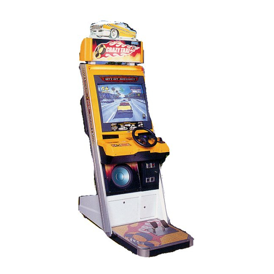
2 . NAME OF PARTS WEIGHT lbs. WIDTH in. LENGTH in. HEIGHT in. GAME SPECIFICATIONS 40” 70” 100” ~ 425 LBS. DURING SHIPPING 325 LBS. CABINET 30” 41” 71” 25” 28” 6” FLOOR 42 LBS. BILLBOARD 30” 6.5” 12” 13 LBS. WHEN ASSEMBLED 30”... -
Page 12: Accessories
3 . ACCESSORIES... - Page 13 TO ALL ‘MODEL 3’ OR ‘NAOMI’ BOARDS CONTAINED IN THE FOLLOWING GAMES: LOST WORLD, VIRTUA FIGHTER 3, SUPER GT, SEGA BASS FISHING, STRIKER 2 HARLEY DAVIDSON, RALLY 2, DAYTONA 2, DIRT DEVILS, HOUSE OF THE DEAD 2, OCEAN HUNTER, STAR WARS TRILOGY, ZOMBIE REVENGE, CRAZY TAXI...
-
Page 14: Assembly And Installation
4 . ASSEMBLING AND INSTALLATION Assembling should be performed as per this manual. Since this is a complex machine, erroneous assembling may cause damage to the machine, or malfunctioning to occur. When assembling, be sure to perform work by plural persons. Depending on the assembly work, there are some cases in which performing the work by a single person can cause personal injury or parts damage. - Page 15 Unlock and remove the SERVICE DOOR from the front of the cabinet. Remove the Plastic nut of the Connector at the end of ASSY FLOOR’s Fexible Tube. Insert the Connector at the end of the Flexible Tube into the round hole on the bottom of cabinet from the underside, and secure by fastening the plastic nut.
- Page 16 ASSY OF THE BILLBOARD Due to its large size, it is very difficult for one person alone to install the billboard, Make sure 2 or more persons are available to perform this work. Attempting to perform the installation alone can cause an accident. Mount Billboard on cabinet by ensuring the front lip of the Billboard is securely placed under the mounting bracket already installed on the cabinet.
- Page 17 SECURING IN PLACE (ADJUSTER ADJUSTMENT) Be sure to have all the Adjusters make contact with the surface. Un- less the Adjusters come into contact with the surface, the Cabinet can move of itself, causing an accident. This machine has 4 each of casters and adjusters (shown below). When the installation position is determined, cause the adjusters to come into contact with the floor directly, make adjustments in a manner so that the casters will be raised approximately 5mm.
- Page 18 POWER SUPPLY Ensure that the power cord is not exposed on the surface (passage, etc.). If exposed, they can be caught and are susceptible to damage. If damaged, the cord can cause an electric shock or short circuit. Ensure that the wiring position is not in the customer's passage way or the wiring has protective covering.
- Page 19 ASSEMBLING CHECK The TEST MENU allows for each part of the cabinet to be checked, the Monitor to be adjusted, and the coin and game related various functions to be performed. Selecting the MEMORY TEST on the test mode menu screen causes the on-board memory to be tested automatically. The game board is satisfactory if the display beside each IC No.
- Page 20 SOUND TEST In the TEST mode, selecting SOUND TEST causes the screen, on which sound related BD and wiring connec- VOICE tions are tested, to be displayed. Be sure to check if the EFFECT sound is satisfactorily emitted from each of speaker and the sound volume is appropriate.
-
Page 21: Precautions To Be Heeded When Moving Machine
5 . PRECATIONS TO BE HEEDED WHEN MOVING THE MACHINE When moving the machine, be sure to pull out the plug from the power supply. Moving the machine with the plug as is inserted can damage the power cord and cause a fire or elec- tric shock. -
Page 22: Contents Of Game
6 . CONTENTS OF GAME The following explanations apply to the case the product is functioning satisfactorily. Should there be any moves different from the following contents, some sort of faults may have occured. Immediately look into the cause of the fault and eliminate the cause thereof to ensure satisfactory operation. - Page 23 HOW TO PLAY Insert a coin. Coin insertion causes credit(s) to be displayed on the screen. For example, in the case of 2 coins one credit setting, “INSERT COIN(S) CREDIT(S) 1/2” is displayed when one coin is inserted. Inserting one play worth of coin(s) causes “PRESS START BUTTON” to be displayed and the START BUTTON to flash.
- Page 24 The following explains as regards how to earn FARE (or score points). The minimum fare is earned at the time the taxi picks up the Customer. Basically, the best way to earn FARE is to take the Customer to their destiantion as fast as possible. In other words, since the time remaining when reaching the destination is converted into FARE, the more remaining time is, the greater the FARE the player earns.
-
Page 25: Explanation Of Test And Data Display
7 . EXPLANATION OF TEST AND DATA DISPLAY By operating the switch unit, periodically perform the tests and data check. When installing the machine initially or collecting cash, or when the machine does not function correctly, perform checking in accordance with the explanations given in this section. -
Page 26: Switch Unit And Coin Meter
7 - 1 SWITCH UNIT AND COIN METER Never touch places other than those specified. Touching places not specified can cause electric shock and short circuit. Adjust to the optimum sound volume by considering the environmental requirements of the installation location. If the COIN METER and the game board are electrically disconnected, game play is not possible. -
Page 27: System Test Mode
7 - 2 SYSTEM TEST MODE The contents of setings chnaged in the TEST mode are stored when the TEST mode is finished from EXIT in the MENU mode. If the power is turned off before the TEST mode is finished, the contents of setting chnage become ineffective. Executing “BACKUP DATA CLEAR”... -
Page 28: Input Test
7 -4 INPUT TEST Select INPUT TEST to have the screen shown below appear and to observe the status of each switch and the value of each V.R. on the Control Panel. Periodically check the status of each switch and V.R. on this screen. By pressing each switch, if the display on the right-hand side of the name of each switch changes to ON from OFF, the SW and the wiring connections are satisfactory. -
Page 29: Sound Test
7 - 6 SOUND TEST SOUND TEST This test mode allows each sound related board and speaker to be checked. VOICE EFFECT B.G.M Press the Service Button to select the sound to be tested, >EXIT and press the Test Button to have the selected Sound Test screen appear. -
Page 30: Volume Setting
7 - 8 VOLUME SETTING When VOLUME SETTING is selected, the following appears on the screen and each operating unit’s Volume can be set. If the operability is unsatisfactory, or when the Volume is adjusted or replaced, set the Volume in this mode. The 3 kinds of Volume Settings for HANDLE, ACCEL, and BRAKE are to be set. -
Page 31: Game Assignments
7 - 9 GAME ASSIGNMENTS Selecting the GAME ASSIGNMENTS in the MENU mode causes the present game settings to be displayed and also the game settings changes (game difficulty, etc.) can be made. Each item displays the following content. SETTING CHANGE PROCEDURE Press the SERVICE BUTTON to move the “>”... -
Page 32: Coin Assignments
7 - 10 COIN ASSIGNMENTS The “COIN ASSIGNMENTS” mode permits you to set the start number of credits, as well as the basic numbers of coins and credits. This mode expresses “how many coins correspond to how many credits.” SETTING CHANGE PROCEDURE Setting changes cannot be stored unless the TEST BUTTON is pressed while the arrow is on EXIT. - Page 33 TABLE 7.10a COIN/CREDIT SETTING (COIN CHUTE COMMON TYPE) SETTING FUNCTIONING OF CHUTE#1 SETTING #1 1 COIN 1 CREDIT SETTING #2 1 COIN 2 CREDITS SETTING #3 1 COIN 3 CREDITS SETTING #4 1 COIN 4 CREDITS SETTING #5 1 COIN 5 CREDITS SETTING #6 1 COIN...
- Page 34 MANUAL SETTING Selecting MANUAL SETTING in the COIN ASSIGNMENTS mode displays the following screen. MANUAL SETTING COIN TO CREDIT 1 COIN 1 CREDIT BONUS ADDER NO BONUS ADDER COIN CHUTE #1 MULTIPLIER 1 COIN COUNTS AS 1 COIN COIN CREDIT COIN CHUTE #2 MULTIPLIER 1 COIN COUNTS AS 1 COIN COIN...
-
Page 35: Bookkeeping
7 - 11 BOOKKEEPING Choosing BOOKKEEPING in the MENU mode displays the data of operating status up to the present are shown on 2 pages. Press the TEST BUTTON to proceed to PAGE 2/2. COIN CHUTE#*: BOOKKEEPING PAGE1/3 Number of coins put in each Coin Chute. COIN CHUTE #1 XXXXXXXXXXX COIN CHUTE #2... -
Page 36: Control Panel (Handle Mecha) 31~33
8. CONTROL PANEL (HANDLE MECHA) In order to prevent an electric shock and short circuit, be sure to turn power off before performing work by touching the interior parts of the product. Be careful so as not to damage wirings. Damaged wiring can cause an electric shock or short circuit accident. - Page 37 Loosen the 2 screws and adjust the angle and appropriateness of gear mesh by moving the VR Bracket. Adjust to an appropriate mesh by securing the Steering Wheel in the direction allowing the car to advance straight forward and ensuring the “D” CUT FACE of the Volume Shaft is oriented as shown.
-
Page 38: Greasing
8 - 2 GREASING Never touch places other than those specified. Touching places not specified can cause electric shock and/or short circuit. After the replacement or adjustment of the VR, be sure to set the variable value of the VR in the test mode’s Volume Setting. Apply greasing to the Volume gear mesh portion every 3 months. -
Page 39: Shift Lever
9. SHIFT LEVER In order to prevent electric shock and short circuit, be sure to turn off the power before performing work on the interior parts of the product. Be careful not to damage wiring. Damaged wiring can cause electric shock or short circuit. -
Page 40: Switch Replacement
9 - 2 SWITCH REPLACEMENT Each microswitch is secured with 2 screws. Remove the 2 screws and replace the Microswitch. After replacing the Switch, check to see if the switch is inputted as per Shift Lever Operation in the Test Mode. 9 - 3 GREASING Apply greasing once in 3 months to the specified portions. -
Page 41: Accel & Brake
10. ACCEL & BRAKE In order to prevent an electric shock and short circuit, be sure to turn power off before performing work by touching the interior parts of the product. Be careful so as not to damage wirings. Damaged wiring can cause an electric shock or short circuit accident. - Page 42 Take out the 6 Hexagon Nuts to remove the Accelerator (Brake) Unit. Disconnect the connector and remove the Accel- erator (Brake) Unit.
-
Page 43: Adjusting Or Replacing The Volume
10 - 2 ADJUSTING OR REPLACING THE VOLUME ADJUSTMENT Loosen the 2 screws, move the VR Bracket, and adjust the angle and appropriateness of gear mesh. REPLACEMENT Take out the 2 screws and remove the Volume together with the V.R. Bracket. After replacing the Voume, engage the gears at the angle shown, and fix the V.R. -
Page 44: Greasing
10 - 3 GREASING Be sure to use designated grease. Using undesignated grease can cause parts damage. Do not apply grease to undesignated areas. Failure to observe this can cause malfunctioning or quality deterioration of parts. Before starting work, ensure the Power SW is OFF. Failure to observe this can cause electric shock and short circuit hazards. -
Page 45: Coin Selector
11 . COIN SELECTOR HANDLING THE COIN JAM If the coin is not rejected when the REJECT BUTTON is pressed, open the coin chute door and open the selector gate. After removing the jammed coin, put a normal coin in and check to see that the selector correctly functions. - Page 46 OPTIONAL DOLLAR BILL ACCEPTOR THE COIN DOOR ASSEMBLY USED ON CRAZY TAXI CRAZY TAXI CRAZY TAXI CRAZY TAXI CRAZY TAXI COMES EQUIPPED TO ACCEPT A DOLLAR BILL ACCEPTOR. ALL NEEDED WIRING CONNECTIONS ARE CONVIENENTLY LOCATED INSIDE THE GAME FOR THIS APPLICATION.
-
Page 48: Monitor
(plug) before starting work. Proceeding the work without following this instruction can cause electric shock of malfunctioning. Using the monitor by converting it without obtaining a prior permission is not allowed. SEGA shall not be liable for any malfunctioning and accident caused by said conversion. -
Page 49: Monitor
For the purpose of static prevention, special coating is applied to the CRT face of this product. To protect the coating, pay attention to the following points. Damaging the coating film can cause electric shock to the customers. For the caution to be heeded when clearing, refer to the Section of Periodic inspection Table. -
Page 51: Replacement Of Fluorescent Lamp
13. REPLACEMENT OF FLUORESCENT LAMP When performing the work, be sure to turn power off. Working with power on can cause an electric shock or short circuit acci- dent. The Fluorescent Lamp, when it gets hot, can cause burns. Be very careful when replacing the Fluorescent Lamp. - Page 52 4 By using a Flat-blade screw- driver, etc.remove the 4 Screw Caps from the Front Panel. 4 Take out the 4 Tamperproof screws and 2 screws, and remove the Front Panel to replace the Fluorescent Lamp.
- Page 53 INTERIOR OF BILLBOARD 1 Take out the 4 screws and remove the Plate Holder. 2 Remove the Billboard Plate and replace the Fluorescent Lamp.
-
Page 54: Periodic Inspection Table
14. PERIODIC INSPECTION TABLE The items listed below require periodic check and maintenance to retain the performance of this machine and ensure safe operation. Be sure to check once a year to see if Power Cords are damaged, the plug is securley inserted, dust is accumulated between the Socket Outlet and the Power Plug, etc. -
Page 55: Troubleshooting
15. TROUBLESHOOTING Should trouble occur, first check connector connections. PROBLEMS CAUSE COUNTERMEASURES With Main SW Power is not supplied. Plug in correctly ON, no activation Power supply/voltage is not correct. Make sure that power supply/voltage is correct. AC main fuse causes the Check fuse. -
Page 56: Game Board
16. GAME BOARD In order to prevent an electrical shock, be sure to turn power off before performing work by touching the interior parts of the product. Be careful so as not to damage wirings. Damaged wiring can cause an electric shock or short circuit accident. -
Page 57: Composition Of The Game Board
16 - 3 COMPOSITION OF GAME BOARD Ensure that the DIP SW setting is performed as designated as designated. Failure to observe this may cause functioning not suitable for the operation, or malfunc- tioning. ASSY CASE NAO USA (840-0002D-01) :USA DIP SW SETTING IN the product, set all of the DIP SWes to OFF. -
Page 58: Design Related Parts
17. DESIGN RELATED PARTS... - Page 59 DESIGN RELATED ITEM NO. PART NO. DESCRIPTION 422-0732-01 PLAY INSTRUCTION SH CTA ENG 422-0733-01 SUB INSTR SH CTA ENG 429-0638 POP CTA CTA-1009 STICKER SIDE L CTA-1010 STICKER SIDE R NOA-1507 EMBLEM NAOMI CTA-1404 STICKER FRONT CTA-1405 STICKER F INY-1203-B SHEET EMBLEM CTA-2001-C GUARD PLATE CENTER...
-
Page 60: Parts List 55~82
18. PARTS LIST TOP ASSY CRAZY TAXI... - Page 61 TOP ASSY CTA ITEM NO. PART NO. DESCRIPTION CTA-1000 ASSY U/R CABI CTA-1500 ASSY FLOOR CTA-0001 JOINT BRKT L CTA-0002 JOINT BRKT R JEY-0005 DENOMI PLATE LOCAL PURCHASE DENOMI SH 1 GAME 422-0732-01 PLAY INSTR SH CTA 422-0749-01 STICKER HIGH RANK 422-0733-01 SUB INSTR SH CTA 030-000820-SB...
- Page 62 ASSY U/R CABI (CTA-1000)
- Page 63 ASSY U/R CABI (CTA-1000) ITEM NO. PART NO. DESCRIPTION CTA-1100 ASSY FRAMEWORK UR NOA-1200 ASSY CRT COVER CTA-1300 ASSY BILLBOARD CTA-1400 ASSY CONTROL BOX CTA-1150 ASSY CC BOX WW NOA-4000 ASSY ELEC NOA-1750 ASSY SERVICE DOOR NOA-1801 REAR HATCH NOB-1001 FRAME COVER U/R R NOB-1002 FRAME COVER U/R L...
- Page 64 ASSY FRAMEWORK (CTA-1100)
- Page 65 ASSY FRAMEWORK (CTA-1100) ITEM NO. PART NO. DESCRIPTION NOA-1601 BASE BOX NOB-1101 MAIN FRAME UR R NOB-1102 MAIN FRAME UR L NOA-1111 LOWER BEAM NOA-1112 UPPER BEAM NOA-1113 HOOF R NOA-1114 HOOF L HOT-1200 ASSY CASH BOX DOOR BOX-CASH CASH BOX NOA-11115 TNG REAR HATCH 220-5643-01...
- Page 66 ASSY CASH BOX DOOR (HOT-1200) ITEM NO. PART NO. DESCRIPTION HOT-1201 CASH BOX DOOR 220-5574 CAM LOCK W/KEYS HOT-1203 CENTER TNG HOT-1204 SIDE TNG 065-E00300 E RING 3MM...
- Page 67 ASSY CC BOX WW (CTA-1150) ITEM NO. PART NO. DESCRIPTION CTA-1151 CC BOX WW DP-1167 TNG LKG CTA-1153 CHUTE W CTA-1160 SW UNIT 97-1003-05 ASSY C.C.CHUTE DOOR 220-5575 CAM LOCK MASTER W/O KEY...
- Page 68 ASSY SW UNIT (CTA-1160) ITEM NO. PART NO. DESCRIPTION CTA-1161 SW BRKT 220-5179 VOL CONT B-5K OHM 601-0042 KNOB 22MM 509-5028 SW PB 1M...
- Page 69 ASSY CRT COVER (NOA-1200) ITEM NO. PART NO. DESCRIPTION NOA-1201 CRT COVER NOA-1202 SPEAKER BOX 130-5205 SPEAKER 4OHM 10W 100 W/SHIELD 000-P00410-W M SCR PH W/FS M4X10...
- Page 70 ASSY BILLBOARD (CTA-1300) ITEM NO. PART NO. DESCRIPTION CTA-1301 BILLBOARD COVER L CTA-1302 BILLBOARD COVER R CTA-1303 BILLBOARD BASE CTA-1304 PLATE HOLDER 423-0329 BILLBOARD PLATE PLATE CTA...
- Page 71 ASSY FRONT PANEL (CTA-1400) ITEM NO. PART NO. DESCRIPTION CTA-1401 FRONT PANEL NOA-1502-01 MASK MS9 NOA-1503 LIGHT COVER NOA-1504 PRISM PLATE CTA-1402 LID GCS CTA-1403 LID VMS NOA-1507 EMBLEM NAOMI CTA-1404 STICKER FRONT CTA-1405 STICKER F 000-P00416-W M SCR PH W/FS M4X12...
- Page 72 ASSY AC UNIT (NOC-1700) ? ITEM NO. PART NO. DESCRIPTION NOB-1701 AC BRKT 509-5876 LOCKER SW JW-L21RKK 214-0202 AC INLET PANEL TYPE 512-5046-5000 C.P. 5000MA CE UL 000-P00308-W M SCR PH W/FS M3X8 050-H00400 HEX NUT M4 060-F00400 FLT WSHR M4 060-S00400 SPR WSHR M4...
- Page 73 ASSY CONTROL PANEL (CTA- 2000)
- Page 74 ASSY CONTROL PANEL (CTA- 2000) ITEM NO. PART NO. DESCRIPTION CTA-2001 CONTROL PANEL COVER CTA-2002 CONTROL PANEL BRKT CTA-2003 HINGE 456 CTA-2100 ASSY HANDLE MECHA 610-0408 UP/DOWN SHIFTER AL DYN-1201 STEERING WHEEL DYN-1209X HANDLE COLLAR INY-1203-B STEERING EMBLEM OUT-2026 SPACER CTA-2004 STICKER SHIFT D CTA-2005...
- Page 75 ASSY HANDLE MECHA (CTA-2100)
- Page 76 ASSY HANDLE MECHA (CTA-2100) ITEM NO. PART NO. DESCRIPTION CTA-2101 HANDLE BASE CTA-2101 BASE LID CTA-2103 HANDLE SHAFT CTA-2104 STOPPER BOLT CTA-2105 SPRING HOOK CTA-2106 SPACER RING CTA-2107 VR BRKT DYN-1262 SWING ARM SHAFT DYN-1269 EXT SPRING DYN-1273 SWING ARM BVG-1340 FLT WSHR 8.1-12X2 BVG-1341...
- Page 77 ASSY WOOFER (CTA-2200) ITEM NO. PART NO. DESCRIPTION CTA-2202 WOOFER BRKT L CTA-2203 WOOFER BRKT R CTA-2204 WOOFER BRKT UPPER CTA-2205 WOOFER BRKT LOWER 423-0328 WOOFER PLATE 130-5208 WOOFER BOX 2OHM 75W 000-P00520-WB M SCR PH W/FS BLK M5X20 000-T00560-0B M SCR TH BLK M5X60...
- Page 78 ASSY ELEC (NOA-4000) ITEM NO. PART NO. DESCRIPTION NOA-4001 ELEC BASE 400-5397 SW REGU FOR JVS 560-5407-UL AUDIO XFMR 120V 17V2.1AX2 838-13616 AUDIO POWER AMP 2 CH 838-11856-UL CONNECT BD UL 509-5876 LOCKER SW JW-L21RKK 601-6231-B60 EDGING NEW TYPE L=60 010-P00406-F S-TITE SCR PH W/F M4X6 010-P00306-F...
- Page 79 ASSY MAIN BD (CTA-4100) ITEM NO. PART NO. DESCRIPTION CTA-4101 WOODEN BASE MAIN 840-0002D-01 ASSY CASE NAO CTA USA 838-13758 LOWPASS AMP CTA 838-13759 RECT BD CTA 560-5413-V XFMR 100V 12.8V6.3A 000-P00408-W M SCR PH W/FS M4X8...
- Page 80 ASSY SHIELD CASE NAO (840-0002D-01) ITEM NO. PART NO. DESCRIPTION 840-0001A-01 SHIELD CASE CTA NAO USA 840-0001C ROM CASE NAO...
- Page 81 ASSY FLOOR (CTA-1500)
- Page 82 ASSY FLOOR (CTA-1500) ITEM NO. PART NO. DESCRIPTION CTA-1501 FLOOR BASE CTA-1600 ACCEL UNIT CTA-1650 BRAKE UNIT CTA-1502 LEVEL ADJUSTER CTA-1503 FLOOR MAT CTA-1504 CORNER PROTECTOR CTA-1505 SASH SIDE CTA-1507 SASH REAR CTA-1508 FLOOR LID 000-T00408-0C M SCR TH CRM M4X8 050-H00600 HEX NUT M6 050-H01000...
- Page 83 ASSY ACCEL UNIT (CTA-1600)
- Page 84 ASSY ACCEL UNIT (CTA-1600) ITEM NO. PART NO. DESCRIPTION CTA-1601 PEDAL BASE CTA-1602 ACCEL PEDAL CTA-1603 PEDAL SHAFT CTA-1604 STOPPER BLOCK CTA-1605 RUBBER PLATE CTA-1606 RUBBER CASE CTA-1607 VR BRKT HLD-2805 TORSION SPRING HLD-2808 RUBBER HOLDER 601-6450 GEAR 110 601-7944 GEAR 15 CTA-1608 SUPPORT BRKT...
- Page 85 ASSY BRAKE (CTA-1650)
- Page 86 ASSY BRAKE (CTA-1650) ITEM NO. PART NO. DESCRIPTION CTA-1601 PEDAL BASE CTA-1651 BRAKE PEDAL CTA-1603 PEDAL SHAFT CTA-1604 STOPPER BLOCK CTA-1605 RUBBER PLATE CTA-1606 RUBBER CASE CTA-1607 VR BRKT HLD-2805 TORSION SPRING HLD-2808 RUBBER HOLDER 601-6450 GEAR 110 601-7944 GEAR 15 CTA-1608 SUPPORT BRKT 220-5373...
- Page 87 ASSY XFMR (NOA-4100) ITEM NO. PART NO. DESCRIPTION NOB-4101 XFMR BASE 560-5426-V XFMR 100-120V 100V5.5A 514-5093 FUSE HOLDER F-64AB COVER LOCAL PURCHASE FUSE 5000MA 000-P00416-W M SCR PH W/FS M4X16 011-T03512 TAP SCR TH 3.5X12 011-P00312 TAP SCR PH 3X12...