Table of Contents
Advertisement
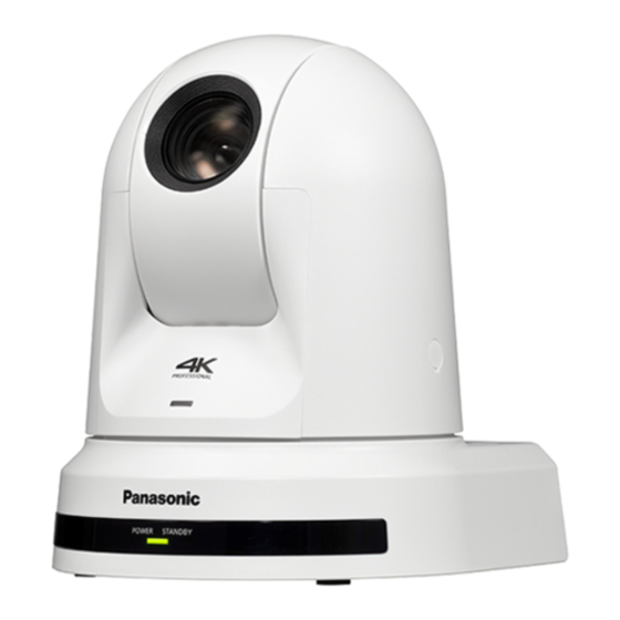
AW‑UE50WP
Model No.
AW‑UE50KP
Model No.
AW‑UE50WE
Model No.
AW‑UE50KE
Model No.
AW‑UE50WED
Model No.
AW‑UE50KED
Model No.
Before operating this product, please read the instructions carefully and save this manual for future use.
Please carefully read the "Read this first!" (pages 2 to 5) of this Manual before use.
PJ EJ ED
W0122GU0 -FJ
Operating Instructions
4K Integrated Camera
Model No.
Model No.
Model No.
Model No.
Model No.
Model No.
AW‑UE40WP
AW‑UE40KP
AW‑UE40WE
AW‑UE40KE
AW‑UE40WED
AW‑UE40KED
ENGLISH
DVQP2618ZA
Advertisement
Table of Contents

Related Manuals for Panasonic AW-UE50WP


Summary of Contents for Panasonic AW-UE50WP
- Page 1 Operating Instructions 4K Integrated Camera AW‑UE50WP AW‑UE40WP Model No. Model No. AW‑UE50KP AW‑UE40KP Model No. Model No. AW‑UE50WE AW‑UE40WE Model No. Model No. AW‑UE50KE AW‑UE40KE Model No. Model No. AW‑UE50WED AW‑UE40WED Model No. Model No. AW‑UE50KED AW‑UE40KED Model No. Model No. Before operating this product, please read the instructions carefully and save this manual for future use.
-
Page 2: Read This First! (For Aw-Ue50Wp, Aw-Ue50Kp, Aw-Ue40Wp, Aw-Ue40Kp)
Operation at a voltage other than 120 V AC may require the use of a different AC plug. Please contact either a local or foreign Panasonic authorized service center for assistance in selecting an alternate AC plug. indicates safety information. - Page 3 FCC NOTICE (USA) Supplier’s Declaration of Conformity Model Number: AW-UE50WP/AW-UE50KP/AW-UE40WP/AW-UE40KP Trade Name: Panasonic Responsible Party: Panasonic Corporation of North America Two Riverfront Plaza, Newark, NJ 07102 Support contact: 1-800-524-1448 This device complies with part 15 of the FCC Rules. Operation is subject to the following two conditions: (1) This device may not cause harmful interference, and (2) this device must accept any interference received, including interference that may cause undesired operation.
-
Page 4: Read This First
If you lose the fuse cover the plug must not be used until a replacement cover is obtained. Fuse A replacement fuse cover can be purchased from your local Panasonic Dealer. indicates safety information. The symbols on this product (including the accessories) represent the following:... -
Page 5: Read This First! (For Aw-Ue50We, Aw-Ue50Ke, Aw-Ue40We, Aw-Ue40Ke)
For more information about collection and recycling, please contact your local municipality, dealer or supplier. Penalties may be applicable for incorrect disposal of this waste, in accordance with national legislation. Manufactured by: Panasonic Corporation, Osaka, Japan Importer’s name and address of pursuant to EU rules:... -
Page 6: Read This First
• Android™ and Chrome™ browser are trademarks of Google LLC. Model number of unit manual • Intel ® and Intel ® Core™ are trademarks or registered trademarks AW-UE50WP, AW-UE50KP, of Intel Corporation in the United States and other countries. AW-UE50WE, AW-UE50KE, AW‑UE50 • Adobe ® and Reader ®... -
Page 7: Table Of Contents
Contents Read this first! (For AW‑UE50WP, AW‑UE50KP, AW‑UE40WP, Matrix 2/5 screen ................51 AW‑UE40KP) ..................2 Matrix 3/5 screen ................52 Matrix 4/5 screen ................52 Read this first! (For AW‑UE50WE, AW‑UE50KE, AW‑UE50WED, AW‑UE50KED, AW‑UE40WE, AW‑UE40KE, AW‑UE40WED, Matrix 5/5 screen ................53 AW‑UE40KED) ................... -
Page 8: Before Use
Safari 14.01 it can be operated via a web browser. macOS v11.0.1 Google Chrome • Connection with a Panasonic camera controller is also possible via Panasonic's proprietary serial communication format. macOS V10.15 Google Chrome • The unit is available in white (AW-UE50W/AW-UE40W) or black macOS V10.14... -
Page 9: Disclaimer Of Warranty
Panasonic does not accept any responsibility for damage of this type. https://pro-av.panasonic.net/ • Use the unit in a network secured by a firewall, etc. -
Page 10: Features
AW-RP60). The unit can also be used together with the cameras and pan-tilt [HD format (SDI supported)] head unit systems currently available from Panasonic Corporation 1080/59.94p, 1080/50p, 1080/59.94i, 1080/50i, 1080/29.97p , so that an existing system can be used to advantage to put 1080/25p ... -
Page 11: Accessories
Features (continued) PoE+ eliminates need for camera power • Use a Category 5e cable or higher when using a PoE+ power „ „ supply. The maximum length of the cable between the power configurations supply unit and the unit is 100 meters (328 ft). Using a cable that •... -
Page 12: Operating Precautions
Operating precautions Do not use the unit in oily‑smoky or dusty What happens with high‑brightness subjects „ „ „ „ Flare may occur if an extremely bright light source is pointed at places. the lens. In a case like this, change the angle or take some other Performance may be adversely affected if small particles or other remedial action. - Page 13 Operating precautions (continued) Concerning PoE+ power supply Transportation „ „ „ „ The unit complies with the IEEE 802.3at. The camera unit is constructed to rotate easily. As malfunctions in Use a compatible Ethernet hub and PoE+ injector to use a PoE+ camera movement may occur, transport after securing the camera power supply.
- Page 14 This product includes MIT Licensed software. This product includes BSD Licensed software. For details on obtaining the source codes, visit the following website. https://pro-av.panasonic.net/ However, do not contact Panasonic for questions regarding obtained source codes.
-
Page 15: Wireless Remote Control (Optional Accessory)
Wireless remote control (optional accessory) This unit can be operated by remote control using a wireless <Layout of wireless remote control signal light‑sensing areas> remote control (model number: AW‑RM50AG) purchased separately. <NOTE> Check out the following points before using the wireless remote •... -
Page 16: Parts And Their Functions
Parts and their functions Mount bracket for installation surface (supplied Camera unit accessory) Mount this bracket onto the installation surface, and then attach the camera main unit to the bracket. Drop‑prevention wire This wire is screwed down to the bottom panel of the camera main unit. - Page 17 Parts and their functions (continued) Service switches <SERVICE> <NOTE> • Do not connect PoE cable to the RS-422 port. Perform switch settings before turning the unit on. • Do not apply a voltage to the R_TALLY_IN signal pin. • [AW‑UE50] Service switches The ON/OFF for red tally signals or green tally signals received by this unit can be output via pin 7 or pin 8.
- Page 18 Parts and their functions (continued) LAN connector for IP control <LAN LINK/ACT> This LAN connector (RJ-45) is connected when exercising IP control over the unit from an external device. Use a LAN cable (category 5e or above, STP, max. 100 m (328 ft)) for connection. Use of an STP (Shielded Twisted Pair) cable is recommended.
- Page 19 Parts and their functions (continued) Output conditions for each video format „ „ [AW‑UE50] Frequency System Format HDMI 3G SDI OUT 2160/29.97p 2160/29.97p 1080/29.97p 1080/59.94p 1080/59.94p 1080/59.94p 1080/59.94i 1080/59.94i 1080/59.94i 1080/59.94i 59.94Hz 1080/29.97p 1080/29.97p 1080/29.97p 1080/29.97PsF 1080/29.97p 1080/29.97PsF 1080/23.98p over 59.94i 1080/23.98p over 59.94p 1080/23.98p over 59.94i 720/59.94p...
- Page 20 Parts and their functions (continued) IP video transmission output (multi‑channel display) „ „ • When “Streaming mode” is set to “H.265” Settings H.265(1) H.265(2) H.264(1) H.264(2) H.264(3) H.264(4) JPEG(1) JPEG(2) JPEG(3) 1920×1080 1920×1080 1920×1080 1280×720 1280×720 1280×720 Resolution — — —...
- Page 21 Parts and their functions (continued) • When “Streaming mode” is set to “H.264” Settings H.265(1) H.265(2) H.264(1) H.264(2) H.264(3) H.264(4) JPEG(1) JPEG(2) JPEG(3) 1920×1080 1920×1080 1920×1080 1280×720 1280×720 1280×720 1280×720 1280×720 Resolution — — 640×360 640×360 640×360 640×360 640×360 640×360 320×180 320×180 320×180...
- Page 22 Parts and their functions (continued) • When “Streaming mode” is set to “RTMP” Settings H.265(1) H.265(2) H.264(1) H.264(2) H.264(3) H.264(4) JPEG(1) JPEG(2) JPEG(3) 1920×1080 1920×1080 1280×720 1280×720 Resolution — — — — — 640×360 640×360 640×360 320×180 320×180 320×180 60fps 30fps 30fps 30fps...
- Page 23 Parts and their functions (continued) • When “Streaming mode” is set to “NDI|HX V2” Settings NDI|HX JPEG(1) 1920×1080 1280×720 1280×720 Resolution 640×360 320×180 60fps 30fps 30fps System frequency 15fps 15fps 59.94Hz 5fps 5fps 1fps 50fps 25fps 25fps System 12.5fps 12.5fps frequency 50Hz 5fps...
-
Page 24: Wireless Remote Control: Aw-Rm50Ag (Optional Accessory)
Parts and their functions (continued) MODE button <MODE> Wireless remote control: AW‑RM50AG (optional This is used to select the video signals which are output from the unit. accessory) Each time it is pressed, the signals are switched between the color bar signals and camera video signals. - Page 25 Parts and their functions (continued) FOCUS button <F> <N> These are used to adjust the lens focus manually when the manual setting is established for the lens focus. The focus is adjusted in the far using the <F> button and in the near using the <N>...
-
Page 26: Setting The Remote Control Ids
Setting the remote control IDs Setting the installation method (“Desktop” or The wireless remote control (optional accessory) is capable of operating „ „ up to four units. “Hanging”) from the OSD menu IDs are used to set which units are selected when the CAMERA <1>, Set “Desktop”... -
Page 27: Network Settings
Easy IP Setup Software. You can obtain Easy IP Setup Software (EasyIPSetup.exe) by downloading it from the following website. https://pro-av.panasonic.net/ To establish the settings for a multiple number of units, the settings must be selected for each camera involved. If the settings cannot be established using the Easy IP Setup Software, select the settings separately for the unit and personal computer on the Network setup screen [Network] of the setting menu. -
Page 28: Setting The Initial Account
Network settings (continued) Completing registration of the initial account Setting the initial account After completing registration of the initial account, the following Set the initial account. registration completed screen is displayed. In the initial state, the initial account setting screen is displayed when The live screen [Live] is automatically displayed after about the web screen is displayed. -
Page 29: Installing The Plug-In Viewer Software
Network settings (continued) Installing the plug‑in viewer software To view IP images from the unit on Windows Internet Explorer 11, the "Network Camera View 4S" plug-in viewer software (ActiveX ) must be ® installed. The plug-in viewer software can be installed directly from the unit. <NOTE>... -
Page 30: Basic Shooting Operations
Basic shooting operations Set the subject brightness to the appropriate level. Turn on the power of all the units and devices in the system. Select the unit to be operated. Even when using only one unit, it must still be selected from the wireless remote control or controller. -
Page 31: How To Turn The Power On And Off
How to turn the power on and off Turning the power on Turning the power off When performing operations from a wireless When performing operations from a wireless remote control remote control Set all the power switches of the units and devices Press one of the CAMERA <1>... -
Page 32: Selecting The Units
Selecting the units Select the unit (or units) to be operated from the wireless remote control or controller. Even when using only one unit, it must still be selected. When performing operations from a wireless remote control Up to four units can be operated using one wireless remote control. To select this unit with the wireless remote control, set the [Wireless ID] on the [System] screen from the OSD menu of this unit. -
Page 33: Selecting The Shooting Modes (Scene Files)
Selecting the shooting modes (scene files) Types of shooting modes How to select the shooting mode When performing operations from a wireless One of four shooting modes (Full Auto, Scene1, Scene2 or Scene3) — whichever one will best suit the shooting conditions — can be selected. remote control Select the mode (Scene) that satisfies the shooting conditions and suits your preferences. - Page 34 Selecting the units (continued) Press the <M> button. The shooting mode blinks. Press the <4> or <5> button to select the shooting mode (Full Auto, Scene1, Scene2 or Scene3) to be used, and press the <M> button to enter the selection. Press and hold the <MENU>...
-
Page 35: Shooting
Shooting When performing operations from a wireless When performing operations from a controller remote control Changing the camera’s direction „ „ Changing the camera’s direction Moving the camera toward the left or right (panning): „ „ Tilt the <PAN/TILT> lever toward L or R. Moving the camera toward the left or right (panning): Press the <b>... -
Page 36: What To Do When Encountering Problems In The Basic Shooting Operations
What to do when encountering problems in the basic shooting operations When performing operations from a controller If the trouble is not resolved by taking the action suggested below, refer to “Troubleshooting” (→ page 140). The unit does not move. When performing operations from a wireless •... -
Page 37: More Advanced Operations
More advanced operations Manual shooting (→ page 38) • Manually adjusting the focus • Manually adjusting the iris • Manually adjusting the shutter speed • Manually adjusting the gain Preset memories (→ page 39) • Up to 100 settings for the camera direction (panning and tilting), zoom, focus, iris, gain up and white balance can be registered in the preset memories, and called. -
Page 38: Manual Shooting
Manual shooting Manually adjusting the focus Manually adjusting the shutter speed The lens focus can be adjusted manually. The shutter speed can be set using two methods. One is a method that specifies the time (where a time such as 1/250 sec. is designated), and When performing operations from a wireless the other is a method that specifies the frequency (where synchro scan, 60.2 Hz, etc. -
Page 39: Preset Memories
Preset memories When performing operations from a wireless This unit enables up to 100 settings for the camera direction (panning and tilting), zoom, focus, iris, gain and white balance to be registered in remote control its preset memories, and called. However, the number of settings that can be registered and called Twelve settings (preset No.1 to No.12) can be registered and called depends on the type of wireless remote control or controller that is used... -
Page 40: White Balance Adjustment
White balance adjustment Adjust the ratio between the three primary colors (RGB) to reproduce Automatic adjustment (AWB: AWB A or AWB B) white accurately. If the white balance is out of adjustment, not only will When performing operations from a wireless white be reproduced poorly, but the color tones of the screen as a whole will also be degraded. -
Page 41: Auto Tracking White Adjustment (Atw)
White balance adjustment (continued) Press the <SET> button. 3200K and 5600K presets The auto white balance adjustment (AWB) is performed, and the When [3200K] or [5600K] is selected for the white balance, the white white balance setting is entered. balance is set using a color temperature of 3200 K (equivalent to •... -
Page 42: Black Balance Adjustment
Black balance adjustment When performing operations from a controller Adjust the zero levels of the three primary colors (RGB) to reproduce black accurately. If the black balance is out of adjustment, not only will black be reproduced poorly, but the color tones of the screen as a whole When using an AW‑RP150 or AW‑RP60 will also be degraded. -
Page 43: Black Level (Master Pedestal) Adjustment
Black level (master pedestal) adjustment When performing operations from a controller The black level can be adjusted when using a multiple number of cameras including the unit. Ask your dealer to perform this adjustment. (Use an oscilloscope or waveform monitor for the adjustment.) When using an AW‑RP150 or AW‑RP60 Adjust the black level in accordance with the units and devices used. -
Page 44: Basic Setup Operations
Basic setup operations Camera menus are displayed on the monitor when the unit’s settings are When performing the operations using the to be selected. wireless remote control The monitor is connected to the video signal output connector. The basic camera menu operations involve displaying sub-menus from Press the CAMERA <1>, <2>, <3>... -
Page 45: Camera Menu Items
Camera menu items Setting the camera menu items Top Menu screen Camera menus are displayed on the monitor when the unit’s settings are T o p M e n u to be selected. The basic camera menu operations involve displaying sub-menus from C a m e r a the Top Menu items, and selecting settings on the sub-menus. -
Page 46: Camera Screen
Camera menu items (continued) Camera screen Brightness 1/2 screen This menu is used for the camera image settings. This menu item is selected to set the brightness of the pictures. C a m e r a B r i g h t n e s s 1 / 2 S c e n e Fu ll Au to P i c t u r e L e v e l... -
Page 47: Brightness 2/2 Screen
Camera menu items (continued) Shutter Mode [Off, Step, Synchro, ELC] Brightness 2/2 screen Select for camera shutter mode. The shutter is set to OFF. B r i g h t n e s s 2 / 2 Step The step shutter is set (the steps can be changed). Synchro The synchro shutter is set (the setting can be changed G a i n... -
Page 48: Picture 1/3 Screen
Camera menu items (continued) Auto F.Mix Max Gain [0dB, 6dB, 12dB, 18dB] Picture 1/3 screen Sets the maximum amount of frames that can be added when [Frame Mix] is running in [Auto] mode. P i c t u r e 1 / 3 When frame addition is performed in [Auto] mode, it will appear as if the images are missing some frames. -
Page 49: Picture 2/3 Screen
Camera menu items (continued) ATW Speed [Normal, Slow, Fast] Picture 2/3 screen Set the control speed of the ATW function. Normal Tracks at normal speed. P i c t u r e 2 / 3 Slow Tracks at a speed slower than [Normal]. Fast Tracks at a speed faster than [Normal]. -
Page 50: Picture 3/3 Screen
Camera menu items (continued) White Clip [Off, On] Picture 3/3 screen Turn the white clip function off/on. P i c t u r e 3/ 3 White Clip Level [90% to 109%] Set the white clip level. G a m m a M o d e Norm al This is only enabled when [White Clip] is set to [On]. -
Page 51: Matrix 1/5 Screen
This can be set when [User] has been selected as the [Matrix Type] setting. Normal Standard preset matrix setting. Professional Preset matrix setting equivalent to Panasonic broadcasting devices. User On the [Matrix 2/5] screen, the [Linear Matrix] value can Adjust the color to between –63 and +63 for each axis be adjusted by the user. -
Page 52: Matrix 3/5 Screen
Camera menu items (continued) Matrix 3/5 screen Matrix 4/5 screen M a t r ix 3/5 M a t r i x 4 / 5 [Col or Cor rectio n 1/3] [ C o l o r C o r r e c t i o n 2 / 3 ] S atur ation Phase S a t u r a t i o n... -
Page 53: Matrix 5/5 Screen
Camera menu items (continued) Matrix 5/5 screen Lens screen M a t r i x 5 /5 L e n s [ Colo r Corr ection 3/3] F o c u s M o d e A u t o Sa tura tion Phase A F S e n s i t i v i t y... -
Page 54: System Screen
Camera menu items (continued) O.I.S. Mode [Off, O.I.S.] System screen Sets the mode for optical image stabilization (O.I.S.). Turns the optical image stabilization (O.I.S.) function Off. S y s t e m O.I.S. Turns the optical image stabilization (O.I.S.) function On. F r e q u e n c y 5 9 . - Page 55 Camera menu items (continued) Changing the frequency „ „ Make settings related to USB Video Class/USB Audio Class. When the currently selected frequency is changed in the [System] screen, the pre-frequency-change confirmation screen appears. USB Mode [Off, On] Sets the USB mode. Pre‑frequency‑change confirmation screen When set to [On], it is possible to transmit USB Video Class/USB Audio Class.
-
Page 56: Output 1/5 Screen
Camera menu items (continued) Changing the format „ „ Output 1/5 screen When the currently selected format is changed in the [System] screen, the pre-format-change confirmation screen appears. O u t p u t 1 / 5 Pre‑format‑change confirmation screen 3 G S D I F o r m a t 1 0 8 0 / 5 9 . -
Page 57: Output 2/5 Screen
Camera menu items (continued) HDMI Output 2/5 screen Make the settings for output from the HDMI connector. O u t p u t 2 / 5 Format Set the output format. B a r C a m e r a The following format settings are possible depending on the [Format] C o l o r B a r T y p e T y p e 2... -
Page 58: Output 3/5 Screen
Camera menu items (continued) Output 3/5 screen Output 4/5 screen O u t p u t 3/5 O u t p u t 4 / 5 O S D M i x O S D O f f w i t h R - T a l l y O f f 3 G S D I O S D S t a t u s... -
Page 59: Output 5/5 Screen
Camera menu items (continued) Output 5/5 screen Pan/Tilt screen O u t p u t 5/5 P a n / T i l t S t a t u s L a m p Enab le I n s t a l l P o s i t i o n D e s k t o p E x t e r n a l O utpu t P / T S p e e d M o d e... -
Page 60: Preset 1/2 Screen
Camera menu items (continued) Power On Position [Standby, Home, Preset] Preset 1/2 screen Select the initial positions for Pan/Tilt/Zoom when the power is turned P r e s e t 1 / 2 Standby Move to the Pan/Tilt/Zoom positions they were in the last time the camera was switched to Standby mode. -
Page 61: Preset 2/2 Screen
Camera menu items (continued) Preset Digital Extender [Off, On] Preset 2/2 screen Turns the preset digital extender function off/on. When set to [On], the digital extender function configuration will be P r e s e t 2 / 2 recalled when regenerating the preset memory. When set to [Off], the digital extender function configuration will not P r e s e t I r i s O f f... -
Page 62: Maintenance Screen
Camera menu items (continued) Maintenance screen Firmware Version 1/2 screen M a i n t e n ance F i r m w a r e V e r s i o n 1 / 2 F i r m w a r e V ersi on S y s t e m V e r s i o n V 0 1 . -
Page 63: Firmware Version 2/2 Screen
Camera menu items (continued) Firmware Version 2/2 screen IP Network screen F i r m w a re V ersion 2/2 I P N e t w o r k E E P R O M I P A d d r e s s M a i n / N e t w ork V01. -
Page 64: Scene Copy Screen
Camera menu items (continued) Scene Copy screen Initialize screen S c e n e Copy I n i t i a l i z e S c e n e C o p y A l l F r o m Scen e1 S c e n e A l l Scen e1... -
Page 65: Hour Meter Screen
Camera menu items (continued) Concerning initialization „ „ Hour Meter screen When any one of [All/Scene All/Full Auto/Scene1/Scene2/Scene3] is selected on the [Initialize] screen, the Initialize confirmation screen is H o u r M e t e r displayed. O p e r a t i o n 0 0 0 0 0 0 0 0 Initialize confirmation screen I n i t ial ize... -
Page 66: Hdmi Status Screen
Camera menu items (continued) HDMI Status screen Error Status screen H D M I S tatu s E r r o r S t a t u s HD M I C o n n e c t L e n s N o E r r o r F o r m a t 2160 /29.9 7p... -
Page 67: Camera Menu Item Table
Camera menu item table Camera menu Item Factory setting Selection items Camera Scene Scene Full Auto Full Auto, Scene1, Scene2, Scene3 Menu (The factory settings differ for each Scene In [Full mode) Auto] [Scene1] [Scene2] [Scene3] mode mode mode mode Brightness Brightness Picture Level –50 to +50 (step: 1) - Page 68 Camera menu item table (continued) Camera menu Item Factory setting Selection items Camera Scene (The factory settings differ for each Scene In [Full Menu mode) Auto] [Scene1] [Scene2] [Scene3] mode mode mode mode Picture Picture 1/3 White Balance Mode AWB A ATW, AWB A, AWB B, 3200K, 5600K, VAR Color Temperature 3200K 2000K to 15000K...
- Page 69 Camera menu item table (continued) Camera menu Item Factory setting Selection items Camera Scene (The factory settings differ for each Scene In [Full Menu mode) Auto] [Scene1] [Scene2] [Scene3] mode mode mode mode Matrix Matrix 1/5 Matrix Type Normal Normal, Professional, User Adaptive Matrix Off, On Matrix 2/5 [Linear Matrix]...
- Page 70 Camera menu item table (continued) Camera menu Item Factory setting Selection items System Frequency AW‑UE50WP/AW‑UE50KP, 59.94Hz, 50Hz, 24Hz, 23.98Hz AW‑UE40WP/AW‑UE40KP: Menu 59.94Hz AW‑UE50WE/AW‑UE50KE/ AW‑UE50WED/AW‑UE50KED, AW‑UE40WE/AW‑UE40KE/ AW‑UE40WED/AW‑UE40KED: 50Hz Format AW‑UE50WP/AW‑UE50KP, (When [Frequency] is set to [59.94Hz]) AW‑UE40WP/AW‑UE40KP: 2160/29.97p, 1080/59.94p, 1080/59.94i, 1080/59.94p 1080/29.97p, 1080/29.97PsF ...
- Page 71 Camera menu item table (continued) Camera menu Item Factory setting Selection items Output Output 2/5 Bar Camera Camera, Colorbar Menu Color Bar Type Type2 Type1, Type2 Tone Normal Off, Low, Normal Audio Off, On Input Type Line Mic, Line Volume Level CH1 –36dB to +12dB (step: 3dB) Volume Level CH2 –36dB to +12dB (step: 3dB)
- Page 72 Camera menu item table (continued) Camera menu Item Factory setting Selection items Preset Preset 1/2 Preset Speed Unit Speed Table Speed Table, Time Menu Preset Speed Table Fast Slow, Fast Preset Speed 1 to 30 (When [Preset Speed Unit] is set to [Speed Table]) Preset Speed 1s to 99s...
-
Page 73: Displaying The Web Screen
Displaying the web screen With a personal computer connected to the unit, it is possible to view the Displaying the web screen using a personal camera’s IP videos or select various settings from the web browser. computer The LAN crossover cable is used when connecting a personal computer The procedure is explained here using Windows screens (Internet Explorer). - Page 74 Displaying the web screen (continued) Set the initial account. Display the live screen [Live]. In the initial state, the initial account setting screen is displayed when The web screen appears. the web screen is displayed. The live screen [Live] (→ page 76) is displayed initially. You Set a user name and password.
-
Page 75: Switching Between The Live Screen [Live] And Web Setup Screen [Setup]
Displaying the web screen (continued) Switching between the Live screen [Live] and Logging into the Web screen Web setup screen [Setup] When user authentication is enabled When displaying the live screen [Live] When the live screen [Live] You need to enter account information for a user with Camera control displayed, click the [Setup] button at the top of the or Administrator privileges. -
Page 76: Web Screen Operations
Web screen operations Live screen [Live] You can display images from the camera on a personal computer and perform camera operations, such as pan, tilt, zoom, and focus control. The items displayed on the screen will differ depending on whether the [H.264] or [JPEG] button is selected under [Compression]. When [H.264] is selected Operation screen display buttons (for Expansion panel display button... - Page 77 Web screen operations (continued) Menu switching [Stream Menu]/[Other Menu] When JPEG is selected These buttons appear only when JPEG images are displayed. Switch between menu displays. Clicking [Other Menu] when the Stream menu is displayed displays When selected, the button turns gray, and the images the Other menu.
- Page 78 14 users. using a Panasonic controller (AW-RP150, AW-RP60) or release • When [Disable] is selected for [Tally] (→ page 58, page 86), [Lock(CAM)] from the web browser while the camera is locked.
- Page 79 Web screen operations (continued) Zoom [Zoom] Control pad and its buttons [T]: Use this to adjust the zoom (magnification) in the “Tele” direction. To adjust the image in the horizontal or vertical [W]: Use this to adjust the zoom (magnification) in direction (panning or tilting), left-click the pad and the “Wide”...
- Page 80 Web screen operations (continued) Scene [Scene] Shutter [Shutter] Switch the shutter mode in the order [Off], [Step], Click Full Auto, Scene1-Scene3 to switch the [Synchro], [ELC]. shooting mode. [Full Auto] [Scene1] Switch the shutter mode in the order [ELC], [Synchro], [Scene2] [Scene3] [Step], [Off].
-
Page 81: Web Screen Configurations
Web screen configurations Web setup screen [Setup] The settings for the unit are selected on this screen. <NOTE> • The setting menu operations can be performed only by users whose access level is “1.Administrator”. For the procedure used to set the access level, refer to page 109. •... -
Page 82: Setting Status Screen [Setting Status]
Web screen configurations (continued) Collaboration capability [Linkage] Setting status screen [Setting status] P2 Cast connection setting button [P2 Cast] P2 Cast connection setting screen [P2 Cast] is displayed when the button is clicked. → “P2 Cast connection setting screen [P2 Cast]” (→ page 108) User management settings [User mng.] User authentication button [User auth.] The user authentication screen [User auth.] is displayed when the... -
Page 83: Basic Screen [Basic]
Frequency [59.94Hz, 50Hz, 24Hz, 23.98Hz] This item is selected to switch the frame frequency. The setting is confirmed with the [Set] button. Factory settings: 59.94Hz (AW-UE50WP/AW-UE50KP, AW-UE40WP/AW-UE40KP) 50Hz (AW-UE50WE/AW-UE50KE/AW-UE50WED/AW-UE50KED, AW-UE40WE/AW-UE40KE/AW-UE40WED/AW-UE40KED) <NOTE> • When the frame frequency is switched, the unit automatically restarts. - Page 84 Web screen configurations (continued) z Wireless Control z Output „ „ Wireless Control [Enable, Disable] [Enable] or [Disable] is set here for operations conducted from the wireless remote control. The setting is confirmed with the [Set] button. Factory settings: Enable <NOTE>...
- Page 85 1080/23.98PsF It denotes “1080/23.98p over 59.94i”. It denotes “1080/23.98p over 59.94i”. It denotes “1080/23.98p over 59.94p”. Factory settings: Factory settings: 1080/59.94p (AW-UE50WP/AW-UE50KP) 1080/59.94p (AW-UE50WP/AW-UE50KP, AW-UE40WP/ 1080/50p (AW-UE50WE/AW-UE50KE/AW-UE50WED/ AW-UE40KP) AW-UE50KED) 1080/50p (AW-UE50WE/AW-UE50KE/AW-UE50WED/AW-UE50KED, AW-UE40WE/AW-UE40KE/AW-UE40WED/AW-UE40KED) 3G SDI Out [LevelA, LevelB] When [Format] (3G SDI) is [1080/59.94p] or [1080/50p], select the format for outputting 3G SDI signals.
- Page 86 Web screen configurations (continued) Bar [Camera, Colorbar] Tally LED Limit Switch between camera images and color bars. Sets whether to limit the lighting of the tally lamp for each of the tally control signal colors (R/G/B). Camera Camera images Colorbar Color bar R [Limit, Unlimit Factory settings: Camera...
- Page 87 Web screen configurations (continued) z Pan/Tilt Privacy Mode [Off, On] „ The setting is confirmed with the [Set] button. Sets Off/On the function for facing the camera to the rear when this unit is switched to Standby mode. Does not change the camera direction when the camera is switched to Standby mode.
- Page 88 Web screen configurations (continued) Date & time screen [Date&Time] Live page screen [Live page] „ „ „ „ Make clock settings. You can set using one of three types [PC Synchronization], [NTP], or [Manual]. Auto Camera title PC Synchronization Input the name of the camera here. If you click the [Execute] button, the settings are configured by When the [Set] button is clicked, the input name appears in the synchronizing the unit to the date and time of the connected personal...
-
Page 89: Image Screen [Image/Audio]
Web screen configurations (continued) z Streaming mode „ Image screen [Image/Audio] It is possible to perform IP transmission operations suited to the IP video settings screen [Video over IP] application by switching the [Streaming mode] on this unit. „ „ The setting is confirmed with the [Set] button. - Page 90 Web screen configurations (continued) z Initial display setting Image capture size [1920×1080, 1280×720, 640×360, „ Set initial display settings for the Live screen [Live]. 320×180] The setting is confirmed with the [Set] button. When displaying JPEG images, select the resolution for image display from the following.
- Page 91 Web screen configurations (continued) z H.264 Internet mode(Over HTTP) „ Set H.264 image settings. [On, Off] The setting is confirmed with the [Set] button. This setting is selected when transmitting H.264 images over the Internet. H.264 images can be transmitted using the same broadband router settings as when transmitting JPEG images.
- Page 92 Web screen configurations (continued) Frame rate [5fps, 12.5fps, 15fps, 24fps, 25fps, 30fps, 50fps, Unicast port(Image) [1024 to 50000] Enter the unicast port number (used when sending images from the 60fps] unit). Set the frame rate for H.264 images. Only even numbers can be specified. 59.94Hz 5fps/15fps/30fps/60fps The port number cannot be set to 10670.
- Page 93 Web screen configurations (continued) z H.265 Frame rate [24fps, 25fps, 30fps, 50fps, 60fps] „ Set H.265 image settings. Set the frame rate for H.265 images. The setting is confirmed with the [Set] button. 59.94Hz 30fps, 60fps 50Hz 25fps, 50fps 24/23.98Hz 24fps Factory settings: For 59.94Hz: 30fps...
- Page 94 Web screen configurations (continued) z RTMP z SRT „ „ Make RTMP/RTMPS transmission settings. Make SRT transmission settings. <NOTE> Server setup • When starting SRT transmissions in the [Listener] mode, set the decoder and application to [Client(Caller)] mode and set the following The setting is confirmed with the [Set] button.
- Page 95 Web screen configurations (continued) Stream ID Streaming format When [Client(Caller)] is set in [Mode], enter the Stream ID. Makes settings for H.264 or H.265 images for use in SRT The information entered is notified to the connection destination when transmission. SRT transmission is started.
- Page 96 Web screen configurations (continued) Unicast address(IPv4) z NDI|HX V2 „ Sets the Unicast address used for MPEG2-TS over UDP Make NDI|HX V2 transmission settings. transmission. The setting is confirmed with the [Set] button. Specify this IP address on the receiving application or service. Factory settings: 192.168.0.3 NDI|HX V2 Unicast Port [1024 to 50000]...
- Page 97 Web screen configurations (continued) Subnet(IPv4) Audio setting screen [Audio] „ „ Enter the subnet mask. Configure audio settings. Factory settings: 244.0.0.0 <NOTE> <NOTE> • Images and audio are not synchronized. Therefore, images and audio • [Address (IPv4)] and [Subnet (IPv4)] clarify the multicast address may be slightly out of sync.
- Page 98 Web screen configurations (continued) Volume Level CH1 [–36dB to +12dB] Image adjust screen [Image adjust] „ „ Set the volume of audio output (CH1). Adjust the image quality. This is only enabled when [Audio] is set to [On]. The settings in this screen (with the exception of [Scene] and [Matrix]) Factory settings: 0dB are applied immediately.
- Page 99 Web screen configurations (continued) z Brightness Auto Iris Speed [Slow, Normal, Fast] „ Set the control speed of the auto iris function. Slow Control the iris at a slow speed. Normal Control the iris at a normal speed. Fast Control the iris at a fast speed. Factory settings: Normal Auto Iris Window [Normal1, Normal2, Center] Select the detection window for the auto iris.
- Page 100 Web screen configurations (continued) Frame Mix [Auto, Off, 6dB, 12dB, 18dB, 24dB] The shutter speeds that can be set are listed below. Select for frame addition (gain-up using sensor storage) amount. When [Synchro] is When [Step] is selected When frame addition is performed, it will appear as if the images are selected as the [Shutter as the [Shutter Mode] Mode]...
- Page 101 Web screen configurations (continued) z Picture White Balance Mode „ [ATW, AWB A, AWB B, 3200K, 5600K, VAR] Set the white balance mode. Select the mode when the coloring is not natural because of the nature of the light source or other factors. If the white color serving as the reference can be recognized, subjects can be shot with natural coloring.
- Page 102 Web screen configurations (continued) ATW Speed [Slow, Normal, Fast] Skin Detail [Off, On] Set the control speed of the ATW function. This function smooths skin and produces a more beautiful image. This is only enabled when [Detail] is set to [On]. Slow Tracks at a speed slower than [Normal].
- Page 103 Web screen configurations (continued) DNR [Off, Low, High] z Matrix „ Set the digital noise reduction level for outputting bright, clear images without noise, even at night and low-light conditions. When [Low] or [High] is selected, noise can be eliminated. However, image lag may increase.
- Page 104 The setting is confirmed with the [Set] button. The setting is confirmed with the [Set] button. Normal Standard preset matrix setting. Professional Preset matrix setting equivalent to Panasonic broadcasting devices. User On the [Matrix 2/5] screen, the [Linear Matrix] value can be adjusted by the user.
- Page 105 Web screen configurations (continued) Digital Extender [Off, ×1.4, ×2.0] Preset position screen [Preset position] „ „ Make settings for the digital extender function. Turn the digital extender function off. ×1.4 The digital zoom will be fixed at 1.4×. ×2.0 The digital zoom will be fixed at 2.0×. This is only enabled when [Zoom Mode] is set to [Opt.Zoom].
- Page 106 Web screen configurations (continued) z Preset z Limitation Setting „ „ The setting is confirmed with the [SET] button. This establishes the up, down, left and right limit settings of the pan-tilt head. First, use the control pad to rotate the pan-tilt head to the position you want to set as the limit.
- Page 107 Web screen configurations (continued) z Preset Setting Preset Thumbnail Update [Off, On] „ Turn off/on the function for registering the still image (thumbnail) for Preset Speed Unit [Speed Table, Time] the images being output when a preset memory is registered. When set to [On], the still image (thumbnail) for the images being When reproducing the information such as camera direction output is registered when registering a preset memory.
-
Page 108: Collaboration Capability [Linkage]
Web screen configurations (continued) Preset Zoom Mode [Mode A, Mode B] User management screen [User mng.] Select the zoom operation for when preset memory is recalled. The users and personal computers (IP addresses) that can access the Mode A Perform the zoom operation in line with the pan/tilt unit from personal computers and mobile terminals are registered in the operation. - Page 109 Web screen configurations (continued) z Add user Host authentication screen [Host auth.] „ „ „ Click the [Host auth.] of User management screen [User mng.]. Configure the host authentication settings that restrict the personal computers (IP addresses) that can access the unit. z Setting status „...
-
Page 110: Network Setup Screen [Network]
Web screen configurations (continued) z Add host „ Network setup screen [Network] Configure network settings in the Network setup screen. The Network setup screen [Network] consists of [Network] and [Advanced]. Network setup screen [Network] „ „ Click the [Network] of the Network setup screen [Network]. The setting is confirmed with the [Set] button. - Page 111 Web screen configurations (continued) z IPv4 network z IPv6 network „ „ DHCP [On, Off] Manual [On, Off] Select the method in which the IP address is configured. Enable or disable manual configuration of the IPv6 address. Factory settings: Off Enter the IPv6 address manually.
- Page 112 Web screen configurations (continued) z Common (to IPv6/IPv4) Easy IP Setup accommodate period „ [20min, Unlimited] HTTP port [1 to 65535] Select [20min] or [Unlimited] as the time for enabling the operation of Port numbers are allocated separately. the network settings from the Easy IP Setup Software. The following port numbers are used by the unit so they cannot be The setting operations from the Easy IP Setup used.
- Page 113 Web screen configurations (continued) Recommended network setting for internet Check active network setting Perform the recommended settings to connect the camera to the You can check the information about the Network settings (IPv4, IPv6, Internet. DNS) enabled on the unit. When the [Execute] button is clicked, a dialog box will be displayed.
- Page 114 Web screen configurations (continued) Advanced network setting screen [Advanced] z NTP „ „ „ Settings relating to the NTP server address and port No. are performed Click the [Advanced] in the network setup screen [Network]. here. Settings relating to the NTP, UPnP and HTTPS functions are performed The setting is confirmed with the [Set] button.
- Page 115 Web screen configurations (continued) z UPnP z HTTPS „ „ This unit supports UPnP (Universal Plug and Play). Using the UPnP Using the HTTPS function enables access to the camera to be function allows the following to be set automatically. encrypted and communication safety to be improved.
- Page 116 Web screen configurations (continued) CA Certificate ‑ CA Certificate install HTTPS mode [LS1.0/1.1/1.2/1.3, TLS1.2, TLS1.3] This displays information relating to server certificates (security This sets the encryption protocol when accessing the camera with certificates) issued by the Certificate Authority (CA), which are to be HTTPS.
- Page 117 Web screen configurations (continued) RTSP request URL z SNMP „ Sets up the URL for RTSP when making IP image transmission Make SNMP functionality related settings. You can check the status of demands to this unit. the unit by using the SNMP manager to connect. The setting is confirmed with the [Set] button.
- Page 118 Web screen configurations (continued) Password z Referrer check „ Sets the password used for user authentication. By enabling Referrer check, you can confirm that the device requesting You need to specify the same password that you specified here in the access to the camera is legitimate.
- Page 119 Alphanumeric characters, symbols: - can be entered authentication. This unit supports the PEM and PKCS#12 methods. Factory settings: panasonic-ptz <NOTE> <NOTE> • When a private key is to be used, the private key information must be • Proper operation cannot be guaranteed if there is another camera with included in the client certificate.
- Page 120 Web screen configurations (continued) PEAP Makes settings for when the PEAP authentication method is used. User name Sets a user name permitted by PEAP authentication. <NOTE> • Consult the network administrator regarding valid user names. Password Sets the password attached to the User name in PEAP authentication. <NOTE>...
- Page 121 Web screen configurations (continued) HTTPS settings [HTTPS] „ „ This encrypts access to the camera and sets HTTPS to improve communication safety. Setting HTTPS is performed by following the procedures below. The setting is confirmed with the [Set] button. 1. Generating a CRT key (SSL encryption key) (→...
- Page 122 Web screen configurations (continued) Generating a CRT key (SSL encryption key) Generating a self‑signed certificate (security „ „ „ „ [CRT key generate] certificate) <NOTE> [Self‑signed Certificate ‑ Generate] • A CRT key cannot be generated when self-signed certificates and <NOTE>...
- Page 123 Web screen configurations (continued) Click the [OK] button after inputting the address. Click the [Execute] button in [CA Certificate ‑ Generate A self-signed certificate is generated. Certificate Signing Request]. <NOTE> The [CA Certificate - Generate Certificate Signing Request] dialog is •...
- Page 124 Web screen configurations (continued) Installing a Server Certificate Setting the Connection Method „ „ „ „ [CA Certificate ‑ CA Certificate install] [Connection] <NOTE> • A server certificate (security certificate) cannot be installed if a Set the method to access the camera in [Connection]. Certificate Signing Request (CSR) has not been generated.
- Page 125 Web screen configurations (continued) z Install the security certificate Click [Certificate error] in the URL and then click [View „ When using HTTPS to access the camera, the security warning certificates]. screen will be displayed if the security certificate of the said camera has not been installed in your personal computer.
- Page 126 Web screen configurations (continued) Select [Place all certificates in the following store] and Click [Finish]. click [Browse...]. Click [Yes]. Select [Trusted Root Certification Authorities] and click [OK]. Click [Next]. When importing is finished, the “The import was successful.” screen is displayed. Click [OK].
-
Page 127: Maintenance Screen [Maintenance]
Web screen configurations (continued) [Error log1] Maintenance screen [Maintenance] On this screen, you can check the system logs, check the version of the Displays the log sequence numbers. software, initialize the unit, etc. “1” indicates the latest information, and up to 100 logs can be saved. The Maintenance screen consists of four settings: [System log], [Product info.], [Default reset] and [Backup]. - Page 128 Web screen configurations (continued) Product information screen [Product info.] Activation „ „ Display information on the activated function. The versions of the unit’s software can be checked on this screen. The [Model no.], [MAC address], [Serial no.], [Firmware version] and Operation time other information about the unit is displayed.
- Page 129 - All settings under [Network - Network] check the precautions to be observed, and follow the instructions. - [HTTPS - Connection] • Use the following files specified by Panasonic Corporation as the - [HTTPS - HTTPS port] software used for version upgrading.
- Page 130 Web screen configurations (continued) Back up screen [Backup] Upload „ „ Config data type On this screen, the unit’s settings can be saved to a personal computer [Camera(ALL), Camera (SCENE1) to Camera (SCENE3), Camera or settings saved in a personal computer can be loaded into the unit for (SCENE Full Auto), Camera (SYSTEM), Camera (PRESET), use.
-
Page 131: Displaying The Web Screen Using A Personal Computer Equipped With A Touch Panel
Displaying the web screen using a personal computer equipped with a touch panel PTZ operation screen for touch panels „ „ Button for restoring the screen from the touch panel Button for displaying the PTZ operation screen for touch operation screen panels Press this button to return to the usual live screen. - Page 132 Displaying the web screen using a personal computer equipped with a touch panel (continued) Preset operation screen for touch panels Image adjust operation screen for touch panels „ „ „ „ Preset operation area for touch panels Image adjust operation area for touch panels This is the area where buttons for preset operations are located that This is the area where buttons for iris, gain, balance adjustments, are suitable for use with touch panels.
-
Page 133: Displaying The Web Screen Using A Mobile Terminal
Displaying the web screen using a mobile terminal It is possible to perform operations using a design suited to mobile terminals in the live screen in a web browser. Access the unit from the mobile terminal. As when accessing the unit from a personal computer, enter [http://IP address/] in the address bar of the web browser on the mobile terminal. The screen for mobile terminals is displayed automatically. - Page 134 Displaying the web screen using a mobile terminal (continued) Button for displaying the operation menu for the live Home button screen Move to the preset home position. Use this to display the operation menu for the live screen. Preset thumbnail operation area When a preset thumbnail is clicked, the camera moves to face towards a preset position that was registered beforehand.
-
Page 135: Web Camera Function
Web camera function White balance [White Balance] You can use this unit as a web camera by connecting it to equipment such as a personal computer using a commercially available USB cable. You can set the functions equivalent to [White Balance Mode] and This unit conforms to USB Video Class/USB Audio Class. -
Page 136: Camera Controls [Camera Control]
Web camera function (continued) Tilt [Tilt] Camera controls [Camera Control] You can move the camera up and down. Zoom [Zoom] Setting ranges: – 30 to +90 (1° increments) Zooming in and zooming out are possible. • The speed of movement can be changed in [Preset Speed Table]/ Setting ranges: 100 (at the wide limit) to 2400 (at the optical [Preset Speed] in the camera menus and web settings. -
Page 137: Limiters
Limiters This unit comes with settings (referred to as “limiters”) that restrict the panning and tilting movement ranges. Depending on the installation location, obstacles that may come into contact with the remote camera may exist within its movement range. In such cases, setting the limiters before the obstacles will prevent contact. -
Page 138: Setting/Releasing The Limiters
Setting/releasing the limiters Basic limiter operations Releasing the limiters Press the <MENU> button. The limiter positions that are set can be released by following the steps below. Tap the button (rather than pressing it). When it is pressed for When the position is released, the tally lamp blinks twice. 2 seconds, the camera menu will appear. -
Page 139: Safe Mode
Safe mode Concerning the safe mode The unit goes into the safe mode when the pan-tilt head is forcibly moved by an external force or when something impedes its rotation. Once the safe mode has been established, some or all of the operations will no longer be acknowledged to ensure safety and prevent equipment damage. -
Page 140: Troubleshooting
– – – → For details on upgrading, visit the support page on the following website. https://pro-av.panasonic.net/ • Has the stand‑alone (Desktop) installation setting been selected correctly? page 59, page 87 The unit turns in the opposite •... - Page 141 Troubleshooting (continued) Symptom Cause and solution Reference pages Installation • Has a LAN cable of category 5e or above been connected to the LAN connector Instructions for IP control <LAN LINK/ACT>? → “Connections” • Is the [LINK] LED of the LAN connector for IP control lit? →...
- Page 142 Troubleshooting (continued) Symptom Cause and solution Reference pages For Windows: • Press the [F5] key on the keyboard of the personal computer to request that the settings be acquired. – – – For Mac: • Press the [Command] + [R] key on the personal computer's keyboard to request that the settings be acquired.
- Page 143 Troubleshooting (continued) Video „ „ Symptom Cause and solution Reference pages Installation Instructions • Has the unit been connected properly to the other connected devices? → “Connections” No pictures are displayed or the • If the system is configured in such a way that the picture is also switched when pictures are disturbed page 32 the unit to be operated is selected, has the correct unit been selected?
- Page 144 Troubleshooting (continued) Symptom Cause and solution Reference pages • Since this camera uses an MOS imaging device, the pickup timing differs slightly at the top left and bottom right of the screen. This means that if a subject moves The subjects appear distorted –...
- Page 145 Troubleshooting (continued) Symptom Cause and solution Reference pages • Perform the following to delete the temporary Internet files. For Windows: A Select [Tools] - [Internet Options] in Internet Explorer. B Click the [General] tab, and click the [Delete] button under [Browsing history]. C In the [Delete Browsing History] dialog box, select the [Temporary Internet files and –...
- Page 146 "This website wants to run the • Select [Allow]. – – – following add‑on: 'WebVideo Module' from 'Panasonic System Networks Co., Ltd.'." The following message appears in the information bar. "This website wants to install the • Select [Install]. When the security warning window appears, click the [Install] –...
-
Page 147: Specifications
(6-5/16 inches × 7-9/16 inches × 6-17/32 inches) ( excluding protrusions, mount bracket) FUNCTIONS AND PERFORMANCE „ „ [Camera unit] Finish: AW-UE50WP/AW-UE50WE/AW-UE50WED, AW-UE40WP/AW-UE40WE/AW-UE40WED: White Imaging sensors: 1/2.5-type 4K MOS×1 AW-UE50KP/AW-UE50KE/AW-UE50KED, AW-UE40KP/AW-UE40KE/AW-UE40KED: Black Lens: Motorized Optical 24× zoom, F1.8 to F4.0 [f=4.12 mm (5/32 inches) to 98.9 mm... - Page 148 Specifications (continued) Electronic shutter speed: Synchronization system: • 59.94p/59.94i mode Internal synchronization 1/60, 1/100, 1/120, 1/250, 1/500, 1/1000, 1/2000, 1/4000, 1/8000, 1/10000 [Pan‑tilt head unit] • 29.97p mode 1/30, 1/60, 1/100, 1/120, 1/250, 1/500, 1/1000, Installation method: 1/2000, 1/4000, 1/8000, 1/10000 Stand-alone (Desktop) or suspended (Hanging) •...
-
Page 149: Index
Index Numerics ×1.0 button ..................Cable clamp ..................3G SDI ................ CA Certificate 3G SDI Out ..................CA Certificate install ............3G SDI OUT connector ............... Generate Certificate Signing Request ....... 802.1X ....................Information ................3200K ....................CA Certificate install ................5600K .................... - Page 150 Index (continued) Error code ..................Install Position ..............Error description ................Internet mode(Over HTTP) ..............Error log ..................... IP address ..................Error Status ................... IP Address ................... Event code ..................IP address(IPv4) ................Event log .................... IP address(IPv6) ................Expansion panel display button ............IP/NDI|HX ..................
- Page 151 Index (continued) NTP port .................... Reboot ....................NTP server address ................Recommended network setting for internet ........NTP server address setting ............... Referrer check ................... Refresh interval ................... Remote control IDs ................Reset to the default (Except the network settings) ......O.I.S.
- Page 152 Index (continued) System Frequency ................Zoom Mode ................. System log ..................System name ..................System status ..................System Version ................... Tally ....................Tally Brightness ................Tally lamp .................... Tally LED Limit ................Temperature ..................Tilt ...................... Time adjustment interval ..............Time Zone ...................
- Page 153 MEMO...
- Page 154 Web Site: https://www.panasonic.com © Panasonic Corporation 2022...