Garmin GPS 500 Pilot's Manual & Reference
Garmin gps 500 pilot's guide and reference
Hide thumbs
Also See for GPS 500:
- Pilot's manual & reference (183 pages) ,
- Installation manual (141 pages) ,
- Quick reference (23 pages)
Table of Contents
Advertisement
Quick Links
Advertisement
Table of Contents

Related Manuals for Garmin GPS 500


Summary of Contents for Garmin GPS 500
- Page 1 GPS 500 Pilot’s Guide and Reference...
- Page 3 Updated layout, added TAWS, TERRAIN, TIS, Weather information, per SW v6.02 Updated per Main SW v6.03 Removed Proximity Advisory info from Section 12 Converted format of figures to accommodate printing process Added Section 12.2, GTS 8XX Traffic Systems GPS 500 Pilot’s Guide and Reference RECORD OF REVISIONS...
- Page 4 Garmin®, AutoLocate®, and PhaseTrac12® are registered trademarks of Garmin Ltd. or its subsidiaries and may not be used without the express permission of Garmin. Spell’N’Find™ is a trademark of Garmin Ltd. or its subsidiaries and may not be used without the express permission of Garmin. NavData® is a registered trademark of Jeppesen, Inc.
-
Page 5: Table Of Contents
14.2 Abbreviations ... 14-7 14.3 Navigation Terms ... 14-10 Appendix A: Data Card Use Appendix B: Specifications Appendix C: Troubleshooting Q & A GPS 500 Pilot’s Guide and Reference TABLE OF CONTENTS ... 8-1 ... 9-1 ... 10-1 ... 11-1 ... - Page 6 Always use pressure altitude displayed by pressure altimeters in the aircraft. WARNING: The Jeppesen database used in the GPS 500 system must be updated regularly in order to ensure that its information remains current. Updates are released every 28 days. A database information packet is included in the GPS 500 package.
- Page 7 WARNINGS, CAUTIONS, AND NOTES WARNING: Use the GPS 500, Weather Data Link Interface, TIS, and TAWS at your own risk. To reduce the risk of unsafe operation, carefully review and understand all aspects of the GPS 500 Pilot’s Guide documentation and the GPS 500 Flight Manual Supplement.
- Page 8 Center; and 90 days for factory repaired or newly-overhauled products exchanged at Garmin in lieu of repair. Within the applicable period, Garmin will, at its sole option, repair or replace any components that fail in normal use. Such repairs or replacement will be made at no charge to the customer for parts or labor, provided that the customer shall be responsible for any transportation cost.
-
Page 9: Section 1: Introduction
• GPS 500 Simulator CD-ROM 190-00181-60 Rev. G The Garmin dealer performs the installation and configuration of the GPS 500. The GPS 500 is secured in the installation rack with the proper wiring connections performed. After installation, the NavData Card and the Terrain Data Card (if applicable) are installed into their correct slots on the front of the unit (Appendix A). -
Page 10: Key And Knob Functions
SECTION 1 INTRODUCTION 1.2 KEy AND KNOB FUNCTIONS The GPS 500 is designed to make operation as simple as possible. The key and knob descriptions (Figure 1-1) provide a general overview of the primary function(s) for each key and knob. The takeoff tour (Section 1.3) is intended to provide a brief overview of the primary functions of the GPS 500. - Page 11 When using a flight plan, available procedures for the departure and/or arrival airport are offered automatically. Otherwise, the pilot may select the desired airport, then the desired procedure. GPS 500 Pilot’s Guide and Reference SECTION 1 INTRODUCTION...
-
Page 12: Takeoff Tour
GPS 500. Prior to using the GPS 500 for the first time, Garmin recommends that the aircraft be moved to a location that is well away from buildings and other aircraft so the unit can collect satellite data without interruption. - Page 13 (page ii) or at our website address, www.garmin.com. Powering on the GPS 500 The GPS 500’ s Power Knob is located at the top left corner of the unit. Turning the Power Knob clockwise turns unit power on. After turning the unit on, a welcome...
- Page 14 Instrument Panel Self-test Page Once the database has been acknowledged, the Instrument Panel Self-test Page appears (Figure 1-6). Fuel On-Board To ensure that the GPS 500 and any connected and Fuel Flow are Provided instruments are working properly, check for the following...
- Page 15 Instrument Panel Self-test Page displayed, highlight ‘OK?’, and press the ENT Key. NOTE: The GPS 500 can hold up to nine checklists with up to 30 entries in each checklist. GPS 500 Pilot’s Guide and Reference SECTION 1...
- Page 16 ‘bar graph’ readings. This is a good indication that the unit is receiving signals and a position fix is being determined. Following the first-time use of the GPS 500, the time required for a position fix varies, usually from one to two minutes.
- Page 17 Default NAV Page: Press and hold the CLR Key. Selecting the desired NAV Page: Turn the small right knob until the desired page is displayed. Position of Current Page within Current Page Group GPS 500 Pilot’s Guide and Reference SECTION 1 INTRODUCTION...
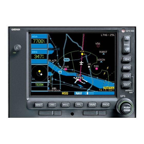
- Page 18 SECTION 1 INTRODUCTION Map Page After the GPS 500 acquires satellites and computes a position, the Map Page (Figure 1-13) appears automatically. Map Display Present Position Map Range Figure 1-13 Map Page The Map Page displays the present position (using an airplane symbol) relative to nearby airports, VORs, NDBs, intersections, user waypoints, and airspace boundaries.
- Page 19 (DTK), distance to waypoint (DIS), ground speed (GS), and estimated time enroute (ETE). See Section 14.3 for definitions of these navigation terms. GPS 500 Pilot’s Guide and Reference SECTION 1 INTRODUCTION Active Leg of Flight...
- Page 20 Continue to turn the small right knob until the desired airport is selected. Press the ENT Key to display the frequency list for the selected airport. GPS 500 Pilot’s Guide and Reference Departure, Enroute, or Arrival Airport Frequency List...
- Page 21 (when using approaches or STARs) or departure (when using SIDs) airport. Turn the small right knob to select the desired procedure and press the ENT Key. GPS 500 Pilot’s Guide and Reference SECTION 1 INTRODUCTION 1-13...
- Page 22 • Nearest Intersection Page • Nearest VOR Page • Nearest ARTCC Page • Nearest Airspace Page The communication frequencies and runway information may both be examined directly from the Nearest Airport Page. GPS 500 Pilot’s Guide and Reference 190-00181-60 Rev. G...
- Page 23 Figure 1-25 Airport Location Page To display runway and frequency information, press the small right knob to remove the cursor and turn the small right knob to display the desired information page. GPS 500 Pilot’s Guide and Reference SECTION 1 INTRODUCTION 1-15...
- Page 24 ‘Near airspace less than 2nm’ appears. • If the aircraft has entered an airspace, the message ‘Inside airspace’ appears. Figure 1-27 Nearest Airspace Page GPS 500 Pilot’s Guide and Reference 190-00181-60 Rev. G...
- Page 25 190-00181-60 Rev. G Flight Plans (FPL) The GPS 500 lets the pilot create up to 20 flight plans with up to 31 waypoints in each flight plan. Flight plans are created, edited, and activated using the FPL Key. The...
- Page 26 INTRODUCTION Since using flight plans is arguably one of the more complex features of the GPS 500, it will be discussed only briefly here, with focus on creating a new flight plan and activating it to use for navigation. Answers to additional questions about flight plans not found in this brief introduction can be found in Section 4, Flight Plans.
-
Page 27: Section 2: Nav Pages
Turn the small right knob to select the desired page (Figure 2-1). The bottom right corner of the screen is also used to display the GPS 500’ s turn advisories (‘Turn to 230°’) and NRST Group waypoint alerts (‘Next DTK 230°’) during flight plan and see Section 7 approach operations (Figure 2-2). -
Page 28: Nav
NAV/COM Satellite Status Figure 2-3 NAV Pages NOTE: *Six or Seven NAV pages are available when the GPS 500 installation includes connection to traffic and/or weather information sources. See Section 12 of this manual for more information. 2.3 DEFAULT NAV PAGE The first NAV page is the Default NAV Page (Figure 2-4). - Page 29 Quickly selecting the Default NAV Page from any page: Press and holding the CLR Key. NOTE: The GPS 500 always navigates TO a waypoint unless the OBS switch is set (preventing automatic waypoint sequencing), or if the aircraft has passed the last waypoint in the flight plan.
- Page 30 Turn the small right knob to display the list of available data items (Figure 2-6). Continue turning the small right knob to select the desired data item from the list. Figure 2-6 Select Field Type Window GPS 500 Pilot’s Guide and Reference 190-00181-60 Rev. G...
- Page 31 A ‘Crossfill?’ option is also provided for the Default NAV Page. This option transfers a direct-to destination or flight plan to a second Garmin 400 or 500 Series unit. See Section 8.2, Flight Planning Page: Crossfill for additional details on using the crossfill option.
-
Page 32: Map Page
Current Page Group Current Page Group Figure 2-9 Map Page NOTE: If the GPS 500 is unable to determine a GPS position, the present position (airplane) symbol does not appear on the Map Page. Different symbols are used to distinguish between waypoint types. - Page 33 Adding these data fields or changing the data types is outlined in Section 2.4. The five data fields can also be removed from the map to show a larger map image, as shown in Figure 2-9. GPS 500 Pilot’s Guide and Reference SECTION 2 NAV PAGES...
- Page 34 Press the ENT Key to display the Waypoint Information Page(s) for the selected waypoint (Figure 2-13). Figure 2-13 Information for On-Screen Waypoint Press the CLR Key to exit the information page(s). GPS 500 Pilot’s Guide and Reference 190-00181-60 Rev. G...
- Page 35 CLR Key to make the selection easier (Figure 2-15). Figure 2-15 Select Airspace with Target Pointer Press the ENT Key to display an options menu (Figure 2-16). Figure 2-16 Map Panning Options Window GPS 500 Pilot’s Guide and Reference SECTION 2 NAV PAGES...
- Page 36 Press the CLR Key to exit the Airspace Information Page. Map Setup Many of the GPS 500’ s functions are menu driven. Each of the main pages has an options menu, allowing customization of the corresponding page to the pilot’ s preferences and/or selection of special features which specifically relate to that page.
- Page 37 Press the ENT Key to accept the selected option. The automatic zoom feature automatically adjusts the map range from 2000 nm through each lower range, stopping at 1.0 nm when approaching the destination waypoint. GPS 500 Pilot’s Guide and Reference SECTION 2 NAV PAGES 2-11...
- Page 38 Turn the small right knob to select the maximum range at which the feature should appear on screen (or select ‘Off’ to never display the selected feature). Press the ENT Key to accept the selected option. GPS 500 Pilot’s Guide and Reference 190-00181-60 Rev. G...
- Page 39 To turn the data fields off/on: From the Map Page Menu, turn the large right knob to highlight ‘Data Fields On?’ (or ‘Data Fields Off?’) and press the ENT Key. GPS 500 Pilot’s Guide and Reference SECTION 2 NAV PAGES 2-13...
-
Page 40: Restoring The Factory Default Settings
Weather data and the ‘Clear Storm Data?’ option are only available when the GPS 500 installation includes connection to weather information sources. See the 400/500 Series Display Interfaces Pilot’ s Guide Addendum (190-00140-10) or Section 12 of this Pilot’... -
Page 41: Terrain Page
2.5 TERRAIN PAGE NOTE: GPS 500 units may* display either a TERRAIN Page or a TAWS Page, (but not both) depending upon the installed hardware and configuration. * Some earlier units are not equipped to support the TERRAIN and/or TAWS functionality, so therefore will not have a TERRAIN or TAWS page available. - Page 42 2-30) and press the ENT Key. Pressing the CLR Key when the TERRAIN Page is displayed can also be used to toggle aviation information on or off. Figure 2-30 TERRAIN Page Menu GPS 500 Pilot’s Guide and Reference 190-00181-60 Rev. G...
-
Page 43: Inhibit Mode
NOTE: If an obstacle and the projected flight path of the aircraft intersect, the display automatically zooms in to the closest potential point of impact on the TERRAIN Page. GPS 500 Pilot’s Guide and Reference SECTION 2 NAV PAGES Unlighted... -
Page 44: Taws Page
SECTION 2 NAV PAGES 2.6 TAWS PAGE NOTE: GPS 500 units may* display either a TERRAIN Page or a TAWS Page, (but not both) depending upon the installed hardware and configuration. * Some earlier units are not equipped to support the TERRAIN and/or TAWS functionality, so therefore will not have a TERRAIN or TAWS page available. - Page 45 Enabling TAWS: Select the TAWS Page and press the MENU Key. ‘Enable Terrain?’ is selected by default. Press the ENT Key. The TAWS system is functional again. GPS 500 Pilot’s Guide and Reference SECTION 2 NAV PAGES Annunciator Field 2-19...
- Page 46 SECTION 2 NAV PAGES TAWS Manual Test Garmin TAWS provides a manual test capability which verifies the proper operation of the aural and visual annunciations of the system prior to a flight. Manually testing the TAWS system: Select the TAWS Page and press the MENU Key.
-
Page 47: Nav/Com Page
Turn the small right knob to select the desired airport (Figure 2-43) and press the ENT Key. Figure 2-43 Airport Window Position of Current Page within Current Page Group GPS 500 Pilot’s Guide and Reference SECTION 2 NAV PAGES 2-21... - Page 48 (Figure 2-45). Figure 2-45 ‘Info’ Highlighted Press the ENT Key to display the restriction information (Figure 2-46). Figure 2-46 Restriction Information Page To return to the NAV/COM Page, press the ENT Key. GPS 500 Pilot’s Guide and Reference 190-00181-60 Rev. G...
-
Page 49: Satellite Status Page
(solid signal strength bar). Once the GPS receiver has determined the present position, the GPS 500 indicates position, track, and ground speed on the other navigation pages. The GPS receiver status field also displays the messages listed in Table 2-4 under the appropriate conditions: 190-00181-60 Rev. - Page 50 HUL is explained in Section 13. Searching Sky The GPS receiver is searching the sky for ANY visible satellites. The pilot is informed of this status with a ‘Searching the Sky’ message. Acquiring Sat The GPS receiver is acquiring satellites for navigation.
-
Page 51: Section 3: Direct-To Navigation
The GPS 500’ s direct-to function provides a quick method of setting a course to a destination waypoint. Once a direct-to is activated, the GPS 500 establishes a point-to- point course line (great circle) from the present position to the selected direct-to destination. Navigation data on the various NAV pages provides steering guidance until the direct-to is cancelled or replaced by a new destination. - Page 52 Use the small and large right knobs to enter the facility name or city location of the desired destination waypoint (Figure 3-6). When Facility Name spelling the facility name or city, the GPS 500’s and City Spell’N’Find™ feature selects the first entry Nearest Airport...
- Page 53 Continue turning the small right knob to scroll through the list and highlight the desired waypoint. Press the ENT Key to confirm the selected waypoint, and press the ENT Key again to activate the direct-to function. GPS 500 Pilot’s Guide and Reference SECTION 3 DIRECT-TO NAVIGATION...
- Page 54 If a single airport, NAVAID, or user waypoint is displayed on-screen (Figure 3-10): Figure 3-10 Single Waypoint Displayed a) Press the Direct-to Key b) Press the ENT Key twice. GPS 500 Pilot’s Guide and Reference 190-00181-60 Rev. G...
- Page 55 Figure 3-12 Panning Pointer Placed on Waypoint If the panning pointer is placed on an open location, press the Direct-to Key, then press the ENT Key twice to create a ‘+MAP’ waypoint and navigate to it. GPS 500 Pilot’s Guide and Reference SECTION 3 DIRECT-TO NAVIGATION...
- Page 56 GPS 500 resumes navigating the flight plan along the closest leg. Specifying a Course to a Waypoint When performing a direct-to, the GPS 500 sets a direct great circle course to the selected destination. The course to the destination can also be manually defined using the ‘CRS’...
-
Page 57: Section 4: Flight Plans
SECTION 4: FLIGHT PLANS The GPS 500 lets the pilot create up to 20 different flight plans, with up to 31 waypoints in each flight plan. The Flight Plan Page Group consists of two pages (Active Flight Plan Page and Flight Plan Catalog Page; Figures 4-1 and 4-2), accessed by pressing the FPL Key. - Page 58 Figure 4-6 Waypoint Identifier Field Selected Once all changes have been made, press the small right knob to return to the Flight Plan Catalog Page (Figure 4-7). Figure 4-7 Edited Flight Plan Page GPS 500 Pilot’s Guide and Reference 190-00181-60 Rev. G...
- Page 59 (Figure 4-9). Press the ENT Key when finished. Figure 4-9 Comment Line Selected Once all changes have been made, press the small right knob to return to the Flight Plan Catalog Page. GPS 500 Pilot’s Guide and Reference SECTION 4 FLIGHT PLANS...
- Page 60 Turn the large right knob to highlight ‘Invert & Activate FPL?’ (Figure 4-11) and press the ENT Key. The original flight plan remains intact in its flight plan catalog storage location. Figure 4-11 Flight Plan Catalog Page Menu GPS 500 Pilot’s Guide and Reference 190-00181-60 Rev. G...
- Page 61 Turn the large right knob to highlight ‘Delete Flight Plan?’ (Figure 4-13) and press the ENT Key. Figure 4-13 Flight Plan Catalog Page Menu With ‘Yes?’ highlighted, press the ENT Key to delete the flight plan. GPS 500 Pilot’s Guide and Reference SECTION 4 FLIGHT PLANS...
- Page 62 Transfer?’ (Figure 4-14) and press the ENT Key. Once ‘Initiate Transfer?’ is selected, a progress bar at the bottom of the page indicates the status of the crossfill transfer until completed. Figure 4-14 Crossfill Page GPS 500 Pilot’s Guide and Reference 190-00181-60 Rev. G...
-
Page 63: Deleting All Flight Plans
Select the ‘Sort List By Number?’ or ‘Sort List By Comment?’ option (whichever is currently displayed) from the Flight Plan Catalog Page Menu (Figure 4-17) and press the ENT Key. Figure 4-17 Flight Plan Catalog Page Menu GPS 500 Pilot’s Guide and Reference SECTION 4 FLIGHT PLANS... -
Page 64: Active Flight Plan Page
Accessing the Active Flight Plan Menu Page: Press the FPL Key to view the Active Flight Plan Page. Press the MENU Key (Figure 4-19). Figure 4-19 Active Flight Plan Page Menu GPS 500 Pilot’s Guide and Reference 190-00181-60 Rev. G... - Page 65 Activate Leg which is currently used for navigation guidance). Allows the pilot to transfer the active flight plan between two 400- or 500-series Garmin units Crossfill in a dual unit installation. See Section 8.2, Flight Planning: Crossfill for additional information on this feature.
- Page 66 Leg?’ option from the Active Flight Plan Page Menu (Figure 4-22) and press the ENT Key. Figure 4-22 Active Flight Plan Page Menu A confirmation window appears. With ‘Activate?’ highlighted, press the ENT Key. GPS 500 Pilot’s Guide and Reference 190-00181-60 Rev. G...
- Page 67 For precision approaches, a reminder window appears indicating that GPS guidance on such approaches is strictly for monitoring only. To confirm this reminder, highlight ‘Yes?’ and press the ENT Key. GPS 500 Pilot’s Guide and Reference SECTION 4 FLIGHT PLANS 4-11...
- Page 68 A second window appears listing available transitions for the departure. Turn the small right knob to highlight the desired transition waypoint and press the ENT Key. With ‘Load?’ highlighted, press the ENT Key. GPS 500 Pilot’s Guide and Reference 190-00181-60 Rev. G...
- Page 69 (Figure 4-31). Press the ENT Key to accept the waypoint. Figure 4-31 Closest Point of Flight Plan Window The GPS 500 displays the bearing (BRG) and distance (DIST) to the closest point along the flight plan, from the selected reference waypoint.
- Page 70 Identifiers appear in green text. Press the CLR Key to display a confirmation window (Figure 4-34). Figure 4-34 Remove Waypoint Window With ‘Yes?’ highlighted, press the ENT Key to remove the selected procedure. GPS 500 Pilot’s Guide and Reference 190-00181-60 Rev. G...
- Page 71 Turn the large right knob to highlight the procedure header (Figure 4-36). Figure 4-36 Procedure Header Highlighted Press the ENT Key to select the WPT Page Group. GPS 500 Pilot’s Guide and Reference SECTION 4 FLIGHT PLANS 4-15...
- Page 72 SECTION 4 FLIGHT PLANS Blank Page 4-16 GPS 500 Pilot’s Guide and Reference 190-00181-60 Rev. G...
-
Page 73: Section 5: Procedures
All available approaches are stored on the Jeppesen NavData card, and are automatically updated when the new card is inserted into the GPS 500. Subscription information for NavData cards is included in the GPS 500 package. - Page 74 Press the PROC Key to display the Procedures Page (Figure 5-5). Turn the large right knob to highlight ‘Activate Approach?’ (Figure 5-5) and press the ENT Key. Figure 5-5 Procedures Page GPS 500 Pilot’s Guide and Reference 190-00181-60 Rev. G...
-
Page 75: Non-Precision Approach Operations
(VOR, VOR/DME, NDB, RNAV, etc.) more accurately using GPS. Many overlay approaches are complex (in comparison to GPS-only approaches). The GPS 500 displays and provides guidance through each leg of the approach, automatically sequencing through each of these legs, up to the missed approach point (MAP). - Page 76 In some scenarios, it may be more convenient to immediately activate the approach and skip the ‘Load’ process outlined in the preceding step 3. The GPS 500 provides both options. Approaches with Procedure Turns The procedure turn portion of an approach is stored as one of the legs of the approach.
- Page 77 LYH VOR (the IAF). Also, select ‘Load?’ to load, but not activate, the approach. Figure 5-11 Approach and Transitions Windows Press the PROC Key, select ‘Activate Approach?’ and press the ENT Key to activate the approach. GPS 500 Pilot’s Guide and Reference SECTION 5 PROCEDURES...
- Page 78 Figure 5-12 Sample Approach with Procedure Turn Refer to Figure 5-12 for the following steps: Within 30 nm of the destination airport, the GPS 500 switches from ‘enroute’ mode to ‘terminal’ mode (as indicated in the lower left corner of the screen, Figure 5-13). The...
- Page 79 (Figure 5-18). Figure 5-18 Sequence to Inbound Leg Turn to the final approach course. Within 2.0 nm of the FAF (LYH), the GPS 500 switches from terminal mode to ‘approach’ mode (Figure 5-19). CDI scaling is tightened from 1.0 to 0.3 nm, full scale deflection.
- Page 80 Flying the Missed Approach After passing the MAP, if the runway isn’t in sight the pilot must execute a missed approach. The GPS 500 continues to give guidance along an extension of the final course segment (FAF to MAP) until the pilot manually initiates the missed approach procedure (as mentioned previously in reference to the ‘SUSP’...
- Page 81 Follow the missed approach procedures, as published on the approach plate, for proper climb and heading instructions. The GPS 500 guides the pilot to the holding pattern, along the 053° radial from LYH VOR. An alert message in the lower right-hand corner of the screen recommends entry procedures for the holding pattern (i.e., ‘HOLD DIRECT’, ‘HOLD...
- Page 82 The pilot may review the approach sequence by pressing the small right knob and turning the large right knob. Press the FPL Key to return to the navigation pages. Figure 5-26 Active Flight Plan Page GPS 500 Pilot’s Guide and Reference 190-00181-60 Rev. G...
- Page 83 Refer to Figure 5-27 for the following steps. As in the last example, within 30 nm of the airport, the GPS 500 switches from enroute to terminal mode, and the CDI scale transitions from 5.0 to 1.0 nm, full scale deflection.
- Page 84 (’NEXT DTK 209°’) appears along the bottom of the screen. 12) At 2.0 nm from the FAF (DEPOY intersection), the GPS 500 switches from terminal mode to approach mode. CDI scaling is tightened from 1.0 to 0.3 nm, full scale deflection.
- Page 85 NOTE: As this manual was being written, the letter/number DME arc names were being replaced with standard five-letter intersection names. Either naming convention may be used for an approach. GPS 500 Pilot’s Guide and Reference SECTION 5 PROCEDURES 5-13...
- Page 86 DO NOT USE FOR NAVIGATION Figure 5-34 Approach Window DO NOT USE FOR NAVIGATION Figure 5-35 Terminal Mode GPS 500 Pilot’s Guide and Reference Billard Muni (Topeka, KS) VOR or GPS Rwy 22 190-00181-60 Rev. G...
- Page 87 Refer to Figure 5-35 for the following steps. Within 30 nm of KTOP, the GPS 500 switches from enroute mode to terminal mode and the CDI scale transitions from 5.0 to 1.0 nm, full scale deflection. If the approach has not yet been activated (in step 2 above), do so when cleared for the approach (Figure 5-36).
- Page 88 Do not follow this extended course. Follow published missed approach procedures using the OBS Key to initiate the missed approach sequence, as outlined in ‘Flying the Missed Approach’ in this section. GPS 500 Pilot’s Guide and Reference 190-00181-60 Rev. G...
- Page 89 There are several ways to select ‘vectors to final’ with the GPS 500. The first two options below normally require the least workload to accomplish: • When the approach is first selected, choose ‘VECTORS’...
- Page 90 (refer to Figure 5-43 for the following steps): Within 30 nm of KTOP, the GPS 500 switches from enroute mode to terminal mode and the CDI scale transitions from 5.0 to 1.0 nm, full scale deflection.
- Page 91 1.0 to 0.3 nm, full scale deflection. Figure 5-47 Approach Mode When approaching the FAF, a waypoint alert (‘NEXT DTK 214°’) appears in the lower right corner. GPS 500 Pilot’s Guide and Reference SECTION 5 PROCEDURES ...
- Page 92 Certain approach, departure, and arrival procedures in the Jeppesen database contain course from fix flight plan legs. The GPS 500 is able to load these legs into the flight plan along with the rest of the procedure data, and provide navigation along these legs.
- Page 93 MAP. If a missed approach is required, use the OBS Key to initiate the missed approach sequence, as outlined below. Figure 5-52 ‘SUSP” Annunciation GPS 500 Pilot’s Guide and Reference SECTION 5 PROCEDURES 5-21...
- Page 94 OBS Key to release suspend mode and start the approach sequence, ‘SUSP’ re-appears above the OBS Key as the GPS 500 returns to suspend mode (Figure 5-54). This is normal when flying a course from fix to altitude leg and indicates that automatic leg sequencing is suspended.
- Page 95 Figure 5-56 Waypoint Alert 190-00181-60 Rev. G Note that the GPS 500 again displays ‘SUSP’ above the OBS Key. Automatic waypoint sequencing is suspended at the missed approach holding point. A waypoint alert (‘APPRCHING WPT’) appears along the bottom...
- Page 96 185°’) appears along the bottom of the screen (Figure 5-59) to provide guidance to the next waypoint (HFD VOR). The actual desired track (DTK) depends on ground speed and distance from HFD VOR. GPS 500 Pilot’s Guide and Reference Figure 5-58 Waypoint Alert 190-00181-60 Rev. G...
-
Page 97: Points To Remember For All Approaches
Figure 5-59 Waypoint Alert When the OBS Key is pressed, the GPS 500 automatically sequences to each waypoint along the remainder of the departure route, including the selected transition. 190-00181-60 Rev. G 5.3 POINTS TO REMEMBER FOR ALL APPROACHES • The GPS 500 is designed to complement printed approach plates and vastly improve situational awareness throughout the approach. - Page 98 SECTION 5 PROCEDURES Blank Page 5-26 GPS 500 Pilot’s Guide and Reference 190-00181-60 Rev. G...
-
Page 99: Section 6: Wpt Pages
SECTION 6: WPT PAGES 6.1 WPT PAGE GROUP Section 2.1 introduced the GPS 500’ s main page groups (Table 6-1)—NAV, WPT, AUX, NRST—and described each page in the NAV group. This second page group (WPT) provides information for the thousands of airports, VORs, NDBs, intersections, runways, frequencies, and procedures stored on the Jeppesen NavData card. - Page 100 Repeat steps 4 and 5 until the facility name or location is selected, then press the ENT Key . To remove the flashing cursor, press the small right knob. GPS 500 Pilot’s Guide and Reference 190-00181-60 Rev. G...
- Page 101 When entering an identifier, facility name, or location, the GPS 500’ s Spell’N’Find feature scrolls through the database, displaying those waypoints matching the characters that have been entered to that point.
-
Page 102: Airport Location Page
Airport Identifier, Symbol, and Type Field Elevation and Available Fuels Radar Coverage and Airspace Type Position of Current Page within Current Page Group Current Page Group Number of Pages in Current Page Group GPS 500 Pilot’s Guide and Reference 190-00181-60 Rev. G... - Page 103 Next FPL Apt?’ or ‘Select Destination Apt?’ and press the ENT Key (Figure 6-8). Figure 6-8 Airport Location Page Menu The Airport Location Page displays information regarding the next Flight Plan or Destination Airport. GPS 500 Pilot’s Guide and Reference SECTION 6 WPT PAGES...
-
Page 104: Airport Runway Page
Airport Runway Length and Width Page (Figure 6-11). Runway Surface Runway Lighting Figure 6-11 Airport Runway Page To remove the flashing cursor, press the small right knob. GPS 500 Pilot’s Guide and Reference 190-00181-60 Rev. G... - Page 105 Next FPL Apt?’ or ‘Select Destination Apt?’ and press the ENT Key (Figure 6-12). Figure 6-12 Airport Runway Page Menu The Airport Runway Page displays information regarding the next Flight Plan or Destination Airport. GPS 500 Pilot’s Guide and Reference SECTION 6 WPT PAGES...
-
Page 106: Airport Frequency Page
Figure 6-14 111.55 Highlighted Some listed frequencies may include designations for Frequency limited usage, as follows: • ‘TX’ - Transmit only • ‘RX’ - Receive only Scroll • ‘PT’ - Part time frequency GPS 500 Pilot’s Guide and Reference 190-00181-60 Rev. G... - Page 107 • Frequency - Communication frequencies which may include restrictions: Approach Class C Communication frequencies without restrictions: ATIS Center Control Multicom Ramp Unicom Navigation frequencies: GPS 500 Pilot’s Guide and Reference SECTION 6 WPT PAGES Arrival Class B Departure Terminal TRSA ASOS AWOS Clearance Gate...
-
Page 108: Airport Approach Page
(APR) procedure name field. Turn the small right knob to display a window of available approaches for the selected airport (Figure 6-19). Continue turning the small right knob to select the desired approach. GPS 500 Pilot’s Guide and Reference Approach Procedure Name Transitions: IAF’s, Feeder... - Page 109 • Select Destination Apt? - This option is only available when a Flight Plan is active. Allows the pilot to view the available approaches for the active flight plan destination airport. GPS 500 Pilot’s Guide and Reference SECTION 6 WPT PAGES 6-11...
-
Page 110: Airport Arrival Page
‘ARRIVAL’ procedure name field. Turn the small right knob to display a window of available arrivals for the selected airport (Figure 6-23). Continue turning the small right knob to select the desired arrival. GPS 500 Pilot’s Guide and Reference Arrival Procedure Name Transitions... - Page 111 Figure 6-25 Runway Window Press the ENT Key. To remove the flashing cursor, press the small right knob. GPS 500 Pilot’s Guide and Reference SECTION 6 WPT PAGES 6-13...
-
Page 112: Airport Departure Page
Scrolling through the available departures: Press the small right knob to activate the cursor. Turn the large right knob to place the cursor on the departure (DEP) procedure name field (Figure 6-27). GPS 500 Pilot’s Guide and Reference Departure Procedure Name Runway Associated with... - Page 113 FPL Key to return to the Airport Departure Page. To select any of the other options from the Airport Arrival Page Menu, follow the preceding steps, but select the desired option in step 3. GPS 500 Pilot’s Guide and Reference SECTION 6 WPT PAGES 6-15...
-
Page 114: Intersection Page
MGRS, or UTM/UPS • FREQ - Frequency in kilohertz (kHz) • Wx Brdcst - Weather information is broadcast on the selected facility’ s frequency GPS 500 Pilot’s Guide and Reference NDB Identifier Frequency and Weather and Symbol Broadcast Indication... -
Page 115: Vor Page
In addition to the airport, VOR, NDB, and intersection information contained in the Jeppesen NavData card, the GPS 500 allows the pilot to store up to 1,000 user- defined waypoints. The User Waypoint Page (Figure 6-34) displays the waypoint name (up to five characters... - Page 116 Use the small and large right knobs to enter a name for the new waypoint and press the ENT Key. Turn the large right knob to highlight the first reference waypoint (REF WPT) field (Figure 6- 37). GPS 500 Pilot’s Guide and Reference 190-00181-60 Rev. G...
- Page 117 VOR. However, the pilot can select any waypoint by identifier to use as a reference in this field. The GPS 500 can store user-defined waypoints which are generated from other equipment in the panel. For example,...
- Page 118 Figure 6-40 Position Field Selected The cursor moves to the ‘Modify?’ action field. Press the ENT Key to modify the waypoint. Press the small right knob to remove the flashing cursor. GPS 500 Pilot’s Guide and Reference 190-00181-60 Rev. G...
- Page 119 ‘from’ or ‘to’ waypoint in the active flight plan, the GPS 500 alerts the pilot with the ‘Can’t change an active waypoint’ or ‘Waypoint is active and can’t be deleted’ message. The...
- Page 120 ENT Key. Figure 6-43 User Waypoint Page Menu Press the CLR Key to display a ‘delete waypoint’ confirmation window. With ‘Yes?’ highlighted, press the ENT Key to delete the selected user waypoint. GPS 500 Pilot’s Guide and Reference 190-00181-60 Rev. G...
- Page 121 Figure 6-45 User Waypoint Name Selected A ‘rename waypoint’ confirmation window is displayed (Figure 6-46). With ‘Yes?’ highlighted, press the ENT Key to rename the selected user waypoint. Figure 6-46 Rename Waypoint Window GPS 500 Pilot’s Guide and Reference SECTION 6 WPT PAGES 6-23...
- Page 122 ENT Key. A ‘delete all waypoints’ confirmation window is displayed (Figure 6-49). With ‘Yes?’ highlighted, press the ENT Key to delete all user waypoints from memory. Figure 6-49 Delete All Waypoints Window GPS 500 Pilot’s Guide and Reference 190-00181-60 Rev. G...
-
Page 123: Section 7: Nrst Pages
From any page, press the NRST Key, ‘NRST’ appears along the bottom of the screen (see Figure 7-2). Figure 7-2 Nearest Airport Page Turn the small right knob to select the desired NRST page. NRST VOR GPS 500 Pilot’s Guide and Reference SECTION 7 NRST PAGES... - Page 124 Press the small right knob to activate the cursor. Turn the small right knob to scroll through the list (Figure 7-4). Figure 7-4 Nearest ARTCC Page Press the small right knob to remove the flashing cursor. Scroll GPS 500 Pilot’s Guide and Reference 190-00181-60 Rev. G...
-
Page 125: Nearest Airport Page
The pilot may wish to use this feature to exclude seaplane bases or runway lengths which would be difficult or impossible to land upon. See Section 8.5, Setup Page: Nearest Airport Criteria for additional details. GPS 500 Pilot’s Guide and Reference SECTION 7 NRST PAGES Best Available... - Page 126 Figure 7-8 Additional WPT Page To return to the Nearest Airport Page, verify that ‘Done?’ is highlighted by the flashing cursor and press the ENT Key (or press the CLR Key). GPS 500 Pilot’s Guide and Reference 190-00181-60 Rev. G...
-
Page 127: Nearest Intersection Page
Bearing To and Distance To Intersection Identifier and Symbol Scroll Position of Current Page within Current Page Group GPS 500 Pilot’s Guide and Reference SECTION 7 NRST PAGES Bearing To and Distance To Frequency Scroll Current Number of Pages in... -
Page 128: Nearest Vor Page
To return to the Nearest VOR Page, verify that ‘Done?’ is highlighted by the flashing cursor and press the ENT Key (or press the CLR Key). Press the small right knob to remove the flashing cursor. GPS 500 Pilot’s Guide and Reference 190-00181-60 Rev. G... -
Page 129: Nearest User Waypoint Page
Press the small right knob to activate the cursor (Figure 7-14). Turn the small right knob to scroll through the list. Press the small right knob to remove the flashing cursor. GPS 500 Pilot’s Guide and Reference SECTION 7 NRST PAGES Bearing To and Distance To Current... -
Page 130: Nearest Flight Service Station (Fss) Page
‘Near airspace less than 2nm’ appears (Figure 7-17). The Nearest Airspace Page shows the airspace as ‘Ahead < 2nm’. GPS 500 Pilot’s Guide and Reference 190-00181-60 Rev. G... - Page 131 Section 7.1. Press the small right knob to activate the cursor. Turn the large right knob to scroll through the list, highlighting the desired airspace. GPS 500 Pilot’s Guide and Reference SECTION 7 NRST PAGES Position of Current Page...
- Page 132 To return to the Nearest Airspace Page, turn the large right knob to highlight ‘Done?’ and press the ENT Key (or press the CLR Key). Press the small right knob to remove the flashing cursor. GPS 500 Pilot’s Guide and Reference 190-00181-60 Rev. G...
- Page 133 Page to provide an extra margin of safety above/below the published limits (Section 8.4, Setup Page: Airspace Alarms for additional details). Figure 7-21 Airspace Page for MOA GPS 500 Pilot’s Guide and Reference SECTION 7 NRST PAGES • Unlimited • Surface...
- Page 134 SECTION 7 NRST PAGES Blank Page 7-12 GPS 500 Pilot’s Guide and Reference 190-00181-60 Rev. G...
-
Page 135: Section 8: Aux Pages
SECTION 8: AUX PAGES 8.1 AUX PAGE GROUP Section 2.1 introduced the GPS 500’ s main page groups (Table 8-1)—NAV, WPT, AUX, NRST—and described each page in the NAV group. The third page group (AUX) allows the pilot to change unit settings. The... -
Page 136: Flight Planning Page
(via ‘menu options’) to E6B functions for fuel planning, trip planning, density altitude/true airspeed/winds aloft calculations, and a ‘Crossfill’ function to transfer flight plans/user waypoints to a second 400/500-series Garmin unit. When a menu option is selected, the corresponding page appears providing additional information and features. - Page 137 One-time, periodic, and event-based messages are allowed. One-time messages appear once the timer expires and reappear each time the GPS 500 is powered on, until the message is deleted. Periodic messages automatically reset to the original timer value, once the message is displayed.
- Page 138 Page Menu for the other mode, then press the ENT Key to accept the other mode. NOTE: The ‘Change Fields?’ option above is only available on GPS 500 installations which include a Shadin fuel computer. In these installations, use the ‘Change Fields?’ option to review separate fuel information for left and right engines.
- Page 139 (Figure 8-15) and turn the small right knob to select the desired leg of the flight plan, or select ‘Cum’ to apply trip planning calculations to the entire flight plan. GPS 500 Pilot’s Guide and Reference SECTION 8 AUX PAGES...
- Page 140 The flashing cursor moves to the barometric pressure (BARO) field. Use the small and large right knobs to enter the barometric pressure (altimeter setting). Press the ENT Key when finished. GPS 500 Pilot’s Guide and Reference 190-00181-60 Rev. G...
- Page 141 Use the small and large right knobs to enter the message text. Press the ENT Key when finished. (The GPS 500 stores up to nine scheduled messages holding 20 characters each.) The flashing cursor moves to the type field under the new message.
- Page 142 If either of the messages ‘data transfer error’ or ‘data transfer cancelled’ are received during an automatic or manual transfer, the pilot must force another transfer. GPS 500 Pilot’s Guide and Reference 190-00181-60 Rev. G...
- Page 143 (Figure 8-14). Figure 8-14 Transfer Window • Active Flight Plan - Transfer the active flight plan to/from a second 400/500-series Garmin unit in a dual unit installation. This option is the default when selecting ‘Crossfill’ from the Active Flight Plan Page.
-
Page 144: Utility Page
Menu Options (to Select, Highlight with Cursor and Press the ENT Key) Position of Current Page within Current Page Group Current Page Group GPS 500 Pilot’s Guide and Reference Number of Pages in Current Page Group Figure 8-15 Utility Page 190-00181-60 Rev. G... - Page 145 Departure and total trip time recording can be configured to run either any time GPS 500 power is on, or only when ground speed exceeds 30 knots. • Trip Statistics - Provides readouts for trip odometers, average speed, and maximum speed.
- Page 146 If a ‘WARN’ annunciation appears at the bottom left corner, GPS satellite coverage may be sufficient, but the GPS 500 has detected a position error which exceeds protection limits. In this condition, all GPS navigation data on the GPS 500 is disabled.
- Page 147 ENT Key. With ‘Yes?’ highlighted on the confirmation window (figure 8-19), press the ENT Key to remove the checklist or all checklists from memory. Figure 8-19 Delete Checklist Confirmation Window GPS 500 Pilot’s Guide and Reference SECTION 8 AUX PAGES 8-13...
- Page 148 For a count down timer, turn the large right knob to highlight the time field. Use the small and large right knobs to enter the count down time—in hours, minutes, and seconds. Press the ENT Key when finished. GPS 500 Pilot’s Guide and Reference 190-00181-60 Rev. G...
- Page 149 ‘Pwr-on’ or ‘GS>30kt’. Turn the small right knob to select the desired reset mode (Figure 8-21). ‘Pwr-on’ records a departure time when the GPS 500 is turned on. ‘GS>30kt’ records a departure time once the GPS-computed ground speed exceeds 30 knots.
- Page 150 The flashing cursor moves to the arrival time field. Use the small and large right knobs to enter the time for which the pilot wants to determine RAIM availability. Press the ENT Key when finished. GPS 500 Pilot’s Guide and Reference 190-00181-60 Rev. G...
- Page 151 The flashing cursor moves to ‘Compute RAIM?’ (Figure 8-24). Press the ENT Key to begin RAIM prediction. Once calculations are complete, the GPS 500 displays one of the following in the RAIM status field: Figure 8-24 ‘Compute RAIM?’ Highlighted •...
-
Page 152: Setup Page
Menu Options (to Select, Highlight with Cursor and Press the ENT Key) Position of Current Page within Current Page Group Current Page Group GPS 500 Pilot’s Guide and Reference Number of Pages in Current Page Group Figure 8-28 Setup Page 190-00181-60 Rev. G... - Page 153 For example, if 1.0 nm is selected, the GPS 500 uses this for the enroute and terminal phase and ramp down to 0.3 nm during an approach. Note that the Receiver Autonomous...
- Page 154 Configuration settings for position format are also provided, and the map datum setting is shown. The map datum used in the GPS 500 is WGS 84. Note that a map datum that does not match the charts can result in significant differences in position information.
- Page 155 Available data options are a configurable data field (to display information such as ground speed, track, or distance to destination), or if the GPS 500 is interfaced with a traffic information device (see Section 12), thumbnail traffic can be configured for display in the data field.
- Page 156 The ‘System CDI’ field displays the CDI scale currently in use. The ‘System CDI’ setting may differ from the ‘Selected CDI’ depending upon the current phase of flight (as described previously in this section). GPS 500 Pilot’s Guide and Reference 190-00181-60 Rev. G...
- Page 157 (to the immediate right of ‘User’). Use the small and large right knobs to enter the desired magnetic variation direction and value. Press the ENT Key when finished. GPS 500 Pilot’s Guide and Reference SECTION 8 AUX PAGES 8-23...
- Page 158 • MGRS - Military Grid Reference System • UTM/UPS - Universal Transverse Mercator/ Universal Polar Stereographic grids Press the ENT Key to accept the selected format. GPS 500 Pilot’s Guide and Reference 190-00181-60 Rev. G...
- Page 159 Local 24hr, or UTC (Figure 8-39). Figure 8-39 Time Format Window Continue turning the small right knob to select the desired time format. Press the ENT Key to accept the selection. GPS 500 Pilot’s Guide and Reference SECTION 8 AUX PAGES 8-25...
- Page 160 If ‘Manual’ is selected, the flashing cursor moves to the backlight level field. Turn the small right knob to select the desired level. Press the ENT Key to accept the selection. GPS 500 Pilot’s Guide and Reference 190-00181-60 Rev. G...
- Page 161 • Configurable Data Fields - Displays a user-select- able data field of navigation data (see Table 8-3 for available options). • Traffic Watch - If the GPS 500 is connected to other equipment providing traffic alert informa- tion, a window is provided to display traffic information.
- Page 162 Setup Page, using the steps described at the beginning of this section. Press the MENU Key to display the CDI/Alarms Page Menu (Figure 8-44). Figure 8-44 CDI/Alarms Page Menu With ‘Restore Defaults?’ highlighted, press the ENT Key. GPS 500 Pilot’s Guide and Reference 190-00181-60 Rev. G...
-
Page 163: Section 9: Vertical Navigation (Vnav)
SECTION 9: VERTICAL NAVIGATION (VNAV) The GPS 500’ s Vertical Navigation Page (Figure 9-2) allows you to create a three-dimensional profile (Figure 9-1) which guides you from your present position and altitude to a final (target) altitude at a specified location. - Page 164 To change the rate, turn the large right knob to highlight the “VS Profile” field and use the small and large right knobs to enter a new rate. Press the ENT Key when finished. GPS 500 Pilot’s Guide and Reference 190-00181-60 Rev. G...
- Page 165 “Approaching Target Altitude” message is provided (Figure 9-6). The VSR readout on the Default NAV and Map Pages is blanked out, at this point. Figure 9-6 Target Altitude Message GPS 500 Pilot’s Guide and Reference SECTION 9 VERTICAL NAVIGATION...
- Page 166 Press the MENU Key to display the Verti- cal Navigation Page Options menu (Figure 9-8). Figure 9-8 VNAV Page Options Menu Turn the large right knob to highlight “Restore Defaults?” and press the ENT Key. GPS 500 Pilot’s Guide and Reference 190-00181-60 Rev. G...
-
Page 167: Section 10: Terrain
GPS 500 units to increase situational awareness and aid in reducing controlled flight into terrain (CFIT). TERRAIN functionality is a standard feature found in GPS 500 units with main software version 6.01 or above, along with appropriate hardware upgrades. - Page 168 During power-up, the terrain/obstacle database versions are displayed along with a disclaimer to the pilot. At the same time, TERRAIN self-test begins. A test failure is annunciated for TERRAIN as shown in Table 10-4. GPS 500 Pilot’s Guide and Reference 190-00181-60 Rev. G...
-
Page 169: Terrain Page
Points Obstacle above or within 100’ below current aircraft altitude Obstacle between 100’ and 1000’ below current aircraft altitude GPS 500 Pilot’s Guide and Reference SECTION 10 TERRAIN Potential Impact Point Terrain above or within 100 ft below the aircraft... -
Page 170: Terrain Alerts
• Press the ENT Key. This acknowledges the pop-up alert and accesses the TERRAIN Page. Figure 10-3 TERRAIN Advisory Pop-up Figure 10-4 TERRAIN Caution Pop-up (Flashing) GPS 500 Pilot’s Guide and Reference 190-00181-60 Rev. G... - Page 171 Imminent Obstacle Impact (IOI) Advisory Imminent Obstacle Impact (IOI) Caution Premature Descent Alert (PDA) 190-00181-60 Rev. G Annunciation (FLASHING) (FLASHING) (FLASHING) (FLASHING) Table 10-2 TERRAIN Alert Summary GPS 500 Pilot’s Guide and Reference SECTION 10 TERRAIN Pop-Up Alert None None None (FLASHING) (FLASHING) (FLASHING)
- Page 172 Table 10-4 Minimum Terrain and Obstacle Clearance Values for FLTA Alerts 10-6 TERRAIN Page Annunciation None Table 10-3 Additional System Annunciations Minimum Clearance Minimum Clearance Altitude Level Flight (ft) Altitude Descending (ft) GPS 500 Pilot’s Guide and Reference Pop-Up Alert None None None None None 190-00181-60 Rev. G...
- Page 173 Select the TERRAIN Page and press the MENU Key. ‘Enable Terrain?’ is selected by default. Press the ENT Key. The TERRAIN system is functional again. GPS 500 Pilot’s Guide and Reference SECTION 10 TERRAIN Figure 10-6 TERRAIN Page Menu Annunciator Field...
- Page 174 If the terrain/obstacle database is not available, ‘TER FAIL’ is generated in the annunciation window, and ‘TERRAIN FAILED’ is generated on the TERRAIN Page (Figure 10-9). Figure 10-9: TERRAIN FAILED Display GPS 500 Pilot’s Guide and Reference 190-00181-60 Rev. G...
-
Page 175: Database Information For Terrain
General Database Information Garmin TERRAIN uses terrain and obstacle information supplied by government sources. The data undergoes verification by Garmin to confirm accuracy of the content, per TSO-C151b. However, the displayed information should never be understood as being all- inclusive. Pilots must familiarize themselves with the appropriate sectional charts for safe flight. - Page 176 (compare database cycle numbers to determine if a newer version is available). Updated terrain data cards may be obtained by calling Garmin at one of the numbers listed in the front of this document. Updating terrain/obstacle databases: Acquire a new terrain data card from Garmin.
-
Page 177: Section 11: Taws
(FAR Parts 91.223, 135.154). TAWS functionality is an available feature found in GPS 500 TAWS units with main software version 6.01 or above, along with appropriate hardware upgrades. TAWS provides visual and aural annunciations when terrain and obstacles are within the given altitude threshold from the aircraft. - Page 178 TAWS self-test begins. One of the following aural messages is generated: • “TAWS System Test OK” • “TAWS System Failure” A test failure is also annunciated for TAWS as shown in Table 11-4. GPS 500 Pilot’s Guide and Reference 190-00181-60 Rev. G...
-
Page 179: Taws Page
Points Obstacle above or within 100’ below current aircraft altitude Obstacle between 100’ and 1000’ below current aircraft altitude GPS 500 Pilot’s Guide and Reference SECTION 11 TAWS Potential Impact Point Terrain above or within 100 ft below the aircraft... -
Page 180: Taws Alerts
11-2) are configurable at installation and are installation-dependent. NOTE: TAWS Caution Alerts are displayed as constant black text on a yellow background; TAWS Warning Alerts are displayed as constant white text on a red background. GPS 500 Pilot’s Guide and Reference 190-00181-60 Rev. G... - Page 181 Terrain Ahead, Pull Up; Terrain Ahead, Pull Up’* “Obstacle Ahead, Pull Up; Obstacle Ahead, Pull Up” “Obstacle Ahead, Pull Up; Obstacle Ahead, Pull Up”* None Table 11-2 TAWS Alerts Summary GPS 500 Pilot’s Guide and Reference SECTION 11 TAWS Aural Message “Pull Up”...
- Page 182 None Table 11-3 Additional System Annunciations Minimum Clearance Minimum Clearance Altitude Level Flight (ft) Altitude Descending (ft) GPS 500 Pilot’s Guide and Reference Aural Message “TAWS System Failure” None “TAWS Not Available” “TAWS Available” is generated when sufficient GPS signal is re-established.
- Page 183 Select the TAWS Page and press the MENU Key. ‘Enable Terrain?’ is selected by default. Press the ENT Key. The TAWS system is functional again. GPS 500 Pilot’s Guide and Reference SECTION 11 TAWS Figure 11-6 TAWS Page Menu Annunciator Field...
- Page 184 5500 5000 4500 4000 3500 3000 2500 2000 1500 1000 Figure 11-8 Excessive Descent Rate Alert Criteria 11-8 "PULL UP" "PULL UP" 2000 4000 6000 8000 10000 Descent Rate (FPM) GPS 500 Pilot’s Guide and Reference 12000 190-00181-60 Rev. G...
- Page 185 Figure 11-9 Negative Climb Rate (NCR) Alert Criteria 190-00181-60 Rev. G “DON’T SINK” “DON’T SINK” Altitude Loss (Feet) “DON’T SINK” “DON’T SINK” 1000 1500 2000 2500 3000 Sink Rate (Feet Per Minute) GPS 500 Pilot’s Guide and Reference SECTION 11 TAWS 3500 4000 11-9...
- Page 186 If the terrain/obstacle database is not available, the aural message “TAWS System Failure” is generated along with ‘TER FAIL’ in the annunciation window, and ‘TERRAIN FAILED’ on the TAWS Page (Figure 11-11). Figure 11-11: TAWS FAILED Display GPS 500 Pilot’s Guide and Reference 190-00181-60 Rev. G...
-
Page 187: Database Information For Taws
General Database Information Garmin TAWS uses terrain and obstacle information supplied by government sources. The data undergoes verification by Garmin to confirm accuracy of the content, per TSO-C151b. However, the displayed information should never be understood as being all-inclusive. Pilots must familiarize themselves with the appropriate sectional charts for safe flight. - Page 188 (compare database cycle numbers to determine if a newer version is available). Updated terrain data cards may be obtained by calling Garmin at one of the numbers listed in the front of this document. Updating terrain/obstacle databases: Acquire a new terrain data card from Garmin.
-
Page 189: Section 12: Additional Features
TIS Traffic display is available to aircraft equipped with a Mode S Data Link, such as the Garmin GTX 330 Transponder. TIS traffic information from a GTX 330 Transponder can then be displayed on a 500 Series unit. - Page 190 The user should not start evasive maneuvers using information from the GPS 500 display or on a traffic advisory only. The display and advisories are intended only for assistance in visually locating the traffic, due to the lack in resolution and coordination ability.
- Page 191 Report, a postage-paid card designed for this purpose. These cards may be obtained at FAA FSS’ s , General Aviation District Offices, Flight Standards District Offices, and General Aviation Fixed Based Operations. GPS 500 Pilot’s Guide and Reference SECTION 12 ADDITIONAL FEATURES 12-3...
- Page 192 Traffic Advisory (TA) Symbol ‘Own’ (Client) Aircraft Symbol Out-of-Range Traffic Advisory (TA) Symbol Figure 12-3 Out-of Range TA Symbol GPS 500 Pilot’s Guide and Reference Symbol ‘Other’ (Intruder) Traffic Ground Traffic Symbol Track Vector Figure 12-2 Traffic Page 190-00181-60 Rev. G...
-
Page 193: Traffic Page
If it is not available, the Traffic Page is a track-up display. It is labeled on the upper portion of the Traffic Page. Figure 12-5 Traffic Page GPS 500 Pilot’s Guide and Reference SECTION 12 ADDITIONAL FEATURES Heading or Track... - Page 194 • OPER - When the Traffic Page displays OPER in the upper right hand corner of the display (Figure 12-11), the TIS system is in operational mode and available to display traffic on the Traffic or Map Page. GPS 500 Pilot’s Guide and Reference 190-00181-60 Rev. G...
- Page 195 Figure 12-13 Traffic Warning Window Indicator NOTE: The Traffic Warning Window is disabled when the aircraft ground speed is less than 30 knots or when an approach is active. GPS 500 Pilot’s Guide and Reference SECTION 12 ADDITIONAL FEATURES 12-7...
- Page 196 Traffic Page. When a Traffic Advisory is active, the Traffic Banner is displayed in the lower right corner of the Map Page. Non- Bearing Traffic Advisory Banner Figure 12-15 Map Page Displaying Traffic GPS 500 Pilot’s Guide and Reference Traffic Advisory Banner 190-00181-60 Rev. G...
- Page 197 Select ‘TRFC’ from the Select Field Type List and press the ENT Key. Note that the thumbnail range defaults to 6 nm and cannot be changed (Figure 12-17). Figure 12-17 Thumbnail Traffic on Map Page GPS 500 Pilot’s Guide and Reference SECTION 12 ADDITIONAL FEATURES 12-9...
- Page 198 Table 12-3 Power-up Messages NOTE: ‘NO DATA’ may be a normal mode of operation in a dual transponder installation where the GTX 330 with TIS is not the selected transponder. GPS 500 Pilot’s Guide and Reference Description 190-00181-60 Rev. G...
- Page 199 The 500 Series unit displays ‘STBY’. As described previously, both the standby and operating modes can be manually overridden by the display controls. GPS 500 Pilot’s Guide and Reference SECTION 12 ADDITIONAL FEATURES 12-11...
-
Page 200: Gts 8Xx Traffic Systems
12.2 GTS 8XX TRAFFIC SySTEMS Introduction All information in this section pertains to the display and control of the Garmin GPS 500/GTS 8XX interface, refer to the 400/500 Series Display Interfaces Pilot’ s Guide Addendum (190-00140-10) when interfacing with non-Garmin products... - Page 201 TA threats. Traffic Symbology Traffic information from the GTS 8XX is displayed on the GPS 500 unit using TAS/TCAS symbology (Table 12-4) on a dedicated Traffic page, and on the moving Map Page. The displayed traffic information generally includes the relative range, bearing, and altitude of intruder aircraft.
- Page 202 From the Traffic Page, press the MENU Key to display the Page Menu. Turn the small right knob to select ‘Self Test?’. Press the ENT Key. Figure 12-21 Self-Test Mode GPS 500 Pilot’s Guide and Reference Test-Mode Indication 190-00181-60 Rev. G...
- Page 203 • 2 and 6 nm • 6 and 12 nm • 12 and 24 nm (GTS 820/850 only) • 24 and 40 nm (GTS 820/850 only) GPS 500 Pilot’s Guide and Reference SECTION 12 ADDITIONAL FEATURES Orientation Source Operating Mode...
- Page 204 Figure 12-24 “UNR” Selected Press the small right knob to turn the cursor off after the selection is made. Drawing Not to Scale Figure 12-23 Altitude Display Modes GPS 500 Pilot’s Guide and Reference +9,000 ft +2,700 ft 0 ft -2,700 ft...
- Page 205 Turn the large right knob to select the desired Advisory Banner Traffic Mode option. Turn the small right knob to select the desired option Press the ENT Key. Repeat steps 7-9 for Traffic Symbol and Traffic Label. GPS 500 Pilot’s Guide and Reference SECTION 12 ADDITIONAL FEATURES 12-17...
- Page 206 When the target pointer is placed on traffic, the traffic range and altitude deviation are displayed (Figure 12-29). The traffic is identified as: • TA: Traffic Advisory • PA: Proximity Advisory GPS 500 Pilot’s Guide and Reference • TRFC: Other Traffic 190-00181-60 Rev. G...
-
Page 207: Weather Data Link Interface
Pilot’s Guide Addendum (190-00140-10) when interfacing with non-Garmin products. Introduction GPS 500 units can interface with the GDL 49 or the GDL 69/69A. The GPS 500 unit provides the display and control interface for the textual and graphical weather data link. - Page 208 The displayed NEXRAD data will reflect the highest intensity level sampled within a 2 x 2 km (4 sq km) unit of area (depending on available system memory). GPS 500 Pilot’s Guide and Reference 190-00181-60 Rev. G...
-
Page 209: Nexrad Intensity
>1 or sleet Heavy >1 or sleet Heavy sleet Intense sleet Extreme Extreme Extreme Table 12-6 NEXRAD Intensity Colors GPS 500 Pilot’s Guide and Reference SECTION 12 ADDITIONAL FEATURES Snow Sleet Hail Very Light Light Light Light Light Light – Medium... - Page 210 Posn’-Position is current, ‘Look Ahead’-Position is look ahead position. ‘From ID’-Position is from the ID entered into the WPT field. ‘Flight Plan’ is the ID selected from the active flight plan. GPS 500 Pilot’s Guide and Reference 190-00181-60 Rev. G...
- Page 211 (MSG) flashes to alert the pilot to one of the following messages depending on the type of data received: • New NEXRAD Received • New Graphic METAR Received • New Text METAR Received GPS 500 Pilot’s Guide and Reference SECTION 12 ADDITIONAL FEATURES 12-23...
- Page 212 Request Pages, depending on which is currently displayed on the Weather Page. • Display Legend? - This option is a link to the Weather Legend Page. See the Weather Legend Page paragraph following in this section. GPS 500 Pilot’s Guide and Reference 190-00181-60 Rev. G...
- Page 213 Weather Page. For example, if the pilot selects ‘Low’ NEXRAD Density, both the Weather Page and the Map Page display the NEXRAD graphics in the ‘Low’ mode. GPS 500 Pilot’s Guide and Reference SECTION 12 ADDITIONAL FEATURES Pattern Color...
- Page 214 ‘Request NEXRAD?’ and ‘Request METAR?’ options select the NEXRAD and METAR Request Pages, respectively. ‘View Text METAR?’ selects the Textual METAR Page for the desired airport, if textual METAR is available for that airport. GPS 500 Pilot’s Guide and Reference 190-00181-60 Rev. G...
- Page 215 Distance - The distance from the nearest VOR. • Radial - The radial from the nearest VOR. • Position - Displays the aircraft’s current position expressed in Latitude and Longitude. GPS 500 Pilot’s Guide and Reference SECTION 12 ADDITIONAL FEATURES 12-27...
- Page 216 Turn the small right knob and highlight ‘Metar Request’ (Figure 12-41). Figure 12-41 Data Link Page Press the ENT Key. The ‘METAR REQUEST’ Page is displayed (Figure 12-42). Figure 12-42 Metar Request Page GPS 500 Pilot’s Guide and Reference 190-00181-60 Rev. G...
- Page 217 ENT Key does not send the request until after the auto time period. To exit from the NEXRAD Request Page, press the small right knob. The Data Link Page is displayed. GPS 500 Pilot’s Guide and Reference SECTION 12 ADDITIONAL FEATURES 12-29...
- Page 218 Graphical METAR data is displayed for that airport in a thumbnail image. NOTE: For the GDL 69/69A, METAR data is automatically updated every twelve minutes from the time of initial request. The request has GPS 500 Pilot’s Guide and Reference 190-00181-60 Rev. G...
- Page 219 • Winds • Wind Gust For Temperature/Dewpoint Data: • Age of Data in Minutes • Temperature/Dewpoint Displaying Textual METARS Once received, textual METARS are displayed on the METARS Text Page. GPS 500 Pilot’s Guide and Reference SECTION 12 ADDITIONAL FEATURES 12-31...
- Page 220 Press the small right knob. The Temperature/ Dewpoints are displayed on the NAV Weather Page. NOTE: See a complete description of all METAR, Wind, and Temp-Dewpoint symbols at the end of this section. GPS 500 Pilot’s Guide and Reference 190-00181-60 Rev. G...
-
Page 221: Troubleshooting
GDL 49’ s receive queue waiting to be sent to the 500 Series unit. • Sat ID/Connectivity - Shows the current satellite in view and also indicates the status of the current satellite connection. See Table 12-8. GPS 500 Pilot’s Guide and Reference SECTION 12 ADDITIONAL FEATURES 12-33... - Page 222 ‘X2’, or Satellite signal quality is indicated by the ‘X3’ numbers 0, 1, 2, or 3; where 0=none, 1=poor, 2=good, and 3=excellent. Table 12-10 Sat ID Field GPS 500 Pilot’s Guide and Reference SAT ID FIELD DESCRIPTION 190-00181-60 Rev. G...
- Page 223 RA – Rain SCT – Scattered clouds SM – Statue Miles TEMPO – Occasionally TS – Thunderstorm Table 12-12 Forecast Abbreviations GPS 500 Pilot’s Guide and Reference SECTION 12 ADDITIONAL FEATURES ‘-’ – (Light) (xxxx are numbers) BKN – Broken clouds BR –...
- Page 224 KMWM is marginal VFR, with heavy snow and low IFR minutes (Yellow) visibility. The data age is 31-60 minutes old. (Yellow) Data Age Heavy (Green) (Yellow) GPS 500 Pilot’s Guide and Reference Marginal Low IFR Precipitation Ceiling Visibility Station Identifier Figure 12-47 METAR Symbol 190-00181-60 Rev. G...
- Page 225 25 knots, gusting to 36 knots or greater. The data age is 11-20 minutes old. Gust Offset Unknown 5 kts 10 kts ≥ 37 kts Wind Vector Figure 12-48 Wind Symbol GPS 500 Pilot’s Guide and Reference SECTION 12 ADDITIONAL FEATURES Wind Speed Data Age 12-37...
- Page 226 This symbol in Figure 12-49 displays the difference between the reported temperature and dewpoint as 6-10 degrees Fahrenheit at KSPW. Temperature Dewpoint Figure 12-49 Temp-Dewpoint Symbol 12-38 Unknown 11°+ (Green) 7° - 10° (Green) 0° - 6° (Yellow) GPS 500 Pilot’s Guide and Reference 190-00181-60 Rev. G...
-
Page 227: Section 13: Fault Detection & Exclusion
‘GPS as a Primary Means of Navigation for Oceanic/Remote Operations’ per FAA Notice N8110.60. The oceanic flight phase is used by the GPS 500 when the aircraft is more than 200 nm from the nearest airport. FDE requires no pilot interaction during flight, but predicting the capability of the GPS constellation to provide service during a flight is done by the pilot prior to departure. -
Page 228: Pre-Departure Verification Of Fde
The trainer software and the document ‘400/500 Series FDE Prediction Instructions’ (190-00643-00) are available on Garmin’ s website (www.garmin.com) for free download. 13-2 Figure 13-2 Garmin 500 Series Trainer Software GPS 500 Pilot’s Guide and Reference... -
Page 229: Section 14: Messages, Abbreviations, & Nav Terms
SECTION 14: MESSAGES, ABBREVIATIONS, AND NAV TERMS 14.1 MESSAGES The GPS 500 uses a flashing ‘MSG’ annunciator at the bottom of the screen (directly above the MSG Key) to alert the pilot of any important information or warnings. While most messages are advisory in nature, warning messages may require pilot intervention. - Page 230 Can’t change an active waypoint - An attempt has been made to modify the position of the active ‘to’ or ‘from’ waypoint. The GPS 500 does not allow modifications to user waypoints currently being utilized for navigation guidance. Can’t delete an active or FPL waypoint - An attempt has been made to delete the active ‘to’...
- Page 231 Garmin dealer for service. GPS needs service - The GPS 500 has detected a failure in its GPS receiver. The GPS receiver may still be usable, but the unit should be returned (at the earliest convenience) to a Garmin dealer for service.
- Page 232 MAIN processor requires service - The GPS 500 has detected a failure in the main system processor. The GPS 500 is not usable and should be taken to a Garmin dealer for service. Memory battery low - The internal battery that sustains user memory is low and should be replaced by a Garmin dealer as soon as possible.
- Page 233 Scheduler message - [user entered text] - The user-entered scheduler message time has expired, and the scheduler message is displayed. Searching the sky - The GPS 500 is searching the sky for GPS satellite almanac data or the GPS receiver is in AutoLocate Mode. Allow the unit to complete data collection (approximately five minutes) before turning it off.
- Page 234 Waypoint memory is full - The pilot has used all 1000 user waypoint locations in the GPS 500’ s memory. Delete unwanted waypoint to make room for new entries. GPS 500 Pilot’s Guide and Reference...
-
Page 235: Abbreviations
Degrees Fahrenheit Fault Detection and Exclusion Fuel Flow FLOW Total Fuel Flow Fuel On Board Flight Plan Feet Per Minute FREQ Frequency Flight Service Station Feet GPS 500 Pilot’s Guide and Reference SECTION 14 – MESSAGES, ABBREVIATIONS, & NAV TERMS 14-7... - Page 236 Meters Per Minute Meters Per Second Minimum Safe Altitude Message Mean Sea Level Multicom NATNL National Navigation NAVAID Navigational Aid Non-Directional Radio Beacon Nautical Miles NRST Nearest Number Omnibearing Selector Oceanic GPS 500 Pilot’s Guide and Reference 190-00181-60 Rev. G...
- Page 237 Visual Flight Rules VLOC VOR/Localizer Receiver VNAV Vertical Navigation Volume VHF (Very High Frequency) Omnidirectional Radio Range Vertical Speed Vertical Speed Required Waypoint Weather Crosstrack Error GPS 500 Pilot’s Guide and Reference SECTION 14 – MESSAGES, ABBREVIATIONS, & NAV TERMS 14-9...
-
Page 238: Navigation Terms
ESA (enroute safe altitude) - The recommended minimum altitude within ten miles, left or right, of the desired course on an active flight plan or direct-to. GPS 500 Pilot’s Guide and Reference 190-00181-60 Rev. G... - Page 239 XTK (crosstrack error) - The distance the aircraft is off a desired course in either direction, left or right. GPS 500 Pilot’s Guide and Reference SECTION 14 – MESSAGES, ABBREVIATIONS, & NAV TERMS 14-11...
- Page 240 SECTION 14 – MESSAGES, ABBREVIATIONS, & NAV TERMS Blank Page 14-12 GPS 500 Pilot’s Guide and Reference 190-00181-60 Rev. G...
-
Page 241: Appendix Adata Card Use
The Jeppesen NavData card, and the Terrain Data Card (if applicable) supplied with the GPS 500 can be installed or removed when the GPS 500 is on or off. If the NavData card is not present when the unit is turned on, a ‘No Jeppesen Aviation Database - Limited to user defined... - Page 242 Grasp the top and bottom surfaces of the swing arm handle between your thumb and forefinger, and pull directly away from the face of the GPS 500 unit to remove the data card. GPS 500 Pilot’s Guide and Reference 190-00181-60 Rev. G...
-
Page 243: Appendix B: Specifications
6.25’W x 11.00’D x 4.60’H (159 mm x 279 mm x 117 mm) Unit Weight: 8.5 pounds installed (3.9 kg) POWER* Input: 28 Vdc (early GPS 500 units) 14/28 Vdc (later GPS 500 units) ENVIRONMENTAL Temperature: -20°C to +55°C (operating range) (-4°F to +131°F) - Page 244 APPENDIX B SPECIFICATIONS Blank Page GPS 500 Pilot’s Guide and Reference 190-00181-60 Rev. G...
-
Page 245: Appendix C: Troubleshooting Q & A
RAIM is available nearly 100% of the time. Because of the tighter protection limit on approaches, there may be times when RAIM is not available. The GPS 500 automatically monitors RAIM and warns the pilot with an alert message (Section 13) when it is not available, and the INTEG annunciator appears at the bottom left corner of the screen. - Page 246 When storing flight plans with an approach, departure, or arrival, the GPS 500 uses the waypoint information from the current database to define the waypoints. If the database is changed or updated, the GPS 500 automatically updates the information if the procedure has not been modified.
- Page 247 When OBS mode is active, the GPS 500 allows the pilot to select the desired course to/from a waypoint using the HSI (much like a VOR) and display a to/from flag for the active-to waypoint.
- Page 248 How do I skip a waypoint in an approach, departure or arrival? The GPS 500 allows the pilot to manually select any approach, departure, or arrival leg as the active leg of the flight plan. This procedure is performed from the Active...
- Page 249 When does the CDI scale change, and what does it change to? The GPS 500 begins a smooth CDI scale transition from the 5.0 nm (enroute/oceanic mode) to the 1.0 nm (terminal mode) scale 30 nm from the destination airport (Figure C-7).
- Page 250 What is the correct missed approach procedure? How do I select the missed approach holding point? To comply with TSO specifications, the GPS 500 does not automatically sequence past the MAP. The active-to waypoint sequences to the first waypoint in the missed approach procedure when the OBS Key is pressed after crossing the MAP.
- Page 251 DIS (distance) 1-9, 1-11, 2-4, 2-7, 4-8, 4-10, 5-6, 5-15, 5-21, 5-22, 6-16, 6-18, 6-20, 6-21, 6-22, 8-3, 8-6, 8-24, 14-7, 14-10 DME Arc 2-3, 5-13 DOP 2-23, 2-24, 13-1, 14-2, 14-7, 14-10 Duplex operations 7-8 Duplicate waypoints 6-4 GPS 500 Pilot’s Guide and Reference INDEX...
- Page 252 Map page options 2-10 Map Panning 2-8 Map range 1-2, 1-3, 1-10, 2-6, 2-7, 2-8, 2-11 Map setup 2-7 Max speed 8-16 Measurement Units 1-4 Measurement units 8-18, 8-20, 8-23, 8-24 MENU Key 1-3 GPS 500 Pilot’s Guide and Reference 190-00181-60 Rev. G...
- Page 253 PDA (premature descent alert) 10-5 Pointer, panning 2-8, 2-9, 2-13, 3-5, 6-20 Position format 1-4, 8-25 Position page 14-1, 14-4 Powering up the GPS 500 1-3, 1-5 Precipitation Graphics 12-36 Procedures page 1-13, 5-1–5-4, 5-17, 6-14, 6-15, C-6 Procedure turn 4-15, 5-4, 5-7...
- Page 254 Weather Age Graphic 12-36 Weather broadcast 6-16, 6-17 Weather Data Link 12-1, 12-19 Weather Legend Page 12-31 Winds aloft 8-1, 8-2, 8-3, 8-6 Wind Speed Graphics 12-37 WPT page group 4-15, 6-1, 6-2, 6-17 GPS 500 Pilot’s Guide and Reference 190-00181-60 Rev. G...
- Page 256 Hounsdown Business Park Southampton, SO40 9RB, U.K. p: +44/ (0) 870.8501241 f: +44/ (0) 870.8501251 Garmin Corporation No. 68, Jangshu 2nd Road Shijr, Taipei County, Taiwan p: 886/2.2642.9199 f: 886/2.2642.9099 www.garmin.com © 2009 Garmin Ltd. or its subsidiaries 190-00181-60 Rev. G...