Garmin GNS 530W Pilot's Manual & Reference
500w series
Hide thumbs
Also See for GNS 530W:
- Installation manual (216 pages) ,
- Quick reference (23 pages) ,
- Pilot's manual & reference (236 pages)
Table of Contents
Advertisement
Quick Links
Download this manual
See also:
Installation Manual
Advertisement
Table of Contents

Related Manuals for Garmin GNS 530W


Summary of Contents for Garmin GNS 530W
- Page 1 500W Series Pilot’s Guide & Reference...
- Page 2 Fax: 886/02.2642.9099 Web Site Address: www.garmin.com © 2006 Garmin Ltd. or its subsidiaries. All rights reserved. Except as expressly provided herein, no part of this manual may be reproduced, copied, transmitted, disseminated, downloaded or stored in any storage medium, for any purpose without the express written permission of Garmin. Garmin hereby grants permission to down-...
-
Page 3: Introduction
Repairs should only ing navigation. be made by an authorized Garmin service center. Unauthorized repairs or modifications could void your WARNING: The altitude calculated by the 500W-series warranty and authority to operate this device under is geometric height above mean sea level and could FCC Part 15 regulations. - Page 4 Please, have the serial number of your unit handy, connect to our web site (www.garmin.com) and look for If this equipment does cause harmful interference, the user is our Product Registration link on the home page.
-
Page 5: Accessories And Packing List
• 400W/500W Series Garmin Optional Display GNS 530W, and GNS 530AW models. Please, note Interfaces Addendum that the difference between the GNS 530W and GNS 530AW is indicated under "VHF COM Performance" • GNS 400W/500W-series Simulator Training in the Specifications section of this manual (see CD-ROM Appendix B). -
Page 6: Limited Warranty
Garmin retains the exclusive right to repair or replace the unit or software, or to offer a full refund of the pur- chase price, at its sole discretion. SUCH REMEDY SHALL BE YOUR SOLE AND EXCLUSIVE REMEDY FOR ANY BREACH OF WARRANTY. -
Page 7: Table Of Contents
Nearest Airspace Page..........20 Terrain Phase of Flight..........47 Flight Plans................. 21 Nearest Airport Criteria & Terrain Phase of Flight... 47 Section 1 Communicating using the GNS 530W TERRAIN Destination Airport ........48 Volume ................23 TERRAIN Alerts ..............48 Squelch................ - Page 8 INTRODUCTION Section 3 Direct-To Navigation Flying a DME Arc Approach ..........93 ........59 Vectors to Final ..............96 Selecting a Destination by Facility Name or City..60 Flying the Vectors Approach .......... 97 Selecting a Destination from the Active Flight Plan 61 Course From Fix Flight Plan Legs ........
- Page 9 INTRODUCTION Section 7 NRST Pages Section 11 Fault Detection and Exclusion (FDE) ............143 NRST Page Group ............143 Interface .................. 190 Navigating to a Nearby Waypoint ......145 Fault Detection and Exclusion (FDE)......190 Nearest Airport Page ............. 146 Pre-departure Verification of FDE.......
- Page 10 INTRODUCTION Blank Page viii...
-
Page 11: Model Descriptions
GNS 530W and GNS 530AW GNS 530AW, and the GPS 500W. In general, all The GNS 530W and GNS 530AW include all of the models will be referred to as the 500W-series, except features of the GPS 500W, and also includes a TSO’d where there are physical or operational differences. -
Page 12: Key And Knob Functions
VOR/ Localizer frequency. Press momentarily to enable/disable the ident tone. The large left knob (COM/VLOC) (GNS 530W) is used to tune the megahertz (MHz) value (to the left of the decimal point) of the standby fre- quency for the communications trans-... -
Page 13: Right-Hand Keys And Knobs
TAKEOFF TOUR Key and Knob Functions Right-hand Keys and Knobs With the on-screen cursor enabled, the large right knob allows you to The range key (RNG) allows you to move the cursor about the page. select the desired map scale. Use the ���... -
Page 14: Bottom Row Keys
Then, turning the small right knob steps through the NRST pages. The flight plan key (FPL) allows The CDI key (GNS 530W) is used to you to create, edit, activate and toggle the navigation source (GPS or invert flight plans, as well as access VLOC) which provides output to an approaches, departures and arrivals. -
Page 15: Power On
Powering up the 500W-series units with non-precision and precision approach certifica- The GNS 530W’ s power and COM volume are tion in the IFR environment. The Takeoff Tour is controlled using the COM power/volume knob at designed to familiarize you with the basic operation the top left corner of the unit. -
Page 16: Instrument Panel Self-Test
TAKEOFF TOUR Instrument Panel Self-Test Fuel Capacity is entered manually Check CDI/HSI, RMI and other in- Fuel on board and fuel flow are struments to verify provided manually or by sen- these indications. sors, if installed Select to Set Fuel Level to Full Capacity Should match Select to display... -
Page 17: Fuel On Board And Checklists
TAKEOFF TOUR Fuel On Board and Checklists Fuel On Board and Checklists The Instrument Panel Self-Test Page includes selec- tions to set fuel on board (FOB) to full capacity and access the Checklists Page. This allows you to quickly set fuel to full limits and display any checklists you’ve entered, such as start up or takeoff checklists. -
Page 18: Acquiring Satellites / Messages
TAKEOFF TOUR Acquiring Satellites / Messages Acquiring Satellites / Messages If the 500W-series unit has not been operated for a period of six months or more, it may have to “Search the Sky” to collect new data. This means the unit is acquiring satellite data to establish almanac and satel- lite orbit information, which can take 5 to 10 minutes. -
Page 19: Selecting Com/Nav Frequencies
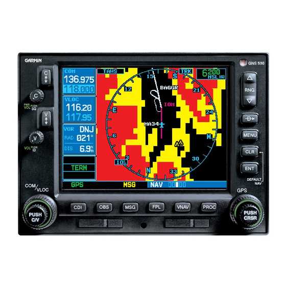
To activate the selected frequency, press the frequencies you’ll be using for the first phase of your appropriate flip-flop key—COM for commu- flight. The GNS 530W display is divided into separate nication frequencies or VLOC for VOR/Localizer ‘windows’ (or screen areas), including a COM window, frequencies. -
Page 20: Page Groups
TAKEOFF TOUR Page Groups Page Groups (Large right knob to change page groups) NAV Group WPT Group AUX Group Default NAV Airport Location Airport Departure Flight Planning Airport Runway Intersection Utility Airport Frequency NDBs Setup 1 Terrain Airport Approach Setup 2 NAVCOM Satellite Status Airport Arrival... - Page 21 TAKEOFF TOUR Page Groups (Large right knob to change page groups) NRST Group FPL Group VNAV (Press FLP) (Press VNAV) Nearest Airport Nearest Center Active Flight Plan Vertical Navigation Nearest Intersection Nearest FSS Flight Plan Catalog PROC (Press PROC) Nearest NDB Nearest Airspace Procedures NOTE: The number of NAV pages avail-...
-
Page 22: Nav Pages
See the 400W/500W Series Display Interfaces Pilot’s Guide Addendum, part number 190- To select the desired NAV page, turn the small right 00356-31 and the 400W/500W Series Garmin knob until the desired page is displayed. Optional Displays Pilot’s Guide Addendum, part If you are currently viewing a page that is not part number 190-00356-30. -
Page 23: Default Nav Page
TAKEOFF TOUR Default NAV Page Default NAV Page To change the data fields in the corners of the Default NAV Page: During most flights, the Default NAV, Map and Press MENU (with the Map Page displayed). NAVCOM pages are the primary pages used for navi- gation. -
Page 24: Map Page
By adding data fields along the right-hand side, the Map Page can After the GNS 530W acquires satellites and com- combine a moving map display putes a position, the Map Page appears automatically. -
Page 25: Navcom Page
TAKEOFF TOUR NAVCOM Page NAVCOM Page Frequency List Frequency Type The Navigation/Communications (NAVCOM) Page provides a complete list of airport frequencies at your departure, en route and arrival airports. A frequency listed on the NAVCOM Page can be quickly transferred to the standby field of the COM or VLOC windows. -
Page 26: Direct-To Navigation
TAKEOFF TOUR Direct-To Navigation Direct-To Navigation Press ENT to confirm the identifier. The “Acti- vate?” function field is highlighted. The 500W-series unit can use direct point-to-point navigation to guide you from takeoff to touchdown, even in the IFR environment. Once a destination is selected, the unit provides course and distance data based upon a direct course from your present position to your destination. -
Page 27: Ifr Procedures
TAKEOFF TOUR IFR Procedures IFR Procedures Turn the small right knob to select the desired procedure and press ENT. Once the direct-to or flight plan is confirmed, the whole range of instrument procedures is available to you. Departures (SIDs), arrivals (STARs), non-preci- sion and precision approaches are stored within the NavData card and available using the PROC key. -
Page 28: Nearest Pages
TAKEOFF TOUR Nearest Airports Nearest Pages To display the NRST pages: If necessary, press the small right knob to The NRST page group provides listings for nearest remove the cursor from the page. airports or other facilities. The NRST group includes detailed information on the 25 nearest airports, VORs, Turn the large right knob to select the NRST NDBs, intersections and user-created waypoints within... -
Page 29: Nearest Airport Page
TAKEOFF TOUR Nearest Airports Nearest Airport Page The Nearest Airport Page may be used in conjunc- tion with the direct-to key to quickly set a course to You may examine both the communication a nearby facility in an in-flight emergency. Selecting a frequencies and runway information directly from nearby airport as a direct-to destination overrides your the Nearest Airport Page. -
Page 30: Nearest Airspace Page
TAKEOFF TOUR Nearest Airspace Nearest Airspace Page The last page in the NRST group, the Nearest Airspace Page, provides information for up to nine controlled or special-use airspaces near or in your flight path. Airspace information appears on this page based upon the same criteria used for airspace alert messages. -
Page 31: Flight Plans
TAKEOFF TOUR Flight Plans Flight Plans The 500W-series unit lets you create up to 20 flight plans, with up to 31 waypoints in each flight plan. Flight plans are created, edited and activated using the FPL key. The FPL page group includes two pages: the Active Flight Plan Page and the Flight Plan Catalog. - Page 32 TAKEOFF TOUR Flight Plans Press the small right knob to remove the highlighting. Once the flight plan is created, it may be activated from an options window. Activating the flight plan copies it into “flight plan 00” (the original flight plan still resides in the Flight Catalog) and replaces any flight plan which currently exists in “flight plan 00.”...
-
Page 33: Section 1 Communicating Using The Gns 530W
You may override the squelch function by pressing the COM power/ The GNS 530W features a digitally-tuned VHF volume knob. This facilitates listening to a distant sta- COM radio that provides a seamless transition from tion or setting the desired volume level. -
Page 34: Com Window And Tuning
1 - COM Com Window and Tuning GNS 530W only COM Window and Tuning Communication frequencies are selected with the tuning cursor in the standby COM frequency field, and using the large and small left knobs to dial in the desired frequency. The standby frequency always appears below the active frequency. -
Page 35: Auto-Tuning
Auto-Tuning CTAF frequency and press ENT to place the The GNS 530W’ s auto-tune feature allows frequency in the standby field of the COM you to quickly select any database frequency in window. - Page 36 1 - COM Auto-Tuning FSS & Center Freqs GNS 530W only To display the entire list of frequencies for a To select a COM frequency for a nearby flight nearby airport and select from that list: service station (FSS) or center (ARTCC):...
- Page 37 1 - COM Auto-Tuning from Flight Plan GNS 530W only To select a COM frequency for any airport in your To select a COM frequency for any airport in the flight plan: database: Select the NAVCOM Page from the NAV page Select the Airport Frequencies Page from the group.
-
Page 38: Emergency Channel
GNS 530W only Emergency Channel Stuck Microphone The GNS 530W’ s emergency channel select pro- Whenever the GNS 530W is transmitting, a vides a quick method of selecting 121.500 MHz as the “TX” indication appears in the COM window. If the active frequency in the event of an in-flight emergency. -
Page 39: Section 2 Nav
2 - NAV PAGES Page Groups / NAV Page Group Section 2 The NAV page group includes five, or more, pages. While viewing any NAV page, turn the small right NAV Pages knob to select a different NAV page. You may find Main Page Groups this selection process convenient to cycle between The 500W-series main pages are divided into groups:... -
Page 40: Default Nav Page
2 - NAV PAGES Default NAV Page Default NAV Page NOTE: Approaching the FAF, the GNS 500W-series unit automatically rescales in an angular fashion. This The first NAV page is the Default NAV Page. This allows the LPV approach to be flown identically to a page may be quickly selected from ANY page by using standard ILS. -
Page 41: Selecting Desired On-Screen Data
2 - NAV PAGES Default NAV Page Selecting Desired On-Screen Data NOTE: The 500W-series unit always navigates TO a waypoint unless the OBS switch is set (preventing At the corners of the Default NAV Page are four automatic waypoint sequencing), or you have passed user-definable fields which display the data you need the last waypoint in your flight plan. -
Page 42: Restoring Factory Settings
NAV Page. This option allows you to transfer a direct- to destination, the active flight plan, any stored flight plan or user waypoints to a second 400W or 500W- series Garmin unit. Once “Change Fields?” is selected, use the Some crossfill operations can be done automati- large right knob to select the field you wish... -
Page 43: Default Nav Page Auto Zoom
2 - NAV PAGES Map Page Default Nav Page Auto Zoom Map Page The second NAV page is the map page, which dis- An autozoom feature is available for the Default plays your present position using an airplane symbol, NAV Page, which automatically adjusts from an en along with nearby airports, navaids, user-defined route range of 200 nautical miles through each lower waypoints, airspace boundaries, lakes, rivers, high-... -
Page 44: Map Symbols
2 - NAV PAGES Map Page NOTE: If the 500W-series unit is unable to determine a GPS position, the present position (airplane) symbol will appear on the Map Page in yellow. No symbol will be present when there is no active flight plan. Map Symbols Various symbols are used to distinguish between waypoint types. -
Page 45: Map Panning
2 - NAV PAGES Map Panning the map using the CLR key. To quickly declutter the map display, press the CLR key momentarily (as often as needed) to select the desired amount of map detail. Panning the map lets you look beyond the boundaries of the current map area without changing the scale. -
Page 46: Map Direct-To
2 - NAV PAGES Map Direct-To To review information for an on-screen airport, Airspace Information on the Map navaid or user waypoint: When a special-use or controlled airspace bound- Use the panning function (as described on the ary appears on the map display, you can quickly previous page) to place the target pointer on retrieve information —... - Page 47 2 - NAV PAGES Airspace Information Press the ENT key to display the Page Menu. Highlight “Review Airspace?”. Press ENT to display the airspace information. Press ENT again to return to the Nav page. Press ENT to view the frequencies. Turn the large right knob to scroll through the avail- able frequencies.
-
Page 48: Map Page Options
2 - NAV PAGES Map Page Options Map Page Options Press ENT to view the frequency information. Many of the 500W-series functions are menu Press ENT with “Done?” highlighted to return driven. Each of the main pages has an options menu, to the airspace frequency display. -
Page 49: Map Setup
2 - NAV PAGES Map Setup Map Setup To change a map setup feature: “Setup Map?” allows you to configure the map Press MENU (with the Map Page displayed). display to your preferences, including map orientation, Turn the large right knob to highlight “Setup land data enable/disable, Jeppesen data enable/disable, Map?”... -
Page 50: Distance Measurements
2 - NAV PAGES Distance Measurements To enable/disable the on-screen wind vector*: Distance Measurements Turn the small right knob to select “Map” The “Measure Dist?” option provides a quick, easy and press ENT. Use the large right knob to method for determining the bearing and distance highlight the “Wind Vector”... -
Page 51: Data Fields On The Map
2 - NAV PAGES Data Fields on the Map Data Fields on the Map Selecting Desired On-Screen Data The “Data Fields On?” option provides a map “Change Fields?” allows you to choose the data dis- display (shown at right) with five user-selectable data played on the five user-selectable data fields along the fields along the right-hand side of the screen. -
Page 52: Restoring Factory Settings
2 - NAV PAGES Restoring Factory Settings NOTE: The on-screen traffic information (TRFC) oc- cupies two data fields, leaving room to display only three additional data types. Traffic information is only available when the 500W-series unit installation includes connection to traffic information sources. See the 400W/500W Series Display Interfaces Pilot's Guide Addendum. -
Page 53: Terrain Operation
2 - NAV PAGES Terrain Operation Terrain Operation The Terrain Page has two selectable view settings: • 360˚ View—View from above aircraft depicting During power-up of the 500W Series unit, the surrounding terrain on all sides terrain/obstacle database versions are displayed along •... -
Page 54: Inhibit Mode
General Database Information The Garmin TERRAIN system uses terrain and obstacle information supplied by government sources. The data undergoes verification by Garmin to confirm accuracy of the content, per TSO-C151b. However, the information displayed should never be understood to be all-inclusive. Pilots must familiarize themselves Inhibiting Terrain with the appropriate charts for safe flight. -
Page 55: Database Versions
Terrain Operation Database Versions NOTE: The data contained in the terrain and obstacle databases comes from government agencies. Garmin The version and area of coverage of each ter- accurately processes and cross-validates the data, but rain/obstacle database is shown on the Terrain Data- cannot guarantee the accuracy and completeness of base Versions Page, located in the AUX Page Group. -
Page 56: Database Updates
Visit the United States: Limited to the United States, some Garmin website to check for newer versions of terrain/ areas of Canada, Mexico, the Caribbean, and the obstacle databases. Compare database cycle numbers Pacific. -
Page 57: Navigation Database
Departure Phase - Defined as when all five of the As explained in the “Premature Descent Alerting following conditions are met: (PDA)” section, the Garmin Terrain premature descent • It has been determined that the aircraft was previ- ously “on-ground.”... -
Page 58: Terrain Destination Airport
2 - NAV PAGES Terrain Alerts TERRAIN Alerts TERRAIN alerts are issued when flight conditions meet parameters that are set within the TERRAIN system software algorithms. When an alert is issued, visual annunciations are displayed. Annunciations appear in a dedicated field in the lower left corner of the display. -
Page 59: Forward Looking Terrain Avoidance
2 - NAV PAGES Terrain Alerts Forward Looking Terrain Avoidance • Imminent Terrain Impact (ITI) Avoidance — Pro- vides alerts when the aircraft is below the eleva- The Forward Looking Terrain Avoidance alert, or tion of a terrain cell in the aircraft’ s projected path. FLTA, is used by the TERRAIN system and is com- ITI alerts are accompanied by a potential impact posed of two elements: Reduced Required Terrain Clear-... -
Page 60: Premature Descent Alerting (Pda)
2 - NAV PAGES Terrain Alerts Premature Descent Alerting (PDA) TERRAIN Failure Alert The TERRAIN system issues a Premature Descent The TERRAIN system continually monitors Alert (PDA) when the system detects that the aircraft several system-critical items, such as database validity, is significantly below the normal approach path to hardware status, and GPS status. -
Page 61: Terrain Not Available" Alert
2 - NAV PAGES Terrain Alerts “TERRAIN Not Available” Alert The TERRAIN system requires a 3D GPS navigation solution along with specific vertical accuracy minimums. Should the navigation solution become degraded, if the terrain/obstacle database is not available, or if the aircraft is out of the database coverage area, the annunciation “TERRAIN NOT AVAILABLE”... - Page 62 2 - NAV PAGES Terrain Alerts Alert Type Annunciation Pop-Up Alert TERRAIN Failure None TERRAIN Inhibited None TERRAIN Not Available None Required Terrain Clearance (RTC) Advisory Required Terrain Clearance (RTC) Alert (FLASHING) (FLASHING) Imminent Terrain Impact (ITI) Advisory Imminent Terrain Impact (ITI) Alert (FLASHING) (FLASHING) Required Obstacle Clearance (RTC) Advisory...
-
Page 63: Navcom Page
2 - NAV PAGES NAVCOM Page NAVCOM Page To select a frequency list for a departure, en route or arrival airport: The NAVCOM Page provides a list of the airport Press the small right knob to activate the communication and navigation frequencies at your cursor. - Page 64 To place a frequency in the standby field of the COM or VLOC window, highlight the desired frequency (using the large right knob) and press ENT. Available in the GNS 530W only. Some listed frequencies may include designations for limited usage, as follows: “TX”...
-
Page 65: Satellite Status Page
2 - NAV PAGES Satellite Status Page Satellite Status Page As the GPS receiver locks onto satellites, a signal The Satellite Status Page (the last NAV page) strength bar appears for each satellite in view, with the provides a visual reference of GPS receiver functions, appropriate satellite number (01-32, WAAS satel- including current satellite coverage, GPS receiver lites will have higher numbers) underneath each bar. - Page 66 2 - NAV PAGES Satellite Status Page Turn the small right knob to display the list of available data items. Continue turning the small right knob to select the desired data item from the list. As satellites are received, the status changes to “3D Navigation”.
-
Page 67: Dead Reckoning
2 - NAV PAGES Dead Reckoning Dead Reckoning Each satellite has a 30-second data transmission that must be collected (hollow signal strength bar) Dead reckoning is the process of continuing navi- before the satellite may be used for navigation (solid gation using your last known position and speed after signal strength bar). - Page 68 2 - NAV PAGES Dead Reckoning Dead Reckoning mode will continue until GPS posi- tion is restored, when GPS navigation is restored Dead Reckoning mode is exited. The DR annunciations will be removed and GPS information will be used to compute navigation related information for the current flight phase.
-
Page 69: Section 3 Direct-To Navigation
3 - DIRECT-TO Selecting a Destination Section 3 Direct-To Navigation The 500W-series direct-to function provides a quick method of setting a course to a destination waypoint. Once a direct-to is activated, the 500W-series unit establishes a point-to-point course line (geodesic path) from your present position to the selected direct-to destination. -
Page 70: Selecting A Destination By Facility Name Or City
3 - DIRECT-TO Selecting by Facility or City Selecting a Destination by Facility Name or Turn the large right knob to highlight the City facility name (second line; see above) or the In addition to selecting a destination by identifier, city (third line;... -
Page 71: Selecting A Destination From The Active Flight Plan
3 - DIRECT-TO Flight Plan / Nearest Waypoints Selecting a Destination from the Active Flight Selecting the Nearest Airport as a Direct-To Desti- Plan nation The Select Direct-to Waypoint Page always displays If you’re navigating an active flight plan, any the nearest airports (from your present position) on waypoint contained in the flight plan may be selected the NRST field. -
Page 72: Shortcuts
3 - DIRECT-TO Direct-to Shortcuts Shortcuts Direct-to destinations may also be selected from Shortcuts are available when using the direct-to the Map Page by panning to the desired destination key, allowing you to bypass the use of the small and location and pressing direct-to and ENT (twice). -
Page 73: Cancelling Direct-To Navigation
3 - DIRECT-TO Cancelling / Manual Course Cancelling Direct-To Navigation Specifying a Course to a Waypoint Once a direct-to is activated, the 500W-series unit When you perform a direct-to, the 500W-series provides navigation guidance to the selected destina- unit sets a direct geodetic course to your selected tion until the direct-to is either replaced with a new destination. -
Page 74: Selecting Direct-To A Holding Pattern
3 - DIRECT-TO Selecting Direct-To a Holding Pattern The holding pattern will now be set as your next waypoint. You may select a Direct-To course to a holding pat- tern that is in your flight plan. To set a direct-to course to a holding pattern: Press the FPL key to reach the active flight plan page. -
Page 75: Section 4 Flight Plans
4 - FLIGHT PLANS Creating Flight Plans Section 4 Flight Plans The 500W-series unit lets you create up to 20 differ- ent flight plans, with up to 31 waypoints in each flight plan. The flight plan (FPL) page group consists of two pages, accessed by pressing the FPL key. - Page 76 4 - FLIGHT PLANS Editing Flight Plans To delete a waypoint from an existing flight plan: To change the comment line for an existing flight plan: Press FPL and turn the small right knob to display the Flight Plan . Press the small right knob to activate the cursor.
-
Page 77: Flight Plan Catalog Options
4 - FLIGHT PLANS Activating / Inverting Flight Plan Catalog Options Turn the large right knob to highlight the desired flight plan and press MENU to display The following options are available for the Flight the Flight Plan Catalog Options. Plan Catalog: Turn the large right knob to highlight “Acti- •... -
Page 78: Crossfill
flight plan, any stored flight plan or user waypoints to a second 400W-series or 500W- series Garmin unit. Some crossfill operations can be done automatically. If the crossfill method for both units is set to “auto”, a change in the direct-to destina- tion or active flight plan on one unit can also be seen... -
Page 79: Copying Flight Plans
4 - FLIGHT PLANS Flight Plan Catalog Options the “Cross-Side” field, then turn the small right knob to select “To” or “From”. Press ENT to confirm the selection. Turn the large right knob to highlight “Initi- ate Transfer?” and press ENT to transfer the selected data. -
Page 80: Deleting Flight Plans
4 - FLIGHT PLANS Flight Plan Catalog Options Deleting Flight Plans Delete All Flight Plans Once you are finished with a flight plan, it can Delete All Flight Plans? allows you to remove all easily be deleted from the Flight Plan Catalog or the flight plans from memory at one time. -
Page 81: Active Flight Plan
4 - FLIGHT PLANS Active Flight Plan Options Active Flight Plan The Active Flight Plan Page provides information and editing functions for “flight plan 0” — the flight plan currently in use for navigation. Once you have activated a flight plan, the Active Flight Plan Page shows each waypoint for the flight plan, along with the desired track (DTK), distance (DIS) for each leg and cumulative distance (CUM). -
Page 82: Activate Leg
4 - FLIGHT PLANS Active Flight Plan Options Activate Leg page in the Flight Plan section. Activate Leg? activates/reactivates the flight plan Invert Flight Plan and selects the highlighted leg as the “active leg” (the Invert Flight Plan? reverses the active flight plan. leg which is currently used for navigation guidance). -
Page 83: Select Approach
4 - FLIGHT PLANS Active Flight Plan Options Select Approach final course segment of the approach and will provide navigation guidance to intercept this Select Approach? allows you to select a published final course.) instrument approach for the destination airport, or replace the current approach with a new selection. -
Page 84: Select Departure
4 - FLIGHT PLANS Active Flight Plan Options Select Departure Select Departure? allows you to select a pub- lished standard instrument departure (SID) for the departure airport, or replace the current departure with a new selection. When using a direct-to, the 500W-series unit uses the nearest airport as a refer- ence when displaying available departures. -
Page 85: Remove Approach, Arrival, Or Departure
4 - FLIGHT PLANS Active Flight Plan Options Remove Approach, Arrival, or Departure Closest Point of FPL Remove Approach? deletes the currently selected Closest Point of FPL? calculates the bearing and closest distance at which a flight plan passes from approach from the active flight plan. -
Page 86: Parallel Track
4 - FLIGHT PLANS Active Flight Plan Options highlight “Load?” and press ENT. The name Points to remember with Parallel Track: for the new user waypoint is derived from the • You must have an active flight plan identifier of the reference waypoint. •... -
Page 87: Change Fields
4 - FLIGHT PLANS Active Flight Plan Editing Turn the small right knob to select the desired To cancel a parallel track to your flight plan. Offset Direction and press ENT. With the Active Flight Plan Page displayed, press MENU to display the Active Flight Plan Activate? is highlighted. -
Page 88: Restore Defaults
4 - FLIGHT PLANS Flight Plan Shortcuts Restore Defaults Turn the large right knob to highlight the title for the approach, departure or arrival you wish Restore Defaults? returns the data items to fac- to delete. Titles appear in light blue directly tory defaults. - Page 89 4 - FLIGHT PLANS Flight Plan Shortcuts The “Activate Leg?” option is discussed earlier, When using instrument procedures, this feature which allows you to specify which leg of the flight can be used not only to activate a specific point-to- plan is currently used for navigation guidance.
- Page 90 4 - FLIGHT PLANS Blank Page...
-
Page 91: Section 5 Approaches, Departures, & Arrivals
5 - PROCEDURES Approaches/Departures/Arrivals Section 5 are offered for the nearest airport.) Approaches, Departures, & Arrivals A second window appears listing the avail- able transitions. Turn the large right knob to The 500W-series unit allows you to fly non-preci- sion and precision approaches to airports with pub- highlight the desired transition waypoint and press ENT. - Page 92 5 - PROCEDURES Activating Approaches 2. Turn the large right knob to highlight “Acti- Not all approaches in the database are approved for vate Approach?” and press ENT. GPS use. As you select an approach, a “GPS” designa- tion to the right of the procedure name indicates the Another Procedures Page option allows you to procedure can be flown using the GPS receiver.
- Page 93 5 - PROCEDURES Basic Approach Operations the screen. If you have passed the MAP, the 500W- Annunciation Description series unit proceeds to the transition waypoint without Follow lateral and vertical guidance to LPV a restart confirmation. minimums. A yellow background indicates the current VPL and/or HPL values are not Basic Approach Operations adequate for the approach and is an early...
-
Page 94: Approaches With Procedure Turns
5 - PROCEDURES Procedure Turn Approach “Activate” the full approach or vectors-to-final, Approach operations on the 500W-series units as appropriate. In some scenarios, you may find typically begin with the same basic steps: it more convenient to immediately activate the approach and skip the “Load” process outlined above in step #3. -
Page 95: Flying The Procedure Turn
5 - PROCEDURES Procedure Turn Approach Prior to departing KFDK, the destination (KLYH) is selected using the direct-to key or by cre- ating a flight plan terminating at Lynchburg Regional. While en route to KLYH, some 40-50 nauti- cal miles away, you select the ATIS frequency to monitor airport conditions and runway usage. - Page 96 5 - PROCEDURES Procedure Turn Approach 31 nm RW04 As you approach the IAF, the “Left to 209° in x sec” waypoint alert appears in the lower right corner. Prepare to turn to this heading. Fly the outbound course, keeping the CDI ...
- Page 97 5 - PROCEDURES Procedure Turn Approach When within 45° of the final approach course DO NOT and the FAF is the TO waypoint, the 500W- USE FOR RW04 series unit switches from terminal mode to NAVIGATION “approach” mode. CDI scaling is tightened from 1.0 NM full scale deflection to either 0.3 nautical mile or 2°...
-
Page 98: Flying The Missed Approach
5 - PROCEDURES Missed Approach 13. As you cross the MAP, “SUSP” appears Flying the Missed Approach above the OBS key, indicating that automatic After you pass the MAP, if the runway isn’t in sequencing of approach waypoints is sus- sight you must execute a missed approach. -
Page 99: Flying An Approach With A Hold
5 - PROCEDURES Approach with Hold (or another approach) press the PROC key to NOTE: In some cases, an additional hold waypoint is added to the missed approach sequence. This “Select Approach?” or “Activate Approach?” additional waypoint is used as an aid in establishing as previously described. - Page 100 5 - PROCEDURES Approach with Hold From the transitions window, select BODRY As in the last example, within 31 nautical miles intersection as the IAF, assuming that ATC has of the airport, the 500W-series unit switches cleared you direct to the BODRY intersection. from en route mode to terminal mode, and the Also, select “Activate?”...
- Page 101 5 - PROCEDURES Approach with Hold NOTE: If you need to lose extra altitude or speed by going around the holding pattern again, press OBS to manually suspend waypoint sequencing BEFORE crossing the holding waypoint the sec- (IAF) ond time.
- Page 102 5 - PROCEDURES Approach with Hold 13. As you cross the FAF, the destination sequences to the MAP (“RW21”, the runway threshold). With the needle centered, fly toward the MAP, observing the altitude minimums dictated by the approach plate. As you approach the MAP, the “Arriving at waypoint”...
-
Page 103: Flying A Dme Arc Approach
5 - PROCEDURES DME Arc Approach Flying a DME Arc Approach approach is selected, along with “D258G/LEBVY” as the IAF. The GPS overlay for a DME arc approach uses Select Billard Muni (KTOP) as your destination, additional Jeppesen-provided waypoints to define the via the direct-to key or as the last waypoint arc. - Page 104 5 - PROCEDURES DME Arc Approach NOTE: Since this is not a GPS approach, the pilot DO NOT USE FOR should be using the VLOC receiver, tuned to the correct NAVIGATION VOR (TOP) for navigation. However, as an example, operation is essentially identical.
- Page 105 5 - PROCEDURES DME Arc Approach The next point in the approach is an interme- DO NOT USE FOR diate fix, labeled “D025G/DMARY”. As you NAVIGATION approach this intermediate fix, a waypoint alert (“Right to 205° in x sec”) appears in the lower right corner of the screen.
-
Page 106: Vectors To Final
5 - PROCEDURES Vectors-To-Final Approach 11. As you approach the MAP, a waypoint alert Vectors to Final (“Arriving at waypoint”) appears in the lower Let’ s take a second look at the “VOR 22” approach right corner of the screen. CDI scaling continues into Billard Municipal. -
Page 107: Flying The Vectors Approach
5 - PROCEDURES Vectors-To-Final Approach Select “Load?” (or “Activate?”, if already on Flying the Vectors Approach vectors-to-final). With “Vectors-To-Final” (VTF) selected, the CDI To activate vectors-to-final from the procedures needle remains off center until you’re established on page: the final approach course. With the approach acti- Select Billard Muni (KTOP) as your destination, vated, the Map Page displays an extension of the final using the direct-to key or as the last waypoint... - Page 108 5 - PROCEDURES Vectors-To-Final Approach If you haven’t already done so, activate the approach (with vectors-to-final). This allows the 500W-series unit to guide you to the final approach course. As you converge with the final approach course, the CDI needle (on the Default NAV Page and the external CDI) moves toward the center.
-
Page 109: Course From Fix Flight Plan Legs
5 - PROCEDURES Course-From-Fix Legs Make any course adjustments necessary for the Course From Fix Flight Plan Legs final course segment (FAF to MAP). After the Certain approach, departure, and arrival procedures FAF, VLOC guidance should be used for this in the Jeppesen database contain Course From Fix flight approach. - Page 110 5 - PROCEDURES Course-From-Fix Legs As the distance to the IAF approaches zero, At 13.0 nautical miles from the IAF, a the waypoint alert is replaced by a turn waypoint alert appears (“Next DTK 265° in x advisory (“Right to 072° in x sec”). Initiate a sec”).
- Page 111 5 - PROCEDURES Course-From-Fix Legs to tighten from 0.3 NM to 350 feet, full-scale MISSED APPROACH: deflection. Palmdale (CA) USAF Plant 42 As you cross the MAP, “SUSP” appears VOR/DME or GPS Rwy 25 above the OBS key, indicating that automatic ...
- Page 112 5 - PROCEDURES Course-From-Fix Legs speed and distance from PMD VOR. Intercept and fly the inbound course, keeping the CDI needle centered. As you approach PMD VOR (the missed approach holding point), an alert message in the lower right-hand corner of the screen recommends the holding pattern entry proce- dure (“Hold parallel”).
- Page 113 5 - PROCEDURES Course-From-Fix Legs TYPE 3: Course from fix to manual sequence As you depart the airfield, “Next DTK 026° in Course from fix to manual sequence legs appears on x sec” appears in the lower right corner of the the Active Flight Plan and Map Pages with “man seq”...
-
Page 114: Ils Approaches
VLOC window (left side of screen) and the CDI output set to “VLOC”. The GNS 530W can be set to automatically switch the external CDI output from GPS to VLOC as you intercept the final approach course (if used with a KAP140/KFC225 autopilot, you will need to manually enable outputs). -
Page 115: Selecting An Ils Approach
2.0 nautical miles from the FAF, For this example, we’ll use a flight from Laughlin the GNS 530W does not automatically switch the CDI Bullhead (Arizona) International (KIFP) to Flag- to VLOC. In this case, press the CDI key to manually switch from GPS to VLOC. -
Page 116: Flying The Ils Approach
5 - PROCEDURES ILS Approach GNS 530W only simply press the VLOC flip-flop key to place it in the active frequency field. Flying the ILS Approach When you “Activate?” an ILS approach, automatic switching of the external CDI is enabled (unless turned off from the CDI/Alarms Page). - Page 117 5 - PROCEDURES ILS Approach GNS 530W only to do so when cleared for the approach. See “Approaches with Procedure Turns” in this section, step #4 for a description of this opera- tion. As you approach the IAF (SHUTR), a waypoint alert (“Left to 032°...
- Page 118 (“Left to 255° appears in the lower left corner of the screen in x sec”) to intercept the ILS. The GNS 530W — indicating a CDI scale transition from 1.0 sequences to the inbound leg and “Left to 210°...
- Page 119 5 - PROCEDURES ILS Approach GNS 530W only is displayed on the Default NAV Page, but DO NOT USE FOR course guidance along the final approach NAVIGATION course continues. Do NOT follow this extended course. Follow published missed approach procedures using the OBS key to initiate the missed approach sequence.
-
Page 120: Selecting An Lpv Approach
5 - PROCEDURES LPV Approach Selecting an LPV Approach Flying the LPV Approach Within 31 nautical miles of KSLE, the GNS For this example, we’ll use a flight from Eugene 500W Series unit switches from en route mode Oregon (KEUG) to Salem, Oregon (KSLE) and select to terminal mode and the CDI scale transitions the RNAV runway 31 approach. - Page 121 5 - PROCEDURES LPV Approach Sixty seconds prior to reaching the FAF (LOTKE), the unit will check the required HorizontalAlarm Limit (HAL) and Vertical Alarm Limit (VAL) to ensure the GPS position integrity is within limits to complete the LPV precision approach. In the event the HAL or VAL limits are exceeded, the approach will be downgraded to a non-preci- sion approach indicated by “LNAV”...
-
Page 122: Lnav/Vnav And Lnav Approaches With Advisory Vertical Guidance
5 - PROCEDURES LNAV Approach 11. Fly the guidance provided by the unit to the series unit automatically sequences through each ARTTY intersection and hold. leg of the approach unless “SUSP” appears above LNAV/VNAV and LNAV Approaches with Advi- the OBS key. “SUSP” indicates that automatic sory Vertical Guidance sequencing of approach waypoints is suspended on GPS approaches with vertical guidance may be... -
Page 123: Points To Remember For Localizer Or Vor-Based Approaches
5 - PROCEDURES Additional Approach Info Points to Remember for Localizer or VOR- switch to the VLOC receiver with sufficient time to based Approaches capture and track the approach course. Switching • The default factory setting allows the CDI output to to “VLOC”... -
Page 124: Enabling Autopilot Outputs For The King Kap140/Kfc225
5 - PROCEDURES Enabling Autopilot Outputs The localizer frequency must be active to use Guidance to the FAF is active as indicated by “VLOC” guidance at the MAP. Press the CDI Approach mode annunciation (LNAV, LNAV+V, key to switch back to GPS data when the L/VNAV, or LPV). -
Page 125: Section 6 Wpt
6 - WPT PAGES WPT Page Group Section 6 To quickly select a WPT page: From any page, press and hold CLR to select WPT Pages the Default NAV Page. (You may skip this step WPT Page Group if you are already viewing any of the main Section 2 introduced the 500W-series unit main pages.) page groups —... -
Page 126: Finding The Desired Airport
6 - WPT PAGES Finding the Desired Airport Finding the Desired Airport Turn the small right knob to select the desired character. Your 500W-series unit uses ICAO identifiers for all Repeat steps 3 and 4 until the identifier is airports. All U.S. airport identifiers which contain only selected, then press ENT. -
Page 127: Duplicate Waypoints
6 - WPT PAGES Duplicate Waypoints To remove the flashing cursor, press the small To select a facility name or city location, where duplicate entries exist: right knob. Select the desired facility name or location. Duplicate Waypoints As you spell the facility name or location, Once the identifier, facility name or location is using the small and large right knobs, the entered, all six airport pages display information for... -
Page 128: Airport Location Page
6 - WPT PAGES Airport Location Airport Location Page • Radar — Radar coverage: Yes or No • Airspace — Control environment: Class C, The Airport Location Page displays the latitude, CTA, TMA, TRSA, Class B or longitude, and elevation of the selected airport. The none Airport Location Page also displays facility name and location, as well as fuel availability, best available... -
Page 129: Airport Location Page Options
6 - WPT PAGES Airport Runways Airport Location Page Options Airport Runway Page The Airport Runway Page displays runway des- Select Next FPL Apt? ignations, length, surface type and lighting for the Selecting the Next Airport page menu option selected airport. A map image of the runway layout allows you to display the next waypoint in the and surrounding area is also displayed on the Airport flight plan. -
Page 130: Airport Runway Page Options
6 - WPT PAGES Airport Runways Turn the small right knob to display a window Airport Runway Page Options listing all runways for the selected airport. Select Next FPL Apt? Continue turning the small right knob to As described earlier in this section. select the desired runway. -
Page 131: Airport Frequency Page
To scroll through the frequency list and tune to a desired frequency on the list (tuning is only available The Airport Frequency Page displays radio fre- with the GNS 530W or 530AW): quencies and frequency types for the selected airport, Identifier, Symbol... -
Page 132: Airport Frequency Page Options
6 - WPT PAGES Airport Frequencies To view usage restrictions for a frequency: The following descriptions and abbreviations are used on the Airport Frequency Page: Turn the large right knob to place the cursor on the “Info?” designation directly to the left •... -
Page 133: Airport Approach Page
6 - WPT PAGES Airport Approaches Airport Approach Page The Airport Approach Page shows the available approach procedures for the selected airport. Where multiple initial approach fixes (IAFs) and feeder routes are available, that information may also be displayed. A map image provides a layout diagram for each approach and transition. -
Page 134: Airport Approach Page Options
6 - WPT PAGES Airport Approach Options Airport Approach Page Options NOTE: Not all approaches in the database are ap- proved for GPS use. As you select an approach, a The following options are available for the Airport “ ” designation to the right of the procedure name Approach Page, by pressing the MENU key: indicates the procedure can be flown using the GPS re- ceiver. - Page 135 6 - WPT PAGES Airport Approach Options To load and activate an approach from the Airport To select an approach channel from the Airport Approach Page, follow the steps above, but select Approach Page: “Load and Activate?” in step #3. Press MENU to display the Airport Approach Page Options.
-
Page 136: Airport Arrival Page
6 - WPT PAGES Airport Arrivals Airport Arrival Page Turn the small right knob to display a window of available arrivals for the selected The Airport Arrival Page shows the available airport. Continue turning the small right Airport Standard Terminal Arrival (STAR) procedures knob to select the desired arrival. -
Page 137: Airport Arrival Page Options
6 - WPT PAGES Airport Arrivals From the Airport Arrival Page, press MENU With the “RUNWAY” field highlighted, turn to display an options list. “Load into Active the small right knob to select the desired FPL?” allows you to add the arrival procedure runway. -
Page 138: Airport Departure Page
6 - WPT PAGES Airport Departures To manually transition to a loaded arrival proce- Airport Departure Page dure: The Airport Departure Page shows the available From the Active Flight Plan Page, press the Airport Departure Procedures (DPs; also referred to as small right knob to activate the cursor and SIDs) for the selected airport. -
Page 139: Airport Departure Page Options
6 - WPT PAGES Airport Departures Turn the small right knob to display a window of available departures for the selected airport. Continue turning the small right knob to select the desired departure. Press ENT. The cursor moves to the runway field. -
Page 140: Intersection Page
6 - WPT PAGES Intersections To load a departure procedure from the Airport Intersection Page Departure Page: The Intersection Page displays the latitude, longi- Select the desired departure, runway and transi- tude, region and country for the selected intersection. tion using the steps above. The Intersection Page also displays the identifier, radial Press MENU to display the Airport Departure and distance from the nearest VOR, VORTAC or VOR/... -
Page 141: Ndb Page
6 - WPT PAGES NDBs NDB Page The NDB page displays the facility name, city, region/country, latitude and longitude for the selected NDB. The NDB page also displays the frequency and a weather broadcast indication (if applicable). There are no options for the NDB page. The following descrip- tions and abbreviations are used: Identifier and Latitude/Longitude... -
Page 142: Vor Page
6 - WPT PAGES VORs VOR Page VORs may be selected by identifier, facility name or location (city). The VOR Page may also be used to The VOR Page displays the facility name, city, quickly tune the VLOC receiver to the selected VOR’ s region/country, magnetic variation, latitude and lon- frequency. -
Page 143: User Waypoint Page
6 - WPT PAGES User Waypoints To select a VOR frequency from the VOR Page: User Waypoint Page Select the VOR Page from the WPT page In addition to the airport, VOR, NDB and intersec- group. tion information contained in your Jeppesen NavData ®... -
Page 144: Creating User Waypoints
6 - WPT PAGES Creating User Waypoints The following descriptions and abbreviations appear on the User Waypoint Page: • REF WPT — Reference waypoint identifier (name) • RAD — Radial from reference waypoint, in degrees magnetic or degrees true (depending upon unit con- figuration) Use the small and large right knobs to enter •... - Page 145 6 - WPT PAGES Creating User Waypoints To create a new user waypoint by referencing an NOTE: The 500W-series units allow you to create a new user waypoint at a defined radial and existing waypoint: distance from your present position. To reference With the User Waypoint Page displayed, press your present position, follow the steps above, the small right knob to activate the cursor.
-
Page 146: Creating User Waypoints From The Map Page
6 - WPT PAGES Creating User Waypoints Creating User Waypoints from the Map Page To capture and save your present position as a user waypoint: The Map Page and panning target pointer provide a With the Map Page displayed, press the small quick means of saving your present position as a user- right knob to activate the panning function. -
Page 147: Modifying User Waypoints
6 - WPT PAGES Modifying User Waypoints Press the small right knob to remove the flashing cursor. Modifying User Waypoints To modify a user waypoint by changing reference waypoint information: To modify an existing waypoint, select that With the User Waypoint Page displayed, press waypoint on the User Waypoint Page and enter the the small right knob to activate the cursor. -
Page 148: User Waypoint Page Options
6 - WPT PAGES User Waypoint Options The cursor moves to the radial (RAD) field. Use User Waypoint Page Options the small and large right knobs to change the The following User Waypoint Page Options are radial from the reference waypoint, if desired. available by pressing the MENU key (with the User Press ENT to accept the selected radial. -
Page 149: User Waypoint List
6 - WPT PAGES User Waypoint List User Waypoint List Delete User Waypoint? allows you to delete the selected waypoint from memory. The User Waypoint List allows you to review, To delete a user waypoint: modify, rename or delete a selected user waypoint, or to delete all user waypoints currently stored in memory. - Page 150 6 - WPT PAGES User Waypoint List To rename a user waypoint from the User To delete a user waypoint from the User Waypoint List: Waypoint List: Select the User Waypoint List. Select the User Waypoint List. Turn the large right knob to highlight the Turn the large right knob to highlight the desired user waypoint.
- Page 151 6 - WPT PAGES User Waypoint List To delete all user waypoints from memory: Select the User Waypoint List. Press MENU to display an options window for the User Waypoint List. With the User Waypoint List displayed, press MENU to display an options window with “Delete All User Waypoints?”...
- Page 152 6 - WPT PAGES Blank Page...
-
Page 153: Nrst Page Group
7 - NRST PAGES NRST Page Group Section 7 NRST Pages NRST Page Group Section 2 introduced the 500W-series unit main page groups — NAV, WPT, AUX, NRST — and described each page in the NAV group. This fourth page group (NRST) provides detailed information for the 25 nearest airports, VORs, NDBs, intersections and user waypoints within 200 NM of your current position. -
Page 154: Section 7 Nrst
NRST Pages / Scrolling To quickly select a NRST page: waypoints or airspaces in the list. In the GPS 500W, press NRST. For the GNS 530W, To scroll through the list of nearest airports, VORs, NDBs, intersections, user waypoints or airspaces:... -
Page 155: Navigating To A Nearby Waypoint
7 - NRST PAGES Nearby Waypoints To scroll through the list of nearest flight service station Navigating to a Nearby Waypoint or center points of communication: The NRST pages can be used in conjunction with the 500W-series unit direct-to function to quickly set a course to a nearby facility. -
Page 156: Nearest Airport Page
The Nearest Airport Page may be used to quickly tune the COM transceiver (GNS 530W only) to a nearby airport. The selected frequency is placed in the To quickly tune to a frequency on the Nearest standby field of the COM window and activated using... -
Page 157: Nearest Intersection Page
7 - NRST PAGES Nearest Intersections and NDBs Press the small right knob to remove the To return to the Nearest Airport Page, verify flashing cursor. that “Done?” is highlighted by the flashing cursor and press ENT (or press CLR). Additional communication frequencies, runway information and more is available from the Near- est Airport Page by highlighting the identifier of the... -
Page 158: Nearest Vor Page
For each VOR listed, the Nearest VOR Page also indi- cates the frequency and may be used to quickly tune the VLOC receiver to the nearby VOR (GNS 530W only). The selected frequency is placed in the standby field of the VLOC window and activated using the To quickly tune a VOR’s frequency from the... -
Page 159: Nearest User Waypoint Page
Turn the large right knob to scroll down the placed in the standby field of the COM window and page, highlighting the desired frequency. activated using the COM flip-flop key (GNS 530W Press ENT to place the selected frequency in only). -
Page 160: Nearest Flight Service Station (Fss) Page
Press the COM flip-flop key to activate the To quickly tune an FSS’s frequency from the Near- selected frequency. est Flight Service Station Page (GNS 530W only): Select the Nearest Flight Service Station Press the COM flip-flop key to activate the Page. -
Page 161: Nearest Airspace Page
7 - NRST PAGES Nearest Airspaces Press ENT to place the frequency on standby. “Airspace near and ahead” indicates that you Press the COM or VLOC flip-flop key to are within two nautical miles of an airspace activate the selected frequency.Navigation and projected to enter the airspace. - Page 162 7 - NRST PAGES Nearest Airspaces To view additional details for an airspace listed trolled airspace are also sectorized to provide complete on the Nearest Airspace Page: information on any nearby airspace. Once one of the Select the Nearest Airspace Page. described conditions exists, the message annunciator flashes, alerting you of an airspace message (if airspace alert messages are enabled).
- Page 163 7 - NRST PAGES Nearest Airspaces To view and quickly tune the frequency for a controlling agency: Follow steps #1 through #4 on the previous page to display the Airspace Information Page for the desired controlled or special use airspace. “Done?”...
- Page 164 7 - NRST PAGES Nearest Airspaces The Airspace Information Page displays — and air- The bottom right-hand corner of the Airspace space alert messages are provided for — the following Information Page displays the floor and ceiling limits airspace types: of the airspace.
-
Page 165: Section 8 Vloc (Vor/Localizer/Glideslope)
VLOC frequency field, and using Receiver Operations the small and large left knobs to dial in the desired The GNS 530W includes digitally-tuned VOR/ frequency. The standby frequency always appears localizer and glideslope receivers with the desired below the active frequency. -
Page 166: Vloc Ident Window
8 - VLOC RECEIVER VLOC Ident Window GNS 530W only To select a VOR/localizer/ILS frequency: VLOC Ident Window Directly below the VLOC Tuning If the tuning cursor is not currently in the VLOC Window is a VLOC Ident Window window, press the small left knob momen- (default setting). - Page 167 flight plan without imme- approach procedure is “Loaded” or “Activated”, the diately using it for navigation guidance. This GNS 530W automatically places the proper frequency allows you to continue navigating the original in the standby field of the VLOC window. If you wish flight plan, but keeps the procedure available...
-
Page 168: Cdi Key
8 - VLOC RECEIVER CDI Key CDI Key The GNS 530W’ s CDI key is used to couple the GPS or VLOC receiver to the external CDI (or HSI). When the external CDI (or HSI) is connected to the GPS receiver, “GPS” appears at the bottom left corner of the page, directly above the CDI key. -
Page 169: Section 9 Aux
9 - AUX PAGES AUX Page Group Section 9 To quickly select an AUX page: AUX Pages From any page, press and hold CLR to select the Default NAV Page. (You may skip this step AUX Page Group if you are already viewing any of the main Section 2 introduced the 500W-series unit main pages.) page groups —... -
Page 170: Flight Planning Page
9 - AUX PAGES Flight Planning Flight Planning Page The Flight Planning Page provides access to E6B functions for fuel planning, trip planning, density altitude/true airspeed/winds aloft calculations, sched- uled messages and a “Crossfill” function to transfer flight plans/user waypoints to a second 500W-series unit. - Page 171 9 - AUX PAGES Flight Planning figure and is not retained the next time you Density Alt / TAS / Winds — indicates the view the page. theoretical altitude at which your aircraft per- forms depending upon several variables, including •...
- Page 172 Crossfill — allows the pilot to transfer the active flight plan, any stored flight plan, a user waypoint or all user waypoints between two 500W-Series (or 400W-Series) Garmin units in a dual-unit instal- lation. To perform fuel planning operations: Select “Fuel Planning” from the Flight Planning Page.
- Page 173 9 - AUX PAGES Flight Planning The flashing cursor moves to the fuel flow (FF) field. Use the small and large right knobs to enter the fuel flow rate. Press ENT when finished. Note that if a fuel system is providing current fuel flow, the fuel flow defaults to this value.
- Page 174 9 - AUX PAGES Flight Planning select the desired leg of the flight plan, or select With all variables entered, the following infor- “Cum” to apply trip planning calculations to mation is provided: the entire flight plan. • DTK — Desired track, or desired course Turn the large right knob to highlight the •...
- Page 175 9 - AUX PAGES Flight Planning The flashing cursor moves to the total air tem- To enter a scheduled message: Select “Scheduler” from the Flight Planning perature (TAT) field. Use the small and large Page. right knobs to enter the temperature. Press ENT when finished.
- Page 176 9 - AUX PAGES Flight Planning To select Crossfill Select “Crossfill?” from the Default NAV Page or Flight Plan Page by pressing MENU or while on the Flight Planning Page by scrolling down to “Crossfill” and pressing ENT. Use the small and large right knobs to enter the time or date.
- Page 177 • Active Flight Plan — transfers the active flight plan to/from a second 500W-Series (or 400W-Series) Garmin unit in a dual unit installation. This option is the default when selecting “Crossfill” from the Flight Planning Page.
-
Page 178: Utility Page
9 - AUX PAGES Utility Page Continue turning the small right knob to Utility Page select the desired data option. Press ENT when The Utility Page provides access to checklists, a finished. count down/up timer, trip timers, trip statistics, RAIM 5a. - Page 179 RAIM during approach previous item. operations and warns you if RAIM is not available. In such cases, use the GNS 530W’ s VLOC receiver The following items are available: instead for the approaches. RAIM prediction helps you Checklists —...
-
Page 180: Checklists
9 - AUX PAGES Utility Page Use the small and large right knobs to enter Software Versions — provides software version each checklist item followed each time by ENT. information for the operating software within the GPS (Each checklist may contain up to 30 line items receiver, COM transceiver, VOR/localizer receiver, up to sixteen characters in length.) glideslope receiver and main processor board. - Page 181 9 - AUX PAGES Utility Page To delete a checklist or all checklists: Flight Timers With the Checklists Page displayed, press To view, use or reset the generic timer: MENU to display an options menu. Select “Flight Timers” from the Utility Page. Turn the large right knob to select “Delete The flashing cursor highlights “Start?”.To start Checklist?”...
- Page 182 9 - AUX PAGES Utility Page To record or reset the departure time: To view, use or reset total trip time: Select “Flight Timers” from the Utility Page. Select “Flight Timers” from the Utility Page. Turn the large right knob to highlight the Turn the large right knob to highlight the reset mode field, under “Departure Time”.
-
Page 183: Trip Statistics
9 - AUX PAGES Utility Page Trip Statistics RAIM Prediction To predict RAIM availability: To reset trip statistics readouts: Select “RAIM Prediction” from the utility Select “Trip Statistics” from the Utility Page. page. Press MENU to display an options window The flashing cursor highlights the waypoint with several reset options: field. -
Page 184: Software Versions
9 - AUX PAGES Utility Page Database Versions • RAIM Not Available — Satellite coverage is predicted to NOT be The Database Versions Page displays the current sufficient for reliable operation during non- Jeppesen database type, effective date, and expiration precision approaches date, along with the version and type of built-in land database. -
Page 185: Setup 1 Page
9 - AUX PAGES Setup 1 Page Setup 1 Page Turn the large right knob to select the desired item, and press ENT. The Setup 1 Page provides access to airspace alarms, CDI scale adjustments, an arrival alarm, units of measure settings, position formats, map datums, settings for local or UTC time display, display adjust- ments, nearest airport search parameters, data field configurations and COM transceiver channel spacing. - Page 186 9 - AUX PAGES Setup 1 Page - Setup 1 for ILS CDI Selection details. CDI scales and corresponding flight phases: En Route CDI / Alarms Page Terminal If a lower CDI scale setting is selected (i.e., 1.0 or 0.3 NM), the higher scale settings are not selected during ANY phase of flight.
- Page 187 9 - AUX PAGES Setup 1 Page less than 500 feet above or below an airspace and the correct number of hours. projected to enter it, you will be notified with an Not all time zones are offset from UTC by a whole alert message.
-
Page 188: Cdi / Alarms
9 - AUX PAGES Setup 1 Page Press the small right (CRSR) knob twice to for runway length and “any” for runway surface exit the selection process. type. COM Configuration — allows you to select Data Field Configuration — determines the 8.33 kHz or 25.0 kHz COM frequency channel information type that is displayed in the user- spacing. - Page 189 9 - AUX PAGES Setup 1 Page field. Use the small and large right knobs to enter the desired buffer distance. Press ENT when finished. NOTE: The CDI scale is always displayed in nautical miles, regardless of the current distance units of mea- sure selected on the Units / Position Page.
-
Page 190: Units / Position
9 - AUX PAGES Setup 1 Page To set the arrival alarm and alarm distance: To change the units of measure: Select “CDI / Alarms” from the Setup Page. Select “Units / Position” from the Setup Page. Turn the large right knob to highlight the Turn the large right knob to highlight the “On”/”Off”... -
Page 191: Date / Time
9 - AUX PAGES Setup 1 Page To change the position format: Date / Time Select “Units / Position” from the Setup To display local time or UTC: Page. Select “Date / Time” from the Setup Page. Turn the large right knob to highlight the The flashing cursor highlights the “Time “Position Format”... -
Page 192: Display Backlight
9 - AUX PAGES Setup 1 Page Nearest Airport Criteria To set the minimum runway length and runway surface: Select “Nearest Airport Criteria” from the Setup Page. The flashing cursor highlights the “Runway Surface” field. Turn the small right knob to select the desired surface. -
Page 193: Data Field Configuration
9 - AUX PAGES Setup 1 Page display traffic information. This allows you NOTE: Exercise caution when changing the Near- est Airport Criteria. Remember, by excluding certain to monitor traffic conditions from ANY page surface types or shorter runway lengths, you may be and quickly identify traffic hazards. -
Page 194: Com Configuration
Page. Press MENU to display a page options window. With “Restore Defaults?” highlighted, press ENT. 8.33 kHz and 25.0 kHz channel spacing are available for the GNS 530W’s COM trans- ceiver. Use the 25.0 kHz setting in the United States. -
Page 195: Setup 2 Page
9 - AUX PAGES Setup 2 Page Setup 2 Page SBAS Selection To enable WAAS operation, in the Setup 2 page select the SBAS (Space-Based Augmentation System) item and then select WAAS. If WAAS is disabled, the unit will not be able to fly vertically guided GPS approaches (LPV, LNAV/VNAV, or LNAV+V). - Page 196 9 - AUX PAGES Setup 2 Page Blank Page...
-
Page 197: Section 10 Vertical Navigation (Vnav)
10 - VNAV Vertical Navigation Page Section 10 Vertical Navigation (VNAV) The 500W-series Vertical Navigation Page allows you to create a three-dimensional profile which guides you from your present position and altitude to a final (target) altitude at a specified location. This is helpful when you’d like to descend to a certain altitude near an airport. - Page 198 10 - VNAV Vertical Navigation Profile To create a vertical navigation profile: Press VNAV to display the Vertical Navigation Page. Press the small right knob to activate the TIME AND DISTANCE TO PROFILE cursor. CURRENT ALTITUDE AND POSITION With the “Target Altitude” field highlighted, turn the small and large right knobs to select TARGET ALTITUDE AND POSITION...
- Page 199 10 - VNAV VNAV Messages The default profile utilizes a 400 foot-per- Vertical navigation messages can be turned on or minute descent rate. To change the rate, turn off. (By default the messages are off.) Turning the mes- the large right knob to highlight the “VS sages off allows you to keep the profile settings you’ve Profile”...
-
Page 200: Section 11 Fault Detection And Exclusion (Fde)
The FDE consists of two distinct features, fault specified route of flight). Please, refer to the instruc- detection and fault exclusion. The fault detection tions included in the Garmin 400W/500W-series feature detects the presence of an unacceptably large Training CD for complete details on using the FDE pseudorange error for a satellite (and presumably, prediction program. -
Page 201: Messages Abbreviations & Nav Terms
All data referenced to True North — the unit’ s Heading base. TAWS audio alerts are not available. The unit should mode has been set to “True” in the AUX Setup pages. be returned to your Garmin dealer for service. - Page 202 (land data) database. Land data does not appear on the Map Page. COM has failed — (GNS 530W only) The unit has Other unit functions continue to work normally, however detected a failure in its communications transceiver. The...
- Page 203 12 - MESSAGES ABBREVIATIONS & NAV TERMS COM transfer key stuck — (GNS 530W only) The Database changed, validate user modified procedures COM flip-flop key is stuck in the enabled (or “pressed”) — You have modified one or more approaches, departures state.
- Page 204 12 - MESSAGES ABBREVIATIONS & NAV TERMS G/S has failed — (GNS 530W only) The unit has detected Inside airspace — Your GPS-calculated position lies a failure in its glideslope receiver. The glideslope receiver within the boundaries of a special use airspace. This mes-...
- Page 205 flip-flop key to “activate” the frequency. seconds. If the problem persists, the installation should be Select VLOC on CDI for approach — (GNS 530W only) checked by your Garmin dealer. You are inbound and within 3 nautical miles of the FAF;...
- Page 206 TAWS inhibit key stuck — The external TAWS inhibit VLOC has failed — The GNS 530W has detected a failure key is stuck. in its VLOC receiver. The VLOC receiver is not available TERRAIN configuration conflict —...
-
Page 207: Turn Advisory And Arrival Annunciations
ABBREVIATIONS & NAV TERMS Turn Advisory and Arrival Annunciations VLOC remote transfer key is stuck — (GNS 530W only) The remote VLOC transfer switch is stuck in the The following annunciator messages may appear in the enabled (or “pressed”) state. Try pressing the switch again lower right corner of the 500W-series unit display: to cycle its operation. - Page 208 12 - MESSAGES ABBREVIATIONS & NAV TERMS Blank Page...
-
Page 209: Abbreviations
12 - MESSAGES ABBREVIATIONS & NAV TERMS Abbreviations CUM — Cumulative The following is a list of abbreviations and acronyms DB — Database used on the and their meanings: 500W-series unit DEN — Density ACTV — Active DEP — Departure ALT —... - Page 210 12 - MESSAGES ABBREVIATIONS & NAV TERMS FPL — Flight Plan kHz — Kilohertz fpm — Feet Per Minute km — Kilometers FREQ — kph — Frequency Kilometers Per Hour FSS — Flight Service Station kt — Knots ft — Feet L/VNAV —...
- Page 211 12 - MESSAGES ABBREVIATIONS & NAV TERMS Position formats PWR — Power MHz — Megahertz RAD — Radial mi — Statute Miles RAIM — Receiver Autonomous Integrity Moni- toring MOA — Military Operations Area REF — Reference mph — Statute Miles Per Hour REQ —...
- Page 212 12 - MESSAGES ABBREVIATIONS & NAV TERMS TKE — Track Angle Error WAAS — TMA — ICAO Terminal Control Area Wide Area Augmentation System TRANS — Transition WPT — Waypoint TRFC — Traffic WX — Weather TRK — Track (also Ground Track) Angle TRSA —...
-
Page 213: Navigation Terms
12 - MESSAGES ABBREVIATIONS & NAV TERMS Navigation Terms expressed in distance per fuel units (e.g., nautical The following navigation terms are used on the miles per gallon). 500W-series unit: ENDUR (endurance) — Flight endurance, or total available flight time based upon available fuel. WPT 2 NORTH EPU (estimated position uncertainty) —... - Page 214 12 - MESSAGES ABBREVIATIONS & NAV TERMS LFOB (left-over fuel onboard) — The amount of TKE to zero. fuel remaining on board after the completion of one or TRK (track) — The direction of movement relative to more legs of a flight plan (or a direct-to). a ground position.
-
Page 215: Appendix A Navdata Card Use
APPENDIX A NavData Card Use Appendix A swing arm handle. NavData Card Use Turn the swing arm handle outward until it locks into place, perpendicular to the face of The Jeppesen NavData ® card supplied with your the 500W-series unit. 500W-series unit should be installed or removed only Grasp the swing arm handle between your when the 500W-series unit is off. -
Page 216: Appendix B Specifications
APPENDIX B Specifications Appendix B Specifications PHYSICAL VOR PERFORMANCE (GNS 530W only) Unit Size: 6.25”W x 11.00”D x 4.60”H Frequency Range: 108.00 MHz to 117.95 MHz (159mm x 279mm x 117mm) LOCALIZER PERFORMANCE Unit Weight with tray: (GNS 530W only) Frequency Range: 108.10 MHz to... -
Page 217: Appendix C Troubleshooting Q & A
RAIM is not available. The 500W-series unit see your authorized dealer or contact Garmin directly automatically monitors RAIM and warns you with an alert at the address or phone numbers listed on page ii. - Page 218 APPENDIX C Troubleshooting Q & A Why aren’t there any approaches available for my flight plan? Approaches are available for the final destination air- port in a flight plan or as a direct-to (keep in mind that some VOR/VORTAC identifiers are similar to airport iden- tifiers).
- Page 219 APPENDIX C Troubleshooting Q & A What does the OBS key do and when do I use it? When should I use the OBS key to return to auto sequencing, and what happens when I do? The OBS key is used to select manual (OBS mode) or The most common application for using the OBS key to suspend automatic sequencing of waypoints.
- Page 220 APPENDIX C Troubleshooting Q & A How do I skip a waypoint in an approach, departure, When does turn anticipation begin, and what bank or arrival? angle is expected? The 500W-series unit allows you to manually select any The 500W-series unit smooths adjacent leg transitions approach, departure or arrival leg as the active leg of your based upon a nominal 15º...
- Page 221 APPENDIX C Troubleshooting Q & A When does the CDI scale change and what does it change to? The 500W-series unit begins a smooth CDI scale tran- sition from the 2.0 NM (en route mode) to the 1.0 NM (terminal mode) scale within 31 NM from the destination airport (see below).
- Page 222 APPENDIX C Troubleshooting Q & A How do I re-select the same approach or activate a new approach after a missed approach? After flying all missed approach procedures, you may reactivate the same approach for another attempt from the Procedures Page. Once you have been given clearance for another attempt, activate the approach from the Proce- dures Page by highlighting “Activate Approach?”...
-
Page 223: Index
APPENDIX D Index Index Localizer 113 LPV 110 Missed approach 88 Symbols Procedure turn 84 VTF 97 3D navigation 8, 56, 57 ARINC 195, 206 Arrival 17, 73, 81, 126, 180, 191, 210 ARTCC 18, 26, 143, 144, 149, 199 Abbreviations 118, 120, 122, 130, 131, 132, 134, 191, 199 Auto-tuning 24, 25, 156 Accessories iii... - Page 224 Display backlight 177, 182, 192 Distance 180 Distance measurements 40 GAD 194 DME arc 30, 93 Geodesic 203 DP 81, 128, 199 Glideslope 194, 206 Dual units 32 GNS 530W/AW 1 Duplicate waypoints 117 GPS 194, 206 GPS 500W 1 Great circle 203...
- Page 225 APPENDIX D Index Auto zoom 34 HFOM 57 Datum 181 Hide aviation data 44 Page 14, 33, 38 Hold 89, 197 Panning 35 HSI 59 Range 31 Scale 34, 120 Setup 39 Symbols 34 Ident audio and volume 155 MAPR 83 IFR procedures 17 Map scale 14 ILS 104, 179...
- Page 226 APPENDIX D Index Sort list 70 Specifications 206 Packing list iii Speed 180 Page groups 10 Squelch 23 Page summary 10 Standard package iii Panning 35 Standby frequency 9 Parallel track 76 STARs 17, 81 Phase of flight 47 Stormscope 196 Physical size 206 Stuck microphone 28 Position 177, 180...
- Page 227 APPENDIX D Index Vertical speed 180, 189 VFOM 57 VHF com 206 View frequencies 37 VLOC 2, 9, 148, 155, 195, 196 VNAV 4, 187, 191 Volume 2, 23 VOR 132, 148, 206 VSR 189 VTF 82, 96 WAAS approach ID 123, 125 Warranty iv Waypoints 115 Waypoint alert 29...
- Page 228 APPENDIX D Index Blank Page...
- Page 230 © 2006 Garmin Ltd. or its subsidiaries Garmin International, Inc. 1200 East 151 Street, Olathe, Kansas 66062, U.S.A. Garmin AT, Inc. 2345 Turner Rd., S.E., Salem, Oregon 97302, U.S.A. Garmin (Europe) Ltd. Unit 5, The Quadrangle, Abbey Park Industrial Estate, Romsey, SO51 9DL, U.K.