Table of Contents
Advertisement
Quick Links
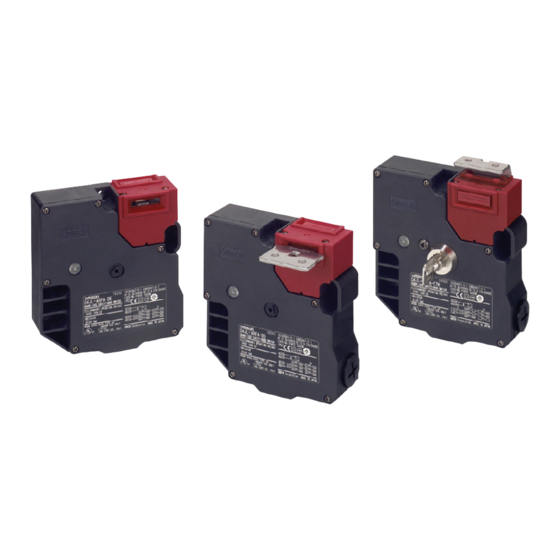
Guard Lock Safety-door Switch
D4JL
World's Top* Holding Force of 3,000 N
*For plastic models, as of May 2005
• Two safety circuits and two monitor contacts provide an array of
monitoring patterns.
• Standard gold-clad contacts enable use with ordinary loads and
microloads.
• Models with trapped keys prevent workers from being locked in
hazardous work areas.
• Models with rear release buttons allow people to unlock the
Switch and escape if they are locked into hazardous areas.
• IP67 degree of protection
Note: Be sure to read the "Safety Precautions" on page 68 and the
"Precautions for All Safety Door Switches" on page 2.
Features
Plastic Guard Lock Safety-door Switches
Rank Among the Strongest in the World
A holding force of 3,000 N makes these Switches suitable for large,
heavy doors.
Models with Trapped Keys
(See page 55 for a list of models.)
OMRON also offers Trapped Key Switches (on mechanical lock
models only). The door can be opened only by supplying power to
the solenoid and then turning the trapped key to unlock the D4JL. As
long as a person has the trapped key when he enters a hazardous
area, he cannot be accidentally locked inside by someone else.
There are thirty different types of trapped keys available for use in
applications with adjacent hazardous areas.
Two Safety Circuits and Two Monitor
Contacts
The D4JL has two safety circuits. It also has two contacts to
separately monitor the open/closed status of the door and the status
of the lock.
Door Open/Closed
Lock Monitor Switch
Detection Switch
41
42
11
51
52
21
63
64
33
Monitoring
Monitoring the open/
the door lock
closed status of the door
Models with Rear Release Buttons
(See page 54 for a list of models.)
A Switch with a rear release button allows the door to be unlocked
from inside a hazardous area in an emergency. OMRON also offers
Switches with Special Slide Keys. Refer to the "D4NS-SK/D4JL-SK"
on page 130 for details.
Rear release button
Guard Lock Safety-door Switch
12
To safety circuit
To safety circuit
22
To control circuit
34
Special slide key
D4JL
51
Advertisement
Table of Contents

Related Manuals for Omron D4JL-1NFA-C5


Summary of Contents for Omron D4JL-1NFA-C5
- Page 1 A Switch with a rear release button allows the door to be unlocked Models with Trapped Keys from inside a hazardous area in an emergency. OMRON also offers Switches with Special Slide Keys. Refer to the “D4NS-SK/D4JL-SK” (See page 55 for a list of models.) on page 130 for details.
-
Page 2: Model Number Structure
Model Number Structure ■ Model Number Legend Switches Operation Keys D4JL-@@@@-@@-@@ D4JL-K@ 1 2 3 4 1. Conduit Size 1. Operation Key Type 1: Pg13.5 1: Horizontal mounting 2: G1/2 2: Vertical mounting 3: 1/2-14NPT (See note 2.) 4: M20 2. -
Page 3: Ordering Information
Indicator Lock and release types Contact configuration Conduit opening Model (door open/closed detection switch and lock monitor switch contacts) Special release key Green Mechanical lock 2NC/1NO+2NC/1NO PG13.5 D4JL-1NFA-C5 Solenoid release G1/2 D4JL-2NFA-C5 1/2-14NPT D4JL-3NFA-C5 D4JL-4NFA-C5 2NC/1NO+3NC PG13.5 D4JL-1PFA-C5 G1/2 D4JL-2PFA-C5... - Page 4 Models with Rear Release Buttons Release key type Indicator Lock and release types Contact configuration Conduit opening Model (door open/closed detection switch and lock monitor switch contacts) Special release key Green Mechanical lock 2NC/1NO+2NC/1NO PG13.5 D4JL-1NFA-C6 Solenoid release G1/2 D4JL-2NFA-C6 1/2-14NPT D4JL-3NFA-C6 D4JL-4NFA-C6...
- Page 5 Models with Trapped Keys Release key type Indicator Lock and release types Contact configuration Conduit opening Model (door open/closed detection switch and lock monitor switch contacts) Trapped key Green Mechanical lock 2NC/1NO+2NC/1NO PG13.5 D4JL-1NFA-C7-01 (See note.) Solenoid release G1/2 D4JL-2NFA-C7-01 1/2-14NPT D4JL-3NFA-C7-01 D4JL-4NFA-C7-01...
-
Page 6: Specifications
3. The durability is for an ambient temperature of 5 to 35°C and an ambient humidity of 40% to 70%. For further conditions, consult Current consumption Approx. 200 mA your OMRON sales representative. Insulation Class F (130°C max.) 4. Do not pass a 3-A, 250-VAC load through more than two circuits. -
Page 7: Internal Circuit Diagram
Connections ■ Indicators • Direct opening contacts used as safety-circuit input are indicated with the mark. Terminals 11-12 and terminals 21-22 are direct opening contacts. Internal Circuit Diagram • Do not connect the indicator directly to direct opening contacts. If indicator is connected in parallel with direct opening contacts, a 24 VDC O1 (+) - Page 8 Nomenclature ■ Structure of D4JL-@@@A-5 and D4JL-@@@G-@5 Operation Key hole Solenoid Operation Key hole Example for Terminal E1 (+) D4JL-@N@@-@5 Terminal E2 (−) Lock Monitor Door Open/Closed Terminal 01 Switch Detection Switch Terminal 02 Terminal 11 To safety circuit Terminal 12 LED indicator Terminal 21 Terminal 22...
- Page 9 ■ Structure of D4JL-@@@A-@6 Operation Key hole Solenoid Operation Key hole Example for Terminal E1 (+) D4JL-@N@A-@6 Terminal E2 (−) Lock Monitor Door Open/Closed Terminal 01 Switch Detection Switch Terminal 02 Terminal 11 To safety circuit Terminal 12 LED indicator Terminal 21 Terminal 22 To safety circuit...
- Page 10 ■ Structure of D4JL-@@@A-@7-@@ Operation Key hole Solenoid Operation Key hole Example for Terminal E1 (+) D4JL-@N@A-@7@@ Terminal E2 (−) Lock Monitor Door Open/Closed Terminal 01 Switch Detection Switch Terminal 02 Terminal 11 To safety circuit Terminal 12 LED indicator Terminal 21 Terminal 22 To safety circuit...
-
Page 11: Operation Method
Operation Method ■ Operation Principles Mechanical Lock Models Solenoid Lock Models Operation Key removed. Operation Key removed. Cross-sectional view B-B Cross-sectional view B-B Operation Key inserted: Door locked. Operation Key inserted: Door unlocked. Cross-sectional view B-B Cross-sectional view B-B Solenoid ON: Door unlocked. Solenoid ON: Door locked. - Page 12 Trapped Key Models (1) Operation Key removed, solenoid OFF, and trapped key Operation Key inserted, solenoid ON, and trapped key inserted. removed. Status: Door locked and trapped key can be removed. Cross-sectional view B-B Cross-sectional view B-B (2) Operation Key inserted, solenoid OFF, and trapped key (5) Operation Key inserted, solenoid ON, and trapped key removed.
- Page 13 Dimensions Note: All units are in millimeters unless otherwise indicated. ■ Dimensions and Operating Characteristics Switches Head cap D4JL-@@F@-C5 D4JL-@@F@-D5 (Thickness of the auxiliary mounting tool) Black Operation Key Auxiliary mounting tool Set zone Operation Key Four, 23.6 5.4-dia. 36.5 Six cover mounting screws holes 49.5...
- Page 14 D4JL-@@FA-C7 Head cap D4JL-@@FA-D7 (Thickness of the auxiliary mounting tool) Black (74) Set zone Operation Key Operation Key Auxiliary mounting tool Four, 23.6 5.4-dia. 36.5 holes Six cover mounting screws 49.5 43.5 (13) Indicator 23.5 10.0 (132.9) (5.8) (56) 81.9 76.5 Cap screw (42.5)
- Page 15 With Operation Key Inserted D4JL+D4JL-K1 (with Front-inserted Operation Key) D4JL+D4JL-K2 (with Front-inserted Operation Key) Black Black Key insertion position Key insertion position (48.8 min, 52.1 max.) (55.8 min, 59.1 max.) Horizontal insertion radius: Vertical insertion radius: R≥270 R≥270 (36.5) (36.5) Center tolerance of Center tolerance of key hole: ±0.8...
-
Page 16: Application Examples
Application Examples G9SA-321-T@ (24 VAC/VDC) + D4JL-@@@A-@@ (Mechanical Lock Models) Manual Reset Application Example Lock release Stopping a Robot on a Conveyor Line signal Door OPEN D4NH Safety-door Hinge Switches D4JL Guard Lock Safety-door Switches Door Feedback loop OPEN Stop signal A1 A2 T11 13 23 33 43 53 61 OffDelay... - Page 17 G9SX-AD322-T15 (24 VDC) + D4JL-@@@A-@@ (Mechanical Lock Models)/Manual Reset Application Example Machining section doors Tool changer door Machining Center • The entire machining center will stop when the emergency stop button is pressed. • Power will not be supplied to the Emergency Safety Door Safety Door...
-
Page 18: Safety Precautions
Safety Precautions Refer to the “Precautions for All Switches” on page B-2 and “Precautions for All Safety Door Switches” on page 2. • Do not use metal connectors or metal conduits when using ½- DANGER 14NPT connectors. Damage to the conversion adapter may result in an improper seal or electric shock. - Page 19 (mechanical lock models only). • Do not operate the Switch with anything other than the special OMRON Operation Key, otherwise the Switch may break or the • After setting the release key to UNLOCK to, for example, change safety of the system may not be maintained.
- Page 20 89± • Do not operate the Switch with anything other than the special OMRON Operation Key. Otherwise, the Switch may be damaged and the safety of the system may not be maintained. • Ensure that the alignment offset between the Operation Key and the key hole does not exceed ±0.8 mm.
-
Page 21: Recommended Connectors
Wiring Processing the Conduit Opening • Connect a recommended connector to the opening of the conduit and tighten the connector to the proper torque. The case may be Circuit Connection Example damaged if excessive tightening torque is applied. • Direct opening contacts used for safety circuit inputs are indicated •... - Page 22 Other Precautions • A Guard Lock Safety-door Switch will heat when power is supplied to the solenoid. Do not touch these Switches. • Perform maintenance inspections periodically. ALL DIMENSIONS SHOWN ARE IN MILLIMETERS. To convert millimeters into inches, multiply by 0.03937. To convert grams into ounces, multiply by 0.03527. Cat.