Viessmann Vitotronic 200 Installation And Service Instructions Manual
Hide thumbs
Also See for Vitotronic 200:
- Service instructions manual (336 pages) ,
- Installation and service instructions for contractors (136 pages) ,
- Installation and service instructions manual (120 pages)
Table of Contents

Related Manuals for Viessmann Vitotronic 200


Summary of Contents for Viessmann Vitotronic 200
- Page 1 VIESMANN Installation and service instructions for contractors Vitotronic 200 Type GW1 Weather-compensated, digital boiler control unit For applicability, see the last page VITOTRONIC 200 Please keep safe. 5592 801 GB 2/2007...
-
Page 2: Safety Instructions
Safety instructions Safety instructions Please follow these safety instructions closely to prevent accidents and material losses. Safety instructions explained the Code of Practice of relevant trade associations, Danger all current safety regulations as This symbol warns against the defined by DIN, EN, DVGW, TRGI, risk of injury. - Page 3 Instal- charge static loads. ling non-authorised compo- nents and non-approved modifications/conversion can compromise safety and may invalidate our warranty. For replacements, use only ori- ginal spare parts from Viessmann or those which are approved by Viessmann.
- Page 4 Index Index Installation instructions Preparing for installation System version 1 ..................System version 2 ..................System version 3 ..................System version 4 ..................10 System extension ..................11 Installation sequence Overview of electrical connections .............. 15 Inserting cables and applying strain relief............ 16 Inserting the boiler coding card ..............
- Page 5 Index Index (cont.) Troubleshooting Faults that are displayed at the programming unit ........56 Function description Boiler water temperature control ..............66 Heating circuit control ................. 71 Cylinder temperature control ............... 76 Coding Resetting codes to their delivered condition ..........81 Code 1......................
-
Page 6: System Version
Vitoplex 200, type SX2, to 560 kW Vitorond 200, type VD2A, to 270 KW Vitoplex 300, type TX3 For function description see page 67. A Boiler with Vitotronic 200 with C Vitotronic 200-H with LON communication module LON communication module... - Page 7 Vitoplex 300, type TX3 Vitoplex 100, type SX1 Vitorond 200, type VD2 Vitoplex 200, type SX2 For function description see page 68. A Boiler with Vitotronic 200 with C Vitotronic 200-H with LON communication module LON communication module B DHW cylinder...
- Page 8 Vitoplex 300, type TX3 Vitoplex 100, type SX1 Vitorond 200, type VD2 Vitoplex 200, type SX2 For function description see page 68. A Boiler with Vitotronic 200 with C Vitotronic 200-H with LON communication module LON communication module B DHW cylinder...
- Page 9 Preparing for installation System version 3 (cont.) Plug DHW circulation pump Outside temperature sensor Shunt pump § Boiler water temperature sen- fÖ Power supply, 230 V/50 Hz Burner stage 1 Cylinder temperature sensor gS A1 Mixer motor, return tempera- aJA Temperature sensor T1 ture raising facility aJB Temperature sensor T2 lÖ...
- Page 10 For systems without low temperature heating circuit, always connect to the lower return connector. Connect at least 15 % of the rated output to the lower return connector. E Low temperature heating circuit A Boiler with Vitotronic 200 with LON communication module F Underfloor heating circuit B DHW cylinder...
-
Page 11: System Extension
Preparing for installation System version 4 (cont.) H Secondary pump (for wiring, see page 24) K Primary pump (for wiring, see page 24) Plug Cylinder primary pump Outside temperature sensor DHW circulation pump § Boiler water temperature sen- fÖ Power supply, 230 V/50 Hz Burner stage 1 Cylinder temperature sensor lÖ... - Page 12 Preparing for installation System extension (cont.) A Boiler with Vitotronic 200 B Vitocell 100-L C Vitotrans 222 Plug sÖ A1 Primary pump Terminals 1 and 2: Secondary pump Cylinder temperature sensor 1 DHW circulation pump (top) gS A1 Three-way mixing valve motor...
- Page 13 F Shunt pump G Control thermostat, part no. Z001 886 In conjunction with system version 3 A separate Vitotronic 200-H must be The boiler control unit affects the con- used for regulating the Vitotrans 222. stant return temperature control (see coding address "4E").
- Page 14 Preparing for installation System extension (cont.) System with flue gas/water heat exchanger A Boiler with Vitotronic 200 B Vitotrans 300 C Circulation pump for Vitotrans 300 Circulation pump for Vitotrans 300 The circulation pump is started paral- lel to the burner.
-
Page 15: Overview Of Electrical Connections
Installation sequence Overview of electrical connections Note When connecting plugs aVD, aVH, sA and sK, bundle the individual cores of the cables closely to the terminals. This ensures that, in case of failure, for example when detaching a wire, the wires cannot drift into the adjacent voltage area. -
Page 16: Inserting Cables And Applying Strain Relief
Installation sequence Overview of electrical connections (cont.) aJB Return temperature sensor T2 Burner stage 1 (accessories) gÖ Central fault message gS A1 Mixer motor, return tempera- Temperature sensor cylinder ture raising facility primary system (accessories) External hook-up Motor for three-way mixing KM BUS subscriber (acces- valve, cylinder primary system sories) - Page 17 Installation sequence Inserting cables and applying strain relief (cont.) A Cables with moulded strain relief C Plug connection diagram B On-site cables; strip up to 100 mm D Dome for plug connection array insulation...
-
Page 18: Inserting The Boiler Coding Card
Installation sequence Inserting the boiler coding card Only use the boiler coding card sup- plied with the boiler (see table). Boiler Boiler coding card Part no. Vitocrossal 200, type CM2 1041 7820 145 Vitocrossal 300, type CM3 1042 7820 146 Vitocrossal 300, type CR3 1041 7820 145... - Page 19 Installation sequence Changing the high limit safety cut-out setting (if . . . (cont.) Setting values Low temperature Vitocrossal 300 boiler High limit safety cut-out 110 °C 100 °C 110 °C 100 °C Control thermostat (see page 20) 100 °C 87 °C 100 °C 87 °C...
-
Page 20: Changing The Control Thermostat Setting (If Required)
Installation sequence Changing the control thermostat setting (if required) The control thermostat is supplied with a factory setting of 95 °C. Conversion to 100 °C Please note Excessive DHW temperatures can damage the DHW cylinder. If the system is operated in conjunction with a DHW cylin- der, ensure that the maximum permissible DHW temperature... -
Page 21: Connecting Sensors
Installation sequence Changing the control thermostat setting (if . . . (cont.) 2. Using a pair of pointed pliers, break 3. Fit rotary selector "R" so that the the cam A identified in the illustra- marking lies at the centre of the tion out of the stop dial. -
Page 22: Connecting Pumps
Installation sequence Connecting sensors (cont.) Installation point for outside temperature sensor North or north-western wall, 2 to Not immediately below balconies or 2.5 m above ground level; in multi- gutters storey buildings, in the upper half of Never render over the second floor Not above windows, doors or venti- lation outlets... - Page 23 Installation sequence Connecting pumps (cont.) Pumps 230 V~ Rated current 4(2) A~ Recommended connecting cable H05VV-F3G 0.75 mm H05RN-F3G 0.75 mm A Pump B To the control unit Pumps with power consumption greater than 2 A A Pump C Contactor B To the control unit D Separate power connection (observe manufacturer's details)
- Page 24 Installation sequence Connecting pumps (cont.) Pumps 400 V~ For controlling the contactor Rated current 4(2) A~ Recommended connecting cable H05VV-F3G 0.75 mm H05RN-F3G 0.75 mm A Contactor B Pump Pumps in an underfloor heating circuit (system version 4) The joint power consumption of both pumps must not exceed 2 A.
- Page 25 Installation sequence Connecting servomotors Available connections gS A1 Mixer motor for return tem- perature raising facility Motor for three-way mixing valve, cylinder primary system Rated voltage 230 V~ Rated current max. 0.2 (0.1) A~ Recommended connecting cable H05VV-F4G 0.75 mm H05RN-F4G 0.75 mm Runtime...
- Page 26 Installation sequence External connections at plug . . . (cont.) External safety equipment A Jumper "STB" "STB" C Maximum pressure limiter B Low water indicator, minimum D Further safety equipment pressure limiter 1. Remove jumper "STB" "STB". 2. Connect the external safety equip- ment in series to plug aBÖ.
-
Page 27: External Burner Blocking
Installation sequence External connections at plug . . . (cont.) External burner blocking 1. Remove jumper "TR" "ON/TR". 2. Connect the zero volt contact. Opening this contact leads to a controlled shutdown. Please note Connecting external control units can damage the boiler. Connect only safety shutdown equipment, e.g. -
Page 28: External Heating Program Changeover
Installation sequence External connections at plug aVD A External heating program change- over (zero volt contact) B External blocking (zero volt contact) External heating program changeover Set code "91:1". Preselected heating pro- Coding Changed heating program gram (Contact closed) (Contact open) Central heating d5:0 Permanent operation with re-... -
Page 29: External Changeover Of Multi-Stage/Modulating Burners
Installation sequence External connections at plug . . . (cont.) Please note The heating system has no frost protection when the burner is switched OFF. The boiler is not held at the lower boiler water temperature. External connections at plug aVH A External changeover of stepped/ modulating burners (zero volt contact) -
Page 30: External Demand
Installation sequence External connections at plug . . . (cont.) External demand Closing the zero volt contact starts The boiler water temperature is lim- the burner subject to load. The boiler ited via the selected set value or the water is heated to the selected boiler electronic maximum temperature lim- water temperature that is adjustable iter. - Page 31 STB Control unit high limit safety cut- Control unit control thermostat Burner fault signal Hours run counter A To the control unit B To the burner Burner without plug Install the mating plug from Viessmann or from the burner manu- facturer; connect the burner cable.
- Page 32 Installation sequence Connecting an AC burner (cont.) Terminal codes T6, T8 Control chain burner stage 2 "ON" or modulation controller "OPEN" T6, T7 Control chain burner stage 2 "OFF" or modulation controller "CLOSE" Signal pass direction: Control unit burner Signal pass direction: Burner control unit Colour coding to DIN IEC 60757...
- Page 33 Installation sequence Connecting a three-phase burner (cont.) Control unit fÖ Control unit power supply con- (legend see page 104) nection Main contactor (on site) Burner, stage 1 Three-phase burner lÖ Burner, stage 2 Three-phase burner power sup- aBÖ Plug for external connections a External safety equipment;...
- Page 34 Installation sequence Connecting a three-phase burner (cont.) Safety chain not zero volt Note A jumper from the external conductor to the control voltage in the burner may possibly have to be removed. Always observe the burner manufac- turer's details. Control unit Hours run counter stage 1 (legend see page 104) Base load/full load...
-
Page 35: Power Supply
Installation sequence Connecting a three-phase burner (cont.) aBÖ Plug for external connections a External safety equipment; remove jumper when con- necting aBA Safety chain (STB) Power supply Directives Regulations Carry out the power supply connec- Protect the power supply cable to the tion and all earthing measures (i.e control unit with an appropriate fuse. - Page 36 Installation sequence Power supply (cont.) 1. Check whether the power supply cable to the control unit has appro- priate fuse protection. 2. Connect the power supply cable at the junction box and plug fÖ (on- site). Danger Incorrect core terminations can cause severe injuries and damage to the equip- ment.
- Page 37 Installation sequence Fitting the control unit front...
- Page 38 Installation sequence Opening the control unit...
-
Page 39: Display And Control Elements
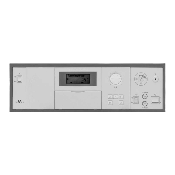
Commissioning Display and control elements A User interface: B Rotary selector "ts" for "stan- Central heating time pro- dard room temperature" gram C Control thermostat Time program DHW heat- D Excess temperature reset E ON/OFF switch Time program DHW circu- F Fuses lation pump G TEST key... -
Page 40: Changing The Language
Commissioning Changing the language Press the following keys: 2. b for the required language. 1. c press. 3. d to confirm. Testing the high limit safety cut-out The minimum circulation volume 2. Release the "TEST" key. should be 10 % of the circulation volume at rated output. - Page 41 Commissioning Matching the coding addresses to the system . . . (cont.) 4. Set the emissions test switch to 7. Determine the minimum burner out- "a". put (base load) through the fuel consumption. 5. Press K and d simultaneously Record the relevant value. for approx.
-
Page 42: Checking Outputs (Actuators) And Sensors
Commissioning Matching the coding addresses to the system . . . (cont.) 7. Determine the minimum burner 9. Determine the partial output output (base load) through the through the fuel consumption. fuel consumption. Record the relevant value. Record the relevant value. 10. - Page 43 Commissioning Checking outputs (actuators) and sensors (cont.) The following relay outputs can be controlled subject to system design: Display screen Explanation Burner stage 1 ON Burner stage 1 + 2 ON Subject to the setting of coding ad- dress "02" Burner mod., close, ntr.
- Page 44 Commissioning Adjusting the heating curves (cont.) A Heating curve slope for low tem- B Slope of the heating curve for perature heating systems heating systems with a boiler (according to the Energy Savings water temperature in excess of Order [Germany]) 75 C Adjusting the set room temperature The heating curve is offset along the...
- Page 45 Commissioning Adjusting the heating curves (cont.) Standard room temperature Set the "Normal room temp." with rotary selector"ts". The value will be automatically accepted after approx. 2 s. Adjustment of the standard room tem- perature from 20 to 26 °C A Boiler water temperature or flow temperature in °C B Outside temperature in °C C Set room temperature in °C...
- Page 46 Commissioning Adjusting the heating curves (cont.) Reduced room temperature Press the following keys: 1. E for "Red.room temp.". 2. a/b for the selected value. 3. d to confirm. Adjustment of the reduced room tem- perature from 3 to 14 °C A Boiler water temperature or flow temperature in °C B Outside temperature in °C...
- Page 47 (accessories) must be plugged in (see The data transfer via the LON system parts list). can take several minutes. Single boiler system with Vitotronic 200-H and Vitocom 300 Set up the LON subscriber numbers Note and further functions via code 2.
- Page 48 Commissioning Integrating a control unit into the LON (cont.) Boiler control unit Vitotronic 200-H Vitotronic 200-H Vitocom Subscriber no. 1 Subscriber no. 10 Subscriber no. 11 Subscriber Code "77:1" Code "77:10" Set code "77:11" no. 99 Control unit is fault...
- Page 49 Commissioning Integrating a control unit into the LON (cont.) Carrying out a subscriber check In conjunction with LON. Communication with the system devices connected to the fault manager is tested with a subscriber check. Precondition: 2. a/b for the required subscri- The control unit must be pro- ber.
-
Page 50: Service Level Summary
Service scans Service level summary Function Key combination Exit Page Adjusting the dis- Press d and a si- play contrast multaneously; the dis- play darkens Press d and b si- multaneously; the dis- play becomes lighter Updating the LON L and d approx. Press e subscriber list 2 s simultaneously... -
Page 51: Temperatures, Boiler Coding Card And Brief Scans
Service scans Temperatures, boiler coding card and brief scans Press the following keys: 2. a/b for the required scan. 1. K + G simultaneously for 3. d Scanning is completed. approx. 2 s. The following values can be scanned, subject to the actual system equip- ment level: Display Explanation... - Page 52 Service scans Temperatures, boiler coding card and brief . . . (cont.) Brief Display screen scan System design Burner Number (see coding address type of KM "00") 0: single BUS sub- stage scribers 1: two- stage 2: mod. Software Software Software Software version...
-
Page 53: Operating Conditions
Service scans Temperatures, boiler coding card and brief . . . (cont.) Brief Display screen scan Device ID, see coding address "92" in code 2 A4: hexadecimal, 164: decimal Max. demand tempera- ture for heating cir- cuits/DHW cylinder Software version Solar con- trol unit 0: Not avail-... -
Page 54: Resetting Parameters
Service scans Operating conditions (cont.) Display screen Explanation Normal room temp. Set value Room temperature Actual value, if a remote control unit is connected. Solar DHW temp. Actual value in conjunction with a solar heating system. Collector temp. Actual value in conjunction with a solar heating system. -
Page 55: Scanning And Resetting The "Service" Display
Service scans Display "Service" After the limits defaulted via coding Note addresses "1F", "21" and "23" have Set code "24:1" and then code "24:0" been reached, the programming unit if a service is carried out before "Ser- flashes "Service", and the red fault vice"... -
Page 56: Checking And Acknowledging Faults
Troubleshooting Faults that are displayed at the programming unit Fault display layout A Fault display C Fault number B Fault symbol D Fault code The red fault indicator flashes for A central fault messaging facility con- every fault. nected to plug gÖ will be switched "Fault"... -
Page 57: Calling Up Fault Codes From The Fault Memory (Fault History)
Troubleshooting Faults that are displayed at the programming unit (cont.) Calling up acknowledged fault messages Press the following keys: 2. a/b for the acknowledged fault. 1. d approx. 2 s. Plain text fault display Burner Sensor 17A Safety temp. limit Sensor 17B Safety chain Room temperature sensor... - Page 58 Troubleshooting Faults that are displayed at the programming unit (cont.) Fault codes Fault code System character- Cause Measures on the dis- istics play Control mode Service Service the equipment. "0F" is only dis- After the service, set played in the fault coding address "24:0".
- Page 59 Troubleshooting Faults that are displayed at the programming unit (cont.) Fault code System character- Cause Measures on the dis- istics play Cylinder primary Cylinder tempera- Check the cylinder tem- pump "ON": ture sensor 1 lead perature sensor (see Set DHW tempera- broken page 109) ture = Set boiler...
- Page 60 Troubleshooting Faults that are displayed at the programming unit (cont.) Fault code System character- Cause Measures on the dis- istics play Shunt pump con- Temperature sen- Check temperature sen- stantly "ON" sor aJB lead sor (see page 110) With cylinder pri- broken Without temperature mary system:...
- Page 61 Troubleshooting Faults that are displayed at the programming unit (cont.) Fault code System character- Cause Measures on the dis- istics play Control mode Temperature sen- Check solar control unit Only solar control sor lead broken, sensor unit fault codes will Connection at S3 be displayed of the Vitosolic...
- Page 62 Troubleshooting Faults that are displayed at the programming unit (cont.) Fault code System character- Cause Measures on the dis- istics play Control mode Return tempera- Insert plug aJA and ture control con- check coding figuration fault: Code "OC:1" has been selected, but plug aJA is not plugged in and/or...
- Page 63 Troubleshooting Faults that are displayed at the programming unit (cont.) Fault code System character- Cause Measures on the dis- istics play Control mode Incorrect LON Replace LON communi- communication cation module (see module page 107) Boiler cools down External safety Check plug aBÖ...
- Page 64 Troubleshooting Faults that are displayed at the programming unit (cont.) Fault code System character- Cause Measures on the dis- istics play Control mode Communication Check plug-in adaptor fault plug-in (see page 119). adaptor for exter- Without plug-in adaptor: nal safety equip- Set code "94:0"...
- Page 65 01 to 98 Control mode A fault has oc- Download fault code to curred at a sub- subscriber scriber, e.g. 12 (Vitotronic 200-H) Installation and service instruc- no connection to tions of the rele- the subscriber vant control unit Check coding...
-
Page 66: Boiler Water Temperature Control
Function description Boiler water temperature control Brief description The boiler water temperature is In conjunction with Therm-Control: regulated by starting and stopping The set boiler water will be the burner or through modulation. increased when the actual tempera- The set boiler water temperature is ture at the Therm-Control sensor determined from the following para- falls below the set temperature. - Page 67 (e.g. after a weekend shutdown) must be able to be reduced by at least 50 % Also affects the heating circuits of a Vitotronic 200-H installed down- stream Function The Therm-Control sensor, installed near the return connector, captures the return temperature.
- Page 68 Shunt pump sized to approx. 30 % Required coding: "4C:2" of the total throughput Also affects the heating circuits of a Vitotronic 200-H installed down- stream Function The temperature sensors T1 and T2 capture the return temperature at dif- ferent test points.
- Page 69 Function description Boiler water temperature control (cont.) The shunt pump is started via tem- The flow rate will be reduced via the perature sensor T2 if the factory- three-way mixer if, in spite of the rais- selected minimum return temperature ing of the return temperature the mini- (defaulted by the boiler coding card) mum return temperature, captured by...
-
Page 70: Control Sequence
Function description Boiler water temperature control (cont.) ERB80 function Code "04:2" Subject to heat demand, values between 6 and 20 K result. Control sequence Boiler goes cold (set value 2 K) The burner start may be delayed by a The burner start signal is selected as few minutes subject to the number of the set boiler water temperature auxiliary circuits and the combustion... - Page 71 Function description Heating circuit control Brief description The set flow temperature of the sys- The system circuit flow temperature tem circuit (heating circuit A1) is is equal to the boiler water tempera- determined by the following para- ture. meters: Coding addresses that influence Outside temperature the heating circuit control: Set room temperature...
-
Page 72: Heating Circuit Control
Function description Heating circuit control (cont.) DHW temperature With priority control: The set flow temperature will be adjusted to 0 °C whilst the cylinder is being heated up. Without priority control: The heating circuit pump continues to operate with the same set value. Heating circuit pump logic (economy mode) The heating circuit pump is switched OFF (set flow temperature set to... - Page 73 Function description Heating circuit control (cont.) Party and economy keys on all control units have no function. Frost protection In the case of outside temperatures below +1 ºC a minimum flow tempera- ture of 10 ºC is ensured. For changes see coding address "A3", variable frost limit.
- Page 74 Function description Heating circuit control (cont.) Example using the settings in the delivered condition A Heating curve for operation with B Heating curve for operation with standard room temperature reduced room temperature Reducing the heat-up time During the transition from operation The value and duration of the addi- with reduced room temperature to tional increase of the set boiler water...
- Page 75 Function description Heating circuit control (cont.) Example using the settings in the delivered condition A Start of operation with standard C Set boiler water or flow tempera- room temperature ture in accordance with the B Set boiler water or flow tempera- selected coding address "FA": ture in accordance with the 50 °C + 20 % = 60 °C...
- Page 76 Function description Cylinder temperature control Brief description The cylinder temperature controller During cylinder heating, central is a constant temperature controller. heating is switched OFF (optional It acts as the result of starting and cylinder priority). stopping the cylinder primary pump. Coding addresses that influence The switching differential is ±2.5 K.
-
Page 77: Cylinder Temperature Control
Function description Cylinder temperature control (cont.) Frost protection The DHW cylinder will be heated to 20 ºC if the DHW temperature falls below 5 ºC. Auxiliary function for DHW heating This function is activated by default- ing a second set DHW temperature via coding address "58"... - Page 78 Function description Cylinder temperature control (cont.) System with Vitosolic A third set DHW temperature can be Reheating by the boiler will be sup- defaulted via coding address "67". pressed above this value. The DHW cylinder is heated exclusively by the solar heating system.
- Page 79 Function description Cylinder temperature control (cont.) The DHW cylinder goes cold (set The DHW cylinder is hot: value 2.5 K, change via coding The control unit checks whether the address "59"): boiler will be required to supply heat The set boiler water temperature is after the cylinder has been heated adjusted 20 K higher than the set up or whether residual boiler heat...
- Page 80 Function description Cylinder temperature control (cont.) Code "55:3", cylinder temperature control, cylinder primary system The DHW cylinder goes cold (set The DHW cylinder is hot: value 2.5 K, change via coding (Cylinder temperature sensor 1: address "59"): Actual value set value The set boiler water temperature is adjusted 20 K higher than the set Cylinder temperature sensor 2:...
- Page 81 Coding Resetting codes to their delivered condition Press the following keys: 3. d to confirm 1. L + G simultaneously for approx. 2 s. 4. a/b to select "Standard set- ting? No". 2. e "Standard setting? Yes" appears. Code 1 Calling up code 1 Press the following keys: 5.
- Page 82 Coding Code 1 (cont.) Coding in the delivered condition Possible change 03:0 Gas operation 03:1 Oil fired operation (irre- versible) 03:2 This occurs automati- cally, if an incorrect boiler coding card is inserted or none is present Burner (modulating) 05:70 Burner curve 05:0 Linear burner curve...
- Page 83 Coding Code 1 (cont.) Coding in the delivered condition Possible change Min. flow temp. A1 C5:20 Electronic minimum C5:1 Minimum limit adjustable flow temperature limit from 1 to 127 °C 20 °C C5:127 (only enabled during operation with standard room temperature) Max.
- Page 84 Coding Code 2 (cont.) Calling up code 2 Press the following keys: 5. a/b for the selected value. 1. L + G simultaneously for 6. d to confirm; the display approx. 2 s. briefly shows "accepted"; the address 2. d to confirm.
- Page 85 Coding Code 2 (cont.) Coding in the delivered condition Possible change 05:70 Burner curve 05:0 Modulating burner: Linear burner curve 05:1 Non-linear burner curve )·100 05:99 in kW: Partial output at of the servomotor run- time in kW: Maximum output 06:87 Maximum boiler water 06:20...
- Page 86 Coding Code 2 (cont.) Coding in the delivered condition Possible change 14:... Minimum burner run- 14:0 Minimum runtime adjus- time in min table from 0 to 15 min Delivered condition de- 14:15 faulted by the boiler coding card 15:10 Runtime servomotor 15:5 Runtime adjustable from mod.
- Page 87 Coding Code 2 (cont.) Coding in the delivered condition Possible change 23:0 No time interval for 23:1 Interval adjustable from 1 burner service selected to 24 months 23:24 24:0 The service display is 24:1 Service display (address reset set automatically) 26:0 Burner fuel consump- 26:1...
- Page 88 Coding Code 2 (cont.) Coding in the delivered condition Possible change 4C:0 Connection at plug 4C:1 Primary pump cylinder sÖA1: primary system Heating circuit pump 4C:2 Therm-Control contact 4C:3 Circulation pump flue gas/water heat exchan- 4d:1 Connection at plug sL: 4d:2 Boiler circuit pump Shunt pump...
- Page 89 Coding Code 2 (cont.) Coding in the delivered condition Possible change 56:0 Set DHW temperature 56:1 Set DHW temperature adjustable from 10 to adjustable from 10 to 60 °C 95 °C Note Observe the max. per- missible DHW tempera- ture. Change the control ther- mostat "R"...
- Page 90 Coding Code 2 (cont.) Coding in the delivered condition Possible change 64:2 During party mode and 64:0 No DHW heating, after external change- DHW circulation pump over during operation "OFF" with constant standard 64:1 DHW heating and DHW room temperature: circulation pump accord- Enable constant DHW ing to time program...
- Page 91 Coding Code 2 (cont.) Coding in the delivered condition Possible change 72:0 DHW circulation pump: 72:1 "OFF" during DHW heat- "ON" according to time ing to the second set program value 72:2 "ON" during DHW heat- ing to the second set value 73:0 DHW circulation pump:...
- Page 92 Coding Code 2 (cont.) Coding in the delivered condition Possible change 80:6 A fault message is dis- 80:0 Immediate fault message played, providing a fault 80:2 A fault message is issued is active for at least 30 s after a delay, 80:199 adjustable from 10 to 995 s;...
- Page 93 The outside temperature tion module: of the sensor connected The control unit sends to the control unit is only the outside temperature utilised internally to the Vitotronic 200-H 97:1 The control unit receives the outside temperature from the Vitotronic 200-H...
- Page 94 Coding Code 2 (cont.) Coding in the delivered condition Possible change 98:1 Viessmann system 98:1 System number adjusta- number (in conjunction ble from 1 to 5 with monitoring several 98:5 systems via Vitocom 300) 99:0 Connection at terminals 99:8 External blocking...
- Page 95 Coding Code 2 (cont.) Coding in the delivered condition Possible change A3:2 Outside temperature A3: 9 Heating circuit pump below 1 °C: Heating cir- "ON"/"OFF", see the fol- cuit pump "ON" A3:15 lowing table Outside temperature above 3 °C: Heating cir- cuit pump "OFF"...
- Page 96 Coding Code 2 (cont.) Coding in the delivered condition Possible change A4:0 With frost protection A4:1 No frost protection. Adjustment only possible if code "A3: 9" has been selected. Note Observe the information regarding coding address "A3". A5:5 With heating circuit A5:0 Without heating circuit pump logic function...
- Page 97 Coding Code 2 (cont.) Coding in the delivered condition Possible change A6:36 Extended economy A6:5 Extended economy mode mode disabled enabled, i.e. the burner A6:35 and heating circuit pump will be switched OFF at a variable value, adjustable between 5 and 35 °C plus 1 °C.
- Page 98 Coding Code 2 (cont.) Coding in the delivered condition Possible change b5:0 b5:1 Heating circuit pump With remote control logic function, see the fol- Without room tempera- b5:8 lowing table: ture-dependent heating circuit pump logic func- tion Parameter ad- With heating circuit pump logic function: dress b5:...
- Page 99 Coding Code 2 (cont.) Coding in the delivered condition Possible change d5:0 With external heating d5:1 Heating program program changeover: switches to "Constant Heating program central heating with stan- switches to "Constant dard room temperature" central heating with re- duced room tempera- ture"...
- Page 100 Coding Code 2 (cont.) Coding in the delivered condition Possible change Fb:30 Duration for raising the Fb:0 Duration adjustable from set boiler water tem- 0 to 300 min; perature or the set flow Fb:150 1 step 2 min temperature (see cod- ing address "FA") 60 min.
-
Page 101: Connection And Wiring Diagram
Designs Connection and wiring diagram Overview Main PCB low voltage Boiler coding card Main PCB 230 V A10 LON communication module Programming unit (accessories) Optolink PCB/emissions test A11 Power supply unit PCB switch A12 Boiler control section Electronics PCB Electrical interfaces... - Page 102 Designs Connection and wiring diagram (cont.) Main PCB low voltage Outside temperature sensor/ aJB Return temperature sensor T2 radio clock receiver § Boiler water temperature sen- Temperature sensor cylinder primary system Cylinder temperature sensor/ External hook-up cylinder temperature sensor 2 KM BUS subscriber for a cylinder primary system External hook-up...
- Page 103 Designs Connection and wiring diagram (cont.) Main PCB 230 V...
- Page 104 Designs Connection and wiring diagram (cont.) sÖ Heating circuit pump lÖ Burner stage 2/modulating aBÖ External connections Primary pump cylinder pri- (remove jumper when con- mary system necting) a External safety equip- Circulation pump flue gas/ ment water heat exchanger b External blocking Safety chain (zero volt) Switching output...
-
Page 105: Components From The Parts List
Components Components from the parts list Main PCB 230 V Relays and outputs for controlling pumps, servomotors and the burner Slot for power supply PCB and boil- er control section Main PCB low voltage Connection plug for sensors, com- munication connections and exter- nal hook-ups Slots for electronics PCB, power supply PCB, LON communication... -
Page 106: Programming Unit
Components Components from the parts list (cont.) The following functions are triggered in position "h": Burner stop (may be delayed through fuel oil preheating or Vitoair draught stabiliser) Starting all pumps Boiler water temperature regulated by control thermostat "R" Programming unit Settings: Time Heating program... -
Page 107: High Limit Safety Cut-Out
Components Components from the parts list (cont.) LON communication module Plug the module into the control unit. The communication interruption will be displayed (see page 64). A Control unit or Vitocom 300 B Connecting cable, part no. 7143 C Terminator, part no. 7143 497 TEST key For testing the high limit safety cut- out. - Page 108 Components Components from the parts list (cont.) Control thermostat In the delivered condition set to Controls the maximum boiler water 95 °C; may be changed to 100 ºC temperature (e.g. in emissions test mode) Note 6 mm setting axis (flattened), selec- Adjust downwards at least 20 K tor button pushed onto the front of higher than the DHW temperature,...
- Page 109 Components Components from the parts list (cont.) Boiler water temperature sensor and cylinder temperature sensor Connection See chapter "Connecting sensors". Check sensor 1. Pull plug § or %. 2. Check the sensor resistance at terminals "1" and "2" or "2" and "3" of the plug (if a second cylinder temperature sensor has been con- nected).
- Page 110 Components Components from the parts list (cont.) Contact temperature sensor and immersion temperature sensor For capturing the flow or return temperature Connection See chapter "Connecting sensors". Check sensor 1. Pull plug ? or aJ. 2. Check the sensor resistance across plug terminals "1" and "2". 3.
-
Page 111: Outside Temperature Sensor
Components Components from the parts list (cont.) Outside temperature sensor Connection See chapter "Connecting sensors". Check outside temperature sensor 1. Pull plug !. 2. Check the sensor resistance across plug terminals "1" and "2". 3. Disconnect conductors from the sensor, if the actual values deviate severely from the curve, repeat the sensor test and compare with the actual temperature (for scanning,... - Page 112 Components Radio clock receiver, part no. 7450 563 (cont.) A Outside temperature sensor D Red LED B Radio clock receiver E Aerial C Green LED Connection 2-core lead, up to 35 m long with a cross-section of 1.5 mm Check reception During reception, the green LED on If the red LED flashes, rotate the aer- the radio clock receiver flashes.
- Page 113 Components Radio clock receiver, part no. 7450 563 (cont.) Specification Protection IP 43 Permissible ambi- ent temperature during operation, storage and 40 to + 70 °C transport Flue gas temperature sensor, part no. 7450 630 The sensor monitors the selected limit value (see coding address "1F"). Connection See chapter "Connecting sensors".
-
Page 114: Specification
Components Flue gas temperature sensor, part no. 7450 630 (cont.) Checking the flue gas temperature sensor 1. Pull plug aG. 2. Check the sensor resistance across plug terminals "1" and "2". 3. Compare the measurement with the actual temperature displayed (for scanning, see chapter "tempera- tures, boiler coding card and brief scans"). -
Page 115: Remote Control
Components Remote control Vitotrol 200, part no. 7450 017 With integral room temperature sensor. Settings Day temperature Heating program Economy and party mode Function changes Changes can be made via the follow- "A0", "b0" and "E1" (see chapter ing coding addresses: "Code 2"). - Page 116 Components Remote control (cont.) Coding Never adjust DIP switch S6. D PCB DIP switches (back of the casing top) Specification during opera- 0 to + 40 °C tion Power supply via KM BUS. during storage Power consump- and transport 20 to + 65 °C tion 0.2 W Setting range for...
- Page 117 Components Remote control (cont.) Function changes Changes can be made via the follow- "A0", "b0" and "E1" (see chapter ing coding addresses: "Code 2"). Connection A Wall mounting fixture for Vitotrol B To the control unit or to the KM BUS distributor...
-
Page 118: Boiler Coding Card
Components Remote control (cont.) Coding Never adjust DIP switch S3. D PCB DIP switches (back of the casing top) Specification during opera- 0 to + 40 °C tion Power supply via KM BUS. during storage Power consump- and transport 20 to + 65 °C tion 0.5 W Setting range for... - Page 119 Components Function extension 0 - 10 V, part no. 7174 718 (cont.) fÖ Power supply aBJ zero volt contact aVF 0 - 10 V input Main isolator (if required) aVG KM BUS DIP switch (see table) DIP switch Function Reduced mode, heating circuit A1 0 - 100 °C 30 to 120 °C Note...
- Page 120 Components Plug-in adaptor for external safety equipment, part . . . (cont.) Upper part of the plug-in adaptor The plug-in adaptor is automatically recognised by the control unit as a KM BUS subscriber. Any central fault message module connected to plug gÖ (230 V~) will also be switched ON.
- Page 121 Components Plug-in adaptor for external safety equipment, part . . . (cont.) Lower part of the plug-in adaptor A Wiring chamber C Controlled external shutdown B External safety equipment D PlugaBÖ X1 Additional high limit safety E Plug aBÖ of the control unit cut-out F To the control panel or to the mes- saging facility...
- Page 122 Components Plug-in adaptor for external safety equipment, part . . . (cont.) Remove the jumper in plug aBÖ Note when connecting the external safety Every socket "X1", "X2", "X3" and equipment. "X7" must contain a plug aBÖ. When connecting a motorised flue gas damper, insert plug aBÖ...
-
Page 123: Function Check
Components Secondary air device Vitoair, part no. 7338 725, . . . (cont.) Function check Press the rotary selector at the motor and simultaneously turn it to its cen- tral position. Enable burner from the control unit The rotary selector should turn towards "3". -
Page 124: Parts Lists
Parts lists Parts lists When ordering spare parts 043 Cylinder temperature sensor with Quote the part and serial no. (see plug % type plate A) and the item no. of the 047 LON communication module required part (as per this parts list). 049 Main PCB low voltage Obtain standard parts from your local 050 Electronics PCB... - Page 125 Parts lists Parts lists (cont.)
- Page 126 Parts lists Parts lists (cont.)
- Page 127 Specification Specification Rated voltage 230 V Rated frequency 50 Hz Rated current 2 x 6 A Power consumption 10 W Protection class Protection IP 20 D to EN 60529, safe- guard through appropriate design and installation Function Type 1 B to EN 60730-1 Permiss.
- Page 128 Keyword index Keyword index AC burner Calling up fault messages ........
- Page 129 Keyword index Keyword index (cont.) Delivered condition Fault codes, summary ........Device ID Fault display .
- Page 130 Keyword index Keyword index (cont.) Immersion temperature sensor 15, 16, 105 ........Indicator (diode) PCBs .
- Page 131 Shunt pump 7, 8 Vitotronic 200-H ............
- Page 132 Applicability Vitotronic 200, type GW1 Only for integration/installation in/on Viessmann boilers. Valid for control units: Part no. 7248 084 Viessmann Werke GmbH&Co KG Viessmann Limited D-35107 Allendorf Hortonwood 30, Telford Telephone: +49 6452 70-0 Shropshire, TF1 7YP, GB Fax: +49 6452 70-2780 Telephone: +44 1952 675000 www.viessmann.com...