Viessmann VITOTRONIC 200 Operating Instructions Manual
Heating system and domestic ventilation system with heat pump control unit
vitotronic 200, type wo1c
Hide thumbs
Also See for VITOTRONIC 200:
- Service instructions manual (336 pages) ,
- Installation and service instructions for contractors (136 pages) ,
- Installation and service instructions manual (132 pages)

Related Manuals for Viessmann VITOTRONIC 200


Summary of Contents for Viessmann VITOTRONIC 200
-
Page 1: Operating Instructions
VIESMANN Operating instructions for the system user Heating system and domestic ventilation system with heat pump control unit Vitotronic 200, type WO1C VITOTRONIC 200 Please keep safe. 5623 540 GB 8/2012... -
Page 2: Safety Instructions
Safety instructions For your safety Please follow these safety instructions closely to Installation conditions prevent accidents and material losses. Please note Safety instructions explained Incorrect ambient conditions can lead to system damage and can put safe operation at risk. Danger This symbol warns against the risk of injury. -
Page 3: Table Of Contents
Index Index 1. Introductory information Commissioning ..................Terminology ................... Your system is preset at the factory ............Energy saving tips ................. Tips for greater comfort ................. 2. About the controls Opening the control unit ................. Programming unit .................. "Operating info" ................... 10 ■... - Page 4 Index Index DHW heating outside the time program ..........28 Activating "1x DHW heating" .............. 28 ■ Stopping DHW heating ................28 6. Heating system with elec- ........................29 tric booster heater 7. Active cooling mode Enabling and blocking active cooling mode ........... 30 8.
- Page 5 Index Index (cont.) "Power-OFF C5" is displayed ..............47 "Controls locked out" is displayed ............47 "Check filter" is displayed ..............47 Doors/windows can only be opened with difficulty ......... 47 Doors/windows bang when opened ............48 16. Maintenance Cleaning the heating system ..............49 In conjunction with a brine/water or water/water heat pump ....
-
Page 6: Introductory Information Commissioning
Introductory information Commissioning The commissioning and matching up of the heat pump Note control unit to local conditions and to the structural These operating instructions also describe functions characteristics of the building, plus the instruction of that are only available on some heat pump models or the user in operating the system, must be carried out only with accessories. -
Page 7: Energy Saving Tips
Introductory information Energy saving tips Central heating/Central cooling Thermostatic valves: ■ Ensure that thermostatic valves are set correctly. Standard room temperature ("Set room tempera- Radiators: ■ ■ ture", see page 20): Never place things in front of radiators or thermo- Never overheat your home. - Page 8 Introductory information Tips for greater comfort (cont.) Heating curve/cooling curve (see page 22): ■ The heating curve enables you to individually adjust the heating system to the actual heat demand in your home. If set correctly, your preferred temperature will be achieved all year round.
-
Page 9: Programming Unit
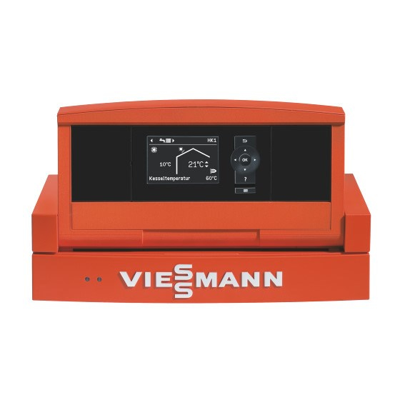
About the controls Opening the control unit The heat pump control unit may look different depend- ing on the type of heat pump. Control unit at the front of the heat pump 21°C 14°C Fig. 1 Control unit on top of the heat pump Control unit mounted on the wall Fig. -
Page 10: Operating Info
About the controls Programming unit (cont.) 21 °C 14 °C Fig. 4 Takes you to the previous step in the menu or OK Confirms your selection or saves the setting. cancels a setting you have started to input. Calls up "Operating info" (see following chapter) Cursor keys or additional information on the selected menu. -
Page 11: Standard Menu
About the controls Programming unit (cont.) Preheater bank for the ventilation unit is active, if Messages: installed. Symbol using fan stage 2 as an exam- Fault Warning Ventilation unit was switched off at the ON/OFF Note switch Standard menu In the standard menu, you can make and call up the How to call up the standard menu: following settings for the preferred heating/cooling cir- If the screen saver is active (see page 12):... -
Page 12: Extended Menu
About the controls Extended menu In the extended menu, you can adjust and call up all Note settings from the heat pump control unit's range of Your heating contractor can block the operation of the functions, such as inputting settings for the holiday extended menu. -
Page 13: Operating Program
About the controls How to use the controls (cont.) 21 °C 14 °C Flow temperature 40 °C Menu Heating/cooling System Manual mode Continue with Heating circuit 1 Ù Ú Htg circuit selection Ù Ú Ù Ú Party mode ê Ú Economy mode ê... - Page 14 About the controls Operating program (cont.) Heating/cooling System version with DHW heating System version without DHW heating circuits Symbol Operating program Symbol Operating program Separate cooling "Standby mode" "Standby mode" circuit "Only DHW" — — "SKK" "Cooling and DHW" "Coolng" (Factory setting) Symbol Operating program...
-
Page 15: Operating Programs For Ventilation
About the controls Operating program (cont.) Operating programs for ventilation Operating program Operating status Air flow rate Ventilation stage "Standby mode" No ventilation — "Standard operation" Minimum air flow rate — "Ventilation program" "Reduced" Reduced air flow rate "Standard" Standard air flow rate "Intensive"... -
Page 16: Example
About the controls Time program (cont.) The individual operating status is displayed by bars ■ of different heights on the time chart. Where several time phases overlap, the operating status with the highest bar takes priority. In the extended menu, you can call up the time pro- ■... -
Page 17: Setting The Time Program Efficiently
About the controls Time program (cont.) Setting the time program efficiently Example: You want to set the same time program for every day except Monday: 1. Select the "Monday Sunday" part of the week and – input the time program settings. Heating time program Monday-Sunday ê... -
Page 18: Start-Up/Shutdown Starting The Heat Pump
Start-up/shutdown Starting the heat pump The heat pump control unit may look different depend- ing on the type of heat pump. Control unit at the front of the heat pump 21°C 14°C Fig. 14 Fault indicator (red) ON indicator (green) ON/OFF switch Control unit on the heat pump Fig. -
Page 19: Stopping The Heat Pump
Start-up/shutdown Starting the heat pump (cont.) After a short time, the standard menu is displayed (see page 11) and the green ON indicator illumi- nates. Your heat pump and, if installed, your remote control units are now ready for operation. Stopping the heat pump With frost protection Select the operating program "Standby mode"... -
Page 20: Setting The Reduced Room Temperature For Heating/Cooling
Central heating/central cooling Room temperature Further information can be found in chapter "Terminology" in the appendix. Setting the standard room temperature for heating/cooling Factory setting: 20 °C 4. "Set room temperature" 5. Set the required value. For the priority heating/cooling circuit Note Standard menu 1. -
Page 21: Time Program
Central heating/central cooling Time program Further information can be found in chapter "Terminology" in the appendix. Setting the time program for heating/cooling Factory setting: One time phase from 00:00 to 24:00 h Operating status for heating/cooling for every day of the week with the operating status "Standard". -
Page 22: Heating Curve/Cooling Curve
Central heating/central cooling Heating system with heating water buffer… (cont.) Note "Fixd value" ■ Between the time phases, the heating water buffer The entire volume in the heating water buffer cylin- ■ cylinder is not heated; only the frost protection for the der is charged to a fixed temperature. -
Page 23: Switching Off Central Heating/Central Cooling
Central heating/central cooling Switching off central heating/central cooling For the priority heating/cooling circuit 3. If necessary, press / for the required heating/cool- ing circuit. Standard menu 4. "Operating program" 1. / for the operating program: "Only DHW" (no central heating/central cooling) ■... -
Page 24: Energy Saving Function "Economy Mode
Central heating/central cooling Energy saving function "Economy mode" Setting "Economy mode" for heating Extended menu Note The display of the set room temperature does not ■ 2. "Heating" or "Heating/cooling" change. 3. If necessary, / for the required heating/cooling cir- In "Economy mode", cooling via a heating/cooling ■... -
Page 25: Cancelling Or Deleting The "Holiday Program
Central heating/central cooling Energy saving function "Holiday program" (cont.) Central cooling: Display in the extended menu ■ No cooling via any heating/cooling circuit. A separate cooling circuit continues to be cooled. In the extended menu, you can call up the set holiday DHW heating: program under "Information"... -
Page 26: Dhw Heating Dhw Temperatures
DHW heating DHW temperatures Setting the standard DHW temperature Factory setting: 50 °C 3. "Set DHW temperature" 4. Set the required value. Extended menu 2. "DHW" Setting the higher DHW temperature Factory setting: 60 °C Extended menu The DHW will be heated to the higher DHW tempera- 2. -
Page 27: Setting The Start Optimisation
DHW heating Time program (cont.) 3. "Time program DHW" Special feature with operating status "Standard" 4. Set the required time phases and operating status. and "Temp. 2" Procedure for setting a time program, see page 15. With the following system versions, the entire volume Note of the DHW cylinder is heated: Between the time phases, DHW is not heated;... -
Page 28: Dhw Heating Outside The Time Program
DHW heating Time program (cont.) Operating status for the DHW circulation pump "5/25 cycls" ■ The DHW circulation pump starts twice per hour for 5 min (25 min pause). "5/10 cycls" ■ The DHW circulation pump starts four times per hour for 5 min (10 min pause). -
Page 29: Heating System With Elec
Heating system with electric booster heater Heating system with electric booster heater Note Further information can be found in chapter Constant operation of an electric booster heater results "Terminology" in the appendix. in high electricity consumption. Enabling or blocking the electric booster heater for central heating Factory setting: Locked Extended menu 2. -
Page 30: Enabling And Blocking Active Cooling Mode
Active cooling mode Enabling and blocking active cooling mode Further information can be found in chapter "Terminology" in the appendix. Note The cooling function must be set by your heating ■ contractor. Constant operation of active cooling mode results in ■... -
Page 31: System
Air/water heat pumps Air/water heat pumps Setting the time program for quieter operation Further information can be found in chapter "Terminology" in the appendix. Factory setting: No time phase from 00:00 to 24:00 h for every day of the week. The fan runs at full speed (100 %) when there is a heat demand. -
Page 32: Starting Ventilation
Ventilation Starting ventilation Display in the standard menu Further information can be found in chapter "Terminology" in the appendix. The ventilation unit is switched on by your heating con- tractor during commissioning (for the position of the 21 °C 14 °C ON/OFF switch, see chapter "Filter change"... -
Page 33: Setting The Operating Program For Ventilation
Ventilation Operating program (cont.) Setting the operating program for ventilation Extended menu 2. "Ventilation" 3. "Operating program" 4. For example "Ventilation program" For further possible operating programs, see page 15. Ventilation without heat recovery Further information can be found in chapter "Terminology"... -
Page 34: Comfort Function "Intensive Operation
Ventilation Time program (cont.) Extended menu: "Standard" ( ■ Standard air flow rate (nominal air flow rate). 2. "Ventilation" If a humidity and/or CO sensor is installed in your 3. "Time prog ventilation" home, then the air flow rate will be adjusted accord- 4. -
Page 35: Ending "Economy Mode
Ventilation Energy saving function "Economy mode" (cont.) Ending "Economy mode" Automatically on changeover to operation with mini- ■ mum air flow rate ( ) in accordance with the time program. That is, between the selected time phases. Set "Economy mode" to "OFF". ■... -
Page 36: Own Consumption Of Power
Power from a photovoltaic system Own consumption of power Further information can be found in chapter "Terminology" in the appendix. Components that may be enabled for consumption Requirements of power on site DHW cylinder You would like to heat the DHW cylinder to a higher DHW heating must be switched ON (operating program ■... -
Page 37: Setting The Display Contrast
Further adjustments Setting the display contrast Extended menu 3. "Contrast" 4. Set the required contrast. 2. "Settings" Setting the display brightness If you would like the texts in the menu to be more 3. "Brightness" clearly legible, change the brightness for "Control". 4. -
Page 38: Setting The Preferred Heating/Cooling Circuit For The Standard Menu
Further adjustments Setting the preferred heating/cooling circuit for the standard menu Advanced menu 2. "Settings" 3. "Standard menu" 4. Select the heating/cooling circuit: "Heating circuit 1" (for heating circuit 1 or heat- ■ ing/cooling circuit 1) Display "HC1" "Heating circuit 2" (for heating circuit 2 or heat- ■... -
Page 39: System
Further adjustments Restoring factory settings (cont.) System setting Settings and values that are reset "System" Time program for the heating water buffer cylinder. ■ Electric booster heater is blocked for central heating. ■ Time program for electric booster heater. ■ "DHW"... -
Page 40: Calling Up Information
Calling up Calling up information You can call up current temperatures, set values, time Detailed call-up options for the individual groups can programs and operating states. be found in chapter "Extended menu overview" see (page 54). The extended menu splits the information into groups: "System"... -
Page 41: Calling Up Messages
Calling up Calling up information (cont.) The central heating will operate in accordance with a Remaining duration of screed drying ■ set time program. Your settings for central heating/ central cooling have no effect for the duration of Screed drying lasts up to 32 days. The value displayed screed drying. -
Page 42: System
Calling up Calling up messages (cont.) 1. Pressing OK provides you with additional informa- Note tion regarding the displayed message. If you have connected signalling equipment for fault ■ messages (e.g. a buzzer), this will be deactivated Note when the fault message is acknowledged. Outside temp. -
Page 43: Manual Mode
Manual mode Manual mode In manual mode, central heating and DHW heating operate independently of the time programs: Unregulated heating with a set flow temperature of ■ 45 °C. DHW heating with "Set DHW temperature 2" (see ■ page 26). No cooling. -
Page 44: Special System Versions
Special system versions Special system versions Further information can be found in chapter "Terminology" in the appendix. The displays in the standard menu and the extended menu differ depending on the system version. At both control levels, only those functions that are rel- evant for your system version are available to you. -
Page 45: Rooms Are Too Cold
What to do if... Rooms are too cold Cause Remedy The heat pump is switched off. Switch the ON/OFF switch ON (see diagrams from ■ page 18). Switch ON the mains isolator (if installed, outside the ■ boiler room). Reset the MCB in the power distribution board (main ■... -
Page 46: Rooms Are Too Hot
What to do if... Rooms are too hot Cause Remedy Heat pump control unit set incorrectly Central heating/central cooling must be enabled. ■ Remote control (if installed) set incorrectly. ■ Check settings and correct if required: Separate operating instructions Operating program (see page 20) ■... -
Page 47: Is Flashing And "Note" Is Displayed
What to do if... " " is flashing and "Note" is displayed Cause Remedy Reference to a special event or operating state of the Proceed as described on page 41. heat pump or heating system. " " is flashing and "Warning" is displayed Cause Remedy Warning due to a specific event or operating state of... -
Page 48: Doors/Windows Bang When Opened
What to do if... Doors/windows bang when opened Cause Remedy In highly airtight buildings, for example a passive Inform your local heating contractor. house: Air flow rates of your ventilation unit for supply air and extract air are out of balance. -
Page 49: In Conjunction With A Brine/Water Or Water/Water Heat Pump
Maintenance Cleaning the heating system In conjunction with a brine/water or water/water heat pump You may clean the appliance with a commercially available domestic cleaning agent (non-scouring). In conjunction with an air/water heat pump Please note Commercially available domestic cleaning agents and special cleaning agents for evapora- tors can damage the heat pump. -
Page 50: Potable Water Filter (If Installed)
If connecting cables of the appliance or externally installed accessories are damaged, replace them with special connecting cables. Replace only with Viessmann cables. Notify your heating contractor accordingly. Cleaning the domestic ventilation system The casing of the ventilation unit may be cleaned with... -
Page 51: Replacing Filters In The Extract Air Valves
Maintenance Cleaning the domestic ventilation system (cont.) Note If required replace the filters, see next chapter. ■ Never alter the setting of annular gap ■ Replacing filters in the extract air valves Note Replace filters if one of the following conditions applies: The heat pump control unit displays "Check filters". - Page 52 Maintenance Replacing the ventilation unit filters (cont.) Remove the left or right side panel Fig. 48...
-
Page 53: Resetting The Service Display
Maintenance Replacing the ventilation unit filters (cont.) Replace filter Fig. 49 Extract air filter Outdoor air filter Resetting the service display 1. Start the ventilation unit after changing the filters. Please note Dust deposits in the appliance can result in malfunctions Never start the appliance without supply air and extract air filters. -
Page 54: Appendix Refrigerant
Appendix Refrigerant This heat pump contains fluorinated hydrocarbons The refrigerants used have the following global warm- (refrigerant) included in the Kyoto Protocol. ing potential: The type plate indicates the type of refrigerant used in R 134A: 1300 ■ the heat pump. R 410A: 1890 ■... - Page 55 Appendix Calling up options under "Information" (cont.) System Heating circuit 1, 2, 3 (HC1/HC2/HC3) "Outside temperature" "Operating program" "Heating and DHW" ■ "Common flow temp" "Only DHW" ■ "Operating status system" "Standby mode" ■ "Time prog. noise red." "Party mode" ■...
- Page 56 Appendix Calling up options under "Information" (cont.) Cooling circuit SKK Ventilation "Operating program" "Operating program" "Cooling and DHW" "Ventilation program" ■ ■ "Only DHW" "Standard operation" ■ ■ "Standby mode" "Standby mode" ■ ■ "Operating status" "Intensive operation" ■ "Standby" "Economy mode"...
-
Page 57: Terminology
Appendix Calling up options under "Information" (cont.) Heat pump "Compressor" "Primary pump/Fan" "Secondary pump" "Valve heating/DHW" "Hours run compressor" "No. of starts comprssr" "Inst.water heater st.1" "Inst.water heater st.1" "Inst.water heater st.2" "Inst.water heater st.2" "SPF heating" "SPF DHW" "SPF overall" "SPF cooling"... -
Page 58: Electric Booster Heater
Appendix Terminology (cont.) At the next period of demand according to the time program the required water temperature will then ide- ally be available, i.e. the heat pump will only need to reheat a little, if at all. Electric booster heater If the required room temperature or DHW temperature Note cannot be achieved with the heat pump alone, an elec-... -
Page 59: Heating Curve/Cooling Curve
Appendix Terminology (cont.) Note Weather-compensated heating mode/cooling mode In reduced heating mode, cooling is disabled. In weather-compensated mode, the flow temperature Room temperature-dependent heating mode/cool- is controlled according to the outside temperature. This ing mode means that only that amount of heat or cold is gener- ated that is actually required to heat or cool the interior In room temperature-dependent mode, a room will be to the room temperature specified by you. - Page 60 Appendix Terminology (cont.) Cooling curve Outside temperature in °C 1.4 1.6 1.8 2.0 2.2 Cooling curve slope Fig. 52 Setting the slope and level using the heating curve as an example The illustrated heating curves apply with the following settings: Heating curve level = 0 ■...
-
Page 61: Heating/Cooling Circuits
Appendix Terminology (cont.) Factory settings: Slope = 0.6 and level = 0. Outside temperature in °C Fig. 54 Changing the slope: The gradient of the heating curves changes. Changing the level: The heating curves are shifted in parallel in a verti- cal direction. -
Page 62: Heating Circuit Pump
Appendix Terminology (cont.) Only one cooling circuit is possible: Example: Heating/cooling circuit "Heating circuit 1" is the heating circuit for the ■ ■ Cooling operation via one heating circuit, e.g. a room rooms occupied by you. with underfloor heating. This room can be cooled in "Heating circuit 2"... - Page 63 Appendix Terminology (cont.) Ventilation unit function Air flow To ensure that your interior suffers neither from nega- tive nor positive pressure, the air flow rate of the sup- ply air must be exactly the same as that of the extract air.
-
Page 64: Cooling Mode
Appendix Terminology (cont.) Cooling mode See "Heating mode/cooling mode". Cooling function The natural cooling and active cooling functions are Air/water heat pumps: supported depending on the heat pump type and the "Natural cooling" ■ installed accessories. Not available. "Active cooling" ■... -
Page 65: Mixer
Appendix Terminology (cont.) Mixer A mixer mixes the heated heating water with the When cooling via a heating circuit, e.g. an underfloor cooled water returning from the heating circuit. The heating system, the mixer serves to keep the tempera- water, heated to the right temperature in line with ture above the condensation point of the indoor air demand, is pumped to the heating circuit by the heat- (dew point). -
Page 66: Compressor
Appendix Terminology (cont.) Compressor Central assembly of a heat pump. The compressor rai- ses the refrigerant to the temperature level required for the heating mode. Weather-compensated heating/cooling mode See "Heating mode/cooling mode". Domestic ventilation See "Controlled domestic ventilation". Time program The time programs are used to specify how your heat- For example, the operating states for central heating ing system should operate at a given time. -
Page 67: Keyword Index
Keyword index Keyword index Comfort function Absence – Intensive operation..........34 – Heating..............7 – Party mode..............23 – Ventilation..............7 Commissioning............6, 19 Acknowledging Compressor..............66 – Note, warning/fault message........41 Contrast, setting............37 Active cooling mode Controlled domestic ventilation – Comfort..............7 – Explanation............. 62 –... - Page 68 Keyword index Keyword index (cont.) DHW heating Energy saving (tips)............. 7 – Comfort..............8 Energy saving function – Energy saving............7 – Economy mode, heating......... 24 – Factory setting............6 – Economy mode, ventilation........34 – Once-only..............8 – Holiday program..........24, 35 –...
- Page 69 Keyword index Keyword index (cont.) Heating mode – Explanation............58, 65 Maintenance...............49 – Reduced..............20 – DHW cylinder............49 – Standard..............20 – Heating system............49 Heating system Maintenance contract..........49 – Cleaning..............49 Manual mode............. 43 – Maintaining..............49 Max. flow temperature, heating........21 Heating water buffer cylinder Max.
- Page 70 Keyword index Keyword index (cont.) Operating status Reduced room temperature......... 20, 65 – DHW circulation pump..........28 Refrigerant..............54 – DHW heating............27 Remaining duration, screed drying......41 – Electric booster heater..........29 Remote control.............9 – Explanation............57, 66 Reset................38 – Heating/cooling............21 Rooms –...
- Page 71 Keyword index Keyword index (cont.) Slope, heating curve/cooling curve......22 Slope/level, heating curve/cooling curve....59 Temperature Solar – Calling up..............40 – Information.............. 40 – DHW................26 – Solar energy yield........... 40 – Heating/cooling, adjusting........20 Solar circuit pump............10 – Own power consumption.........36 Solar thermal system..........
- Page 72 Ventilation heating circuit........32, 63 Your contact Contact your local contractor if you have any questions regarding the maintenance and repair of your system. You may, for example, find local contractors on the internet under www.viessmann.com. Viessmann Werke GmbH&Co KG Viessmann Limited...