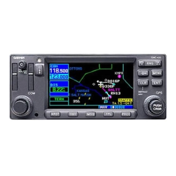
Garmin GNC 420 Pilot's Manual & Reference
Garmin gnc 420: user guide
Hide thumbs
Also See for GNC 420:
- Maintenance manual (168 pages) ,
- Installation manual (136 pages) ,
- Pilot's manual addendum (27 pages)
Table of Contents
Advertisement
Quick Links
Advertisement
Table of Contents

Related Manuals for Garmin GNC 420


Summary of Contents for Garmin GNC 420
- Page 1 GNC 420/420A P i l o t ’ s G u i d e a n d R e f e r e n c e...
-
Page 3: Foreword
Garmin International, Inc., 1200 E. 151st Street, Olathe, Kansas 66062 USA Tel: 913/397.8200 Fax: 913/397.8282 Garmin (Europe) Ltd., Unit 5, The Quadrangle, Abbey Park, Romsey, Hampshire S051 9DL, UK Tel: 44/1794.519944 Fax: 44/1794.519222 Garmin (Asia) Corp., No. 68, Jangshu 2 Road, Shijr, Taipei County, Taiwan Tel: 886/2.2642.9199... - Page 4 Garmin GNC 420 is a precision electronic NAVigation AID (NAVAID), any NAVAID can be misused or misinterpreted and therefore become unsafe. Use the GNC 420 at your own risk. To reduce the risk of unsafe operation, care- fully review and understand all aspects of this Owner’s Manual and the Flight Manual Supplement, and thoroughly practice basic operation prior to actual use.
- Page 5 GNC 420. After installation, the NavData® card will already be installed into the cor- rect slot on the front of the unit (see Appendix A). The GNC 420 will be secured in the installation rack with the proper wiring connections performed. Have your dealer answer any questions you may have about the installation—such as location of antennas or any...
- Page 6 This Garmin product is warranted to be free from defects in materials and workman- ship for one year from the date of purchase. Within this period, Garmin will at its sole option, repair or replace any components that fail in normal use. Such repairs or replace- ment will be made at no charge to the customer for parts or labor, provided the customer shall be responsible for any transportation costs.
-
Page 7: Table Of Contents
PART TWO: REFERENCE Section 1: Communicating with the GNC 420 ......21 COM frequencies Active and standby frequencies Section 2: NAV Page Group (GPS navigation) . -
Page 8: Table Of Contents
INTRODUCTION Table of Contents To quickly and easily locate information on specific tasks, please refer to the Index on page 173. Section 6: WPT Page Group (Waypoint/database information) ....86 Finding and viewing airport location, runway and frequency data Finding and viewing navaid information Creating user-defined waypoints... -
Page 9: Takeoff Tour
Key and Knob Functions The GNC 420 is designed to make operation as simple as possible. The key and knob descriptions on the next three pages provide a general overview of the primary function(s) for each key and knob. This Takeoff Tour section is intended to provide a brief overview of the primary functions of your GNC 420. - Page 10 This will greatly reduce the amount of time spent operating the GNC 420 in flight. The menu key displays a context-sensitive list of options. This options list allows you to access additional features or make settings changes which relate to the currently displayed page.
-
Page 11: Bottom Row Keys
TAKEOFF TOUR Key and Knob Functions Whenever the GNC 420 is displaying a list of information that is too long for the display screen, a scroll bar will appear along the right-hand side of the display. The scroll bar graphically indicates the number of additional items available within the selected category. - Page 12 GNC 420. Prior to using your GNC 420 for the fi rst time, we recommend that you taxi to a location that is well away from buildings and other aircraft so the unit can collect satellite data without interruption.
- Page 13 Check CDI/HSI, RMI and other instruments to verify these indications. Should match current OBS course selection Once the database has been acknowledged, the instrument panel self-test page will appear. Check for the following indications on other instruments: • Course deviation - half left / no flag •...
- Page 14 fi x will be determined. Following the fi rst-time use of your GNC 420, the time required for position fi x will vary - usually from one to two minutes.
- Page 15 (if one is connected). If the GNC 420 has not been operated for a period of six months or more, it may have to ‘Search the Sky’ to collect new data. This means the unit is acquiring satellite data to establish almanac and satellite orbit information, which can take 5 to 10 minutes.
- Page 16 While the GNC 420 is acquiring a position, let’s take a minute to dial in the active and standby frequencies you’ll be using for the fi rst phase of your fl ight. The GNC 420’s display is divided into separate ‘windows’ (or screen areas), including a COM window, data fi...
- Page 17 After the GNC 420 acquires satellites and computes a position, the map page appears automatically. The map page displays your present position (using an airplane symbol) relative to nearby airports, VORs, NDBs, intersections, user waypoints and airspace boundaries— and your route is displayed as a solid line. Data fi elds for destination waypoint (WPT), distance to waypoint (DIS), desired track (DTK) and ground speed (GS) appear on the right hand side of the display.
- Page 18 To select a different page within the group, rotate the small right knob ( *Seven NAV Pages are available when the GNC 420 installation includes connection to traffic and/or weather information sources. See 400 Series Pilot’s Guide Addendum, part number 190-00140-10.
-
Page 19: Aux Group
(Small right knob to select pages within the group) NAV Group NAVCOM Default NAV WPT Group Airport Location Airport Runway Airport Frequency Airport Approach Airport Arrival AUX Group Flight Planning Utility Setup 1 NRST Group Nearest Airport Nearest Nearest NDB Intersection Selection of any main page is performed using the large page group: NAV, WPT, AUX, or NRST. - Page 20 Waypoint Identifier Field The GNC 420 can use direct point-to-point navigation to guide you from takeoff to touchdown, even in the IFR environment. Once a destination is selected, the unit will provide speed, course and distance data based upon a direct course from your pres- ent position to your destination.
- Page 21 To display the frequency list for the desired flight plan or direct-to airport: 1. Push the small right knob ( ) to activate the cursor on the airport identifier field (in the GPS window). Course Deviation Indicator (CDI) User- selectable...
- Page 22 4. To activate the selected frequency, press the ) to display the list of airports (departure, arrival and en route) ) until the desired Frequency NAVCOM Page ) to activate the cursor in the GPS window. ) to select the desired frequency from the list. List...
- Page 23 Once the direct-to or fl ight plan is confi rmed, the whole range of instrument pro- cedures is available to you. Departures (SIDs), arrivals (STARs), non-precision and precision approaches are stored within the NavData card and available using the P (procedures) key.
- Page 24 TAKEOFF TOUR Nearest Airport Emergency Search To display a list of nearby airports, press the key to select the nearest airport page. To scroll through the list, press the small right knob ( ), then rotate the large right knob ( The NRST page group provides detailed information on the nine nearest airports, VORs, NDBs, intersections and user-created waypoints within 200 nm of your current position.
- Page 25 To view additional information for a nearby airport: 1. Press the small right knob ( ) ) to activate the cursor. 2. Rotate the large right knob ( ) to select the desired airport from the list. 3. Press to display waypoint (WPT) information pages for the selected airport. 4.
-
Page 26: Special-Use/Controlled Air Space
TAKEOFF TOUR Special-use and Controlled Airspace When an airspace alert occurs, the message (MSG) annunciator will flash. Press view the alert message. To view additional information about the airspace, select the nearest airspace page. Detailed information is available by highlight- ing the airspace name and pressing The last page in the NRST group, the nearest airspace page, provides information for up to nine controlled or special-use airspaces near or in your fl... - Page 27 The GNC 420 lets you create up to 20 flight plans, with up to thirty-one waypoints in each flight plan. Flight plans are created, edited and activated using the The FPL page group includes two pages: the active flight plan page and the flight plan catalog.
-
Page 28: Takeoff Tour
2. Rotate the small right knob ( ) to select “Activate Flight Plan?” and press This Takeoff Tour is intended to provide a brief introduction of the GNC 420’s major features. The Reference section of this manual describes these features, and others, in additional detail. -
Page 29: Section 1: Communicating With The Gnc 420
fl ying together in one panel-mounted unit. The GNC 420’s COM radio operates in the aviation voice band, from 118.000 to 136.975 MHz, in 25 kHz steps (default). For Euro- pean operations, a COM radio confi... - Page 30 Tuning Cursor Active/Standby Freqs Tuning cursor in the COM window. Use the small ( ) and large ( ) left knobs to dial in the desired standby frequency. Once the standby frequency is selected, use (flip-flop) key to make the frequency active for transmit and receive operations.
- Page 31 Auto-Tuning The GNC 420’s auto-tune feature allows you to quickly select any database frequency in the GPS window as your standby frequency. Any COM frequency displayed in the GPS window can be transferred to the standby COM frequency fi eld, with a minimum of keystrokes required.
- Page 32 Auto-Tuning FSS or Center Use the nearest FSS page to retrieve the frequency(s) for the nearest flight service sta- tion (FSS.) Use the nearest ARTCC page to quickly retrieve the frequency(s) for the nearest center (ARTCC) facility. To select a COM frequency for a nearby flight service station (FSS): 1.
- Page 33 To select a COM frequency for any airport in your flight plan: 1. Select the NAVCOM page from the NAV page group. (See page 27, or press and hold then rotate the small right knob, , until the NAVCOM page appears.) 2.
-
Page 34: Emergency Channel
To quickly tune and activate 121.500, press and hold Stuck Microphone As mentioned earlier, whenever the GNC 420 is transmitting, a ‘TX’ indication will appear in the COM window. If the microphone is stuck or accidentally left in the keyed position, or continues to transmit after the key is released, the COM transmitter will automatically timeout (or cease transmitting) after 35 seconds of continuous broadcasting. -
Page 35: Nav Pages
Section 2 NAV Pages Main Page Groups The GNC 420’s main pages are divided into groups: NAV, WPT, and AUX. While viewing any of these pages, selection of another page is a simple selection process using the small ( ) and large ( ) right knobs. - Page 36 (an up arrow) the waypoint or if you have passed the waypoint (a down arrow). The GNC 420 always navigates TO a waypoint unless the OBS switch is set (preventing automatic waypoint sequencing), or you have passed the last waypoint in your flight plan.
- Page 37 Directly below the CDI appears the active leg of your flight plan, or the direct-to destination when using the key. This will automatically sequence to the next leg of your flight plan as you reach each interim waypoint. If no flight plan or direct-to destina- tion has been selected, the destination field will remain blank.
-
Page 38: Restoring Factory Settings
A “Crossfill?” option is also provided for the default NAV page. This option allows you to transfer a direct-to destination or flight plan to a second 400/500 Series Garmin unit. See page 58 for additional details on using the “Crossfill?” option. - Page 39 Different symbols are used to distinguish between waypoint types. The identifiers for any on-screen waypoints can also be displayed. (By default the indentifiers are enabled.) Special-use and controlled airspace boundaries appear on the map, showing the indi- vidual sectors in the case of Class B or Class C airspace. The following symbols are used to depict the various airports and navaids on the map page: Airport with hard surface runway(s);...
- Page 40 NAV PAGES Map Page The c key allows you to quickly declutter the map display, providing four levels of map detail. Note the “-1” and “-2” (“-3” is also provided) suffix designations above, indicating each successive declutter level. An autozoom feature is available which will automatically adjust from an en- route scale of 2000 through each lower scale, stopping at a scale of 1.0 as you approach your destination waypoint.
-
Page 41: Map Panning
Map Panning Another map page function is panning, which allows you to move the map beyond its current limits without adjusting the map scale. When you select the panning function— by pressing the small right knob ( ) ) —a target pointer will appear on the map display. A window will also appear at the top of the map display showing the latitude/longitude position of the pointer, plus the bearing and distance to the pointer from your present position. -
Page 42: Airspace Information On The Map
NAV PAGES Map Page Map Direct-To To designate an on-screen airport, navaid or user waypoint as your direct-to destination: 1a. Use the panning function (see previous page) to place the target pointer on a waypoint. 2. Press to display the select direct-to waypoint page, with the selected waypoint already listed. - Page 43 Many of the GNC 420’s functions are menu driven. Each of the main pages has an options menu, allowing you to custom tailor the corresponding page to your preferences and/or select special features which specifically relate to that page. A map page options menu provides additional settings to customize the map page and additional features related specifically to the map page.
- Page 44 NAV PAGES Map Page Options To change a map setup feature: 1. Rotate the large right knob ( ) to highlight “Setup Map?” and press 2. To change map orientation, rotate the small right knob ( Rotate the large right knob ( ) to highlight the “Orientation”...
-
Page 45: Wind Vector
Wind Vector For installations with heading and air data interfaces, the GNC 420 can display a wind vector on the map page. The wind vector symbol is located in the lower right cor- ner of the map display. The vector symbol points in the direction the wind is travelling, with wind speed appearing adjacent to the symbol. - Page 46 The on-screen traffic information will occupy two data fields, leaving room to display only two additional data types. Traffic information is only available when the GNC 420 installation includes connection to traffic information sources. See 400 Series Pilot’s Guide Addendum, part number 190-00140-10.
- Page 47 Restoring Factory Settings “Restore Defaults?” resets all four user-selectable data fields to their original factory default settings. To restore the factory default settings, rotate the large right knob ( “Restore Defaults?” (see bottom left) and press NAVCOM Page Departure, Enroute or Arrival Airport Frequency Type...
- Page 48 NAV PAGES NAVCOM Page To scroll through the list of frequencies: 1. Activate the cursor, if not already active, by pressing the small right knob ( 2a. Rotate the large right knob ( more frequencies in the list that can be displayed on the screen, a scroll bar along the right- hand side of the screen will indicate which part of the list is currently being displayed.
-
Page 49: Position Page
Position Page The position page (the fourth NAV page) displays your present position (by default, in latitude and longitude) and altitude. The position page also displays your current track, ground speed, time and a reference waypoint field. These fields are user-selectable to configure the page to your own preferences and current navigation needs. - Page 50 NAV PAGES Position Page To change the user-selectable data fields: 1a. Press to display the position page options menu. 2a. Rotate the large right knob ( ) to highlight “Change Fields?” and press 3a. Rotate the large right knob ( ) to highlight the data field you wish to change.
- Page 51 6. To select between “bearing FROM” or “bearing TO” to the reference waypoint, rotate the small right knob ( ) to select the desired bearing reference and press 7. Press the small right knob ( ) momentarily to remove the cursor from the page. 8.
-
Page 52: Satellite Status Page
Strength Bars Satellite Numbers As the GPS receiver locks onto satellites, a signal strength bar will appear for each satellite in view, with the appropriate satellite number (01-32) underneath each bar. The progress of satellite acquisition is shown in three stages: •... - Page 53 (solid signal strength bar). Once the GPS receiver has determined your position, the GNC 420 will indicate your position, track and ground speed on the other navigation pages. The GPS receiver status...
-
Page 54: Vertical Navigation Page
Section 9 on page 149. Vertical Navigation Page The GNC 420’s vertical navigation page (the last NAV page) allows you to create a three-dimensional profile which guides you from your present position and altitude to a final (target) altitude at a specified location. This is helpful when you’d like to descend to a certain altitude near an airport or climb to an altitude before reaching a route or direct-to waypoint. - Page 55 TIME AND DISTANCE TO PROFILE CURRENT ALTITUDE AND POSITION DISTANCE TO TARGET To create a vertical navigation profile: 1. Press the small right knob ( ) ) to activate the cursor. 2. Rotate the large right knob ( ) to highlight the target altitude field. 3.
- Page 56 NAV PAGES Vertical Navigation (VNAV) GPS accuracy may be degraded by the U.S. Department of Defense-imposed Selective Availability (SA) program. With “SA” on, GPS altitude may be in error by several hundred meters. Errors of this magnitude may result in fluctuations in the VSR readout on the default NAV page.
-
Page 57: Section 3: Direct-To Navigation
Section 3 Direct-To Navigation The GNC 420’s direct-to function provides a quick method of setting a course to a destination waypoint. Once a direct-to is activated, the GNC 420 will establish a point- to-point course line (great circle) from your present position to the selected direct-to des- tination. -
Page 58: Selecting A Destination By Facility Name Or City
3. Use the small ( ) and large ( desired destination waypoint. As you spell the facility name or city, the GNC 420’s Spell’N’Find feature will select the first entry in the database based upon the characters you have entered up to that point. -
Page 59: Selecting A Destination From The Active Flight Plan
Selecting a Destination from the Active Flight Plan If you’re navigating an active flight plan, any waypoint contained in the flight plan may be selected as a direct-to destination from the select direct-to waypoint page. (See section 4, beginning on page 54, for more information on flight plans.) To select a direct-to destination from the active flight plan: 1. - Page 60 DIRECT-TO Direct-To Shortcuts Shortcuts Shortcuts are available when using the the small ( ) and large ( ) right knobs to enter the destination waypoint’s identifier. A direct-to can be performed from any page displaying a single waypoint identifier (such as the WPT pages for airports and navaids) by simply pressing that display a list of waypoints (e.g., the nearest airport page), you must highlight the desired waypoint with the cursor before pressing the...
- Page 61 420 will resume navigating the flight plan along the closest leg. Manually Defining the Direct-To Course Whenever you perform a direct-to, the GNC 420 will set a direct great circle course to your selected destination. You can also manually define the course to your destina- tion, using the “CRS”...
-
Page 62: Flight Plan Catalog
Section 4 Flight Plans The GNC 420 lets you create up to 20 different flight plans, with up to 31 waypoints in each flight plan. The flight plan page group consists of two pages, accessed by pressing the key. The flight plan pages allow you to create, edit and copy flight plans. -
Page 63: Flight Plan Editing
Flight Plan Editing To add a waypoint to an existing flight plan: 1. Press and rotate the small right knob ( 2. Press the small right knob ( ) ) to activate the cursor. 3. Rotate the large right knob ( ) to highlight the desired flight plan and press 4a. -
Page 64: Activating Flight Plans
FLIGHT PLANS Activating/Inverting Flight Plans To change the comment line for an existing flight plan: 1. From the flight plan catalog, press the small right knob ( 2. Rotate the large right knob ( ) to highlight the desired flight plan and press 3a. -
Page 65: Section 4: Flight Plans ( Key And Fpl
Copying Flight Plans If you want to save a flight plan currently located in “flight plan 0”, be sure to copy it to an open catalog location (1-19) before the flight plan is cancelled, overwritten or erased. To copy a flight plan to another flight plan catalog location: 1a. -
Page 66: Flight Plan Catalog Options
Crossfill? allows you to transfer a direct-to-destination, the active flight plan, any stored flight plan or user waypoints to a second 400 Series or 500-Series Garmin unit. Some crossfill opera- tions can be done automatically. If both units are set to “auto”, a change in the direct-to destina- tion or active flight plan on one unit will also be seen on the other. -
Page 67: Active Flight Plan
Copy Flight Plan? allows you to copy the selected flight plan to a new flight plan location, as described on page 57. The copy function is useful for duplicating an existing flight plan before making changes. Delete Flight Plan? allows you to remove the selected flight plan from memory, as described on page 57. -
Page 68: Active Flight Plan Options
FLIGHT PLANS Active Flight Plan Options To change a data field on the active flight plan page: 1. With the active flight plan page displayed, press options window. 2a. Rotate the large right knob ( ) to highlight “Change Fields?” and press 3. - Page 69 This allows you to continue navigating the original flight plan until cleared for the approach—but, keeps the approach available for quick activation when needed. 5. For precision approaches, a reminder window will appear indicating that GPS guidance on such approaches is strictly for monitoring only. To confirm this reminder, highlight “Yes?” and press key—as described...
- Page 70 (SID) for the departure airport, or replace the current departure with a new selection. When using a direct-to, the GNC 420 will use the nearest airport as a reference when displaying available departures. See page 66 for information on selecting departures using the key.
- Page 71 3. A confirmation window will appear for the selected reference waypoint. Press the waypoint. 4. The GNC 420 will display the bearing (BRG) and distance (DIST) to the closest point along the flight plan, from the selected reference waypoint. To create a user waypoint at this location and add it to the flight plan, highlight “Load?”...
- Page 72 FLIGHT PLANS Active Flight Plan Editing Shortcuts A number of shortcuts are available to save time when using the active flight plan page. These shortcuts speed the process of removing approaches, departures and arriv- als, and aid in selecting a specific flight plan leg for navigation guidance. On the preceding page, options to remove approaches, departures and arrivals were introduced.
- Page 73 On page 58 the “Activate Leg?” option is discussed, which allows you to specify which leg of the flight plan will currently be used for navigation guidance. A shortcut also exists for this operation, using the key. To activate a specific leg of the active flight plan: 1.
- Page 74 Section 5 Approaches, Departures & Arrivals The GNC 420 allows you to fly non-precision and precision approaches to airports with published instrument approach procedures. All available approaches are stored on your Jeppesen NavData® card, and are automatically updated when you replace the card with a new one.
- Page 75 Not all approaches in the database are approved for GPS use. As you select an approach, a “ procedure name indicates the procedure can be flown using the GPS receiver. Some procedures will not have this designation, mean- ing the GPS receiver may be used for supplemental navigation guid- ance only.
-
Page 76: Basic Approach Operations
(IAF)—or may be flown with a vectors-to-final transition. Approach operations on the GNC 420 will typically begin with the same basic steps: 1. Select the destination airport using the key, or as the last waypoint in the active flight plan. -
Page 77: Approaches With Procedure Turns
The procedure turn portion of an approach is stored as one of the legs of the approach. For this reason, the GNC 420 requires no special operations from the pilot—other than flying the procedure turn itself—beyond what is required for any other type of approach. -
Page 78: Flying The Procedure Turn
Approach Example Flying the Procedure Turn 1. Within 30 nautical miles of the destination air- port, the GNC 420 will switch from “enroute” mode to “terminal” mode (as indicated in the lower left corner of the screen). The switch to... - Page 79 8. As the CDI needle starts to center, make a right turn to 025°—the final approach course. 9. Within 2.0 nautical miles of the FAF (LYH), the GNC 420 will switch from terminal mode to “approach” mode. CDI scaling will be tightened from 1.0 to 0.3 nautical mile, full scale deflection.
-
Page 80: Flying The Missed Approach
2. Follow the missed approach procedures, as published on your approach plate, for proper climb and head- ing instructions. The GNC 420 will guide you to the holding pattern, along the 053° radial from LYH VOR. 3a. An alert message in the lower right hand corner of the screen will recommend entry procedures for the holding pattern (i.e., “HOLD DIRECT”, “HOLD PARALLEL”, or “HOLD TEARDROP”). -
Page 81: Flying An Approach With A Hold
4a. The GNC 420 will provide course guidance only on the inbound side of the holding pattern. When leaving the holding pattern to re-fly the approach (or another approach) press the Approach?” or “Activate Approach?” as previously described. (Or, use the destination.) - Page 82 10. When crossing the IAF, “SUSP” will appear above the approach waypoints is temporarily suspended. As you make the turn inbound, “SUSP” will be cancelled and the GNC 420 will return to automatic sequencing. If you need to lose extra altitude or speed by going around the...
-
Page 83: Key
(”NEXT DTK 209°”) will appear in the lower right corner of the screen. 12. At 2.0 nautical miles from the FAF (DEPOY intersection), the GNC 420 will switch from terminal mode to approach mode. CDI scaling will be tightened from 1.0 to 0.3 nautical mile, full scale deflection. - Page 84 Approach Example Flying a DME Arc Approach Billard Muni (Topeka, KS) VOR or GPS Rwy 22 The GPS overlay for a DME arc approach uses additional Jeppesen- provided waypoints to define the arc. These waypoints are indicated by “D” as the first letter in the waypoint name.
- Page 85 CDI (or HSI) using the OBS knob and initiate a standard rate turn to this course heading. 8. At 2.0 nautical miles from the FAF (FF21; a Jeppesen-provided waypoint), the GNC 420 will switch from terminal mode to approach mode. CDI scaling will be tightened from 1.0 to 0.3 nautical mile, full scale deflection.
-
Page 86: Vectors To Final
DME arc, ATC tells you to expect vectors onto the final approach course. There are several ways to select “vectors to final” with the GNC 420. The first two options below will normally require the least workload to accomplish: •... -
Page 87: Flying The Vectors Approach
• Load a full approach—including the IAF from the transitions window—as described on page 66. When cleared, press Final?”. (See page 67.) • Load the full approach as described on page 66. Use the twice) from the active flight plan page to select the desired leg of the approach. (See page 65.) To select “VECTORS”... - Page 88 1.0 nautical miles, full scale deflection. 2. If you haven’t already done so, activate the approach (with vectors-to-final). This allows the GNC 420 to guide you to the final approach course. (See page 79.) 3. ATC instructs you to turn left to a heading of 025°.
-
Page 89: Points To Remember For All Approaches
The active leg (or portion of the approach currently in use) is depicted in magenta on the Map Page. As you fl y the approach, the GNC 420 will automaticly sequence through each leg of the approach unless the “SUSP” appears above the OBS key. “SUSP”... -
Page 90: Course From Fix Flight Plan Legs
Certain approach, departure, and arrival procedures in the Jeppesen database contain course from fix flight plan legs. The GNC 420 is able to load these legs into the flight plan along with the rest of the procedure data, and to provide navigation along these legs. - Page 91 4. As you approach the intermediate fix (CF25), a waypoint alert (“NEXT DTK 265°”) will appear. Make any necessary course adjustments. 5. Within 2.0 nautical miles of the FAF (THERO), the GNC 420 will switch from terminal mode to approach mode. (“APR” will appear in the lower left corner of the screen—replacing “TERM”.) CDI scaling will be tightened from 1.0 to 0.3 nautical mile, full scale deflection.
- Page 92 NAV page. The timer automatically resets on each outbound and inbound portion of the holding pattern. 7. Note that the GNC 420 again displays “SUSP” above the suspended at the missed approach holding point. A waypoint alert (“APPRCHING WPT”) appears in the lower right corner of the screen each time you approach PMD VOR in the holding pattern.
- Page 93 (HFD VOR). The actual desired track (DTK) will depend on your ground speed and distance from HFD VOR. 4. Once the key is pressed, the GNC 420 will automatically sequence to each waypoint along the remainder of the departure route, including the selected transition. PROCEDURES...
-
Page 94: Section 6: Wpt Page Group (Waypoint/Database Information)
WPT Pages WPT Page Group Section 2 introduced the GNC 420’s main page groups—NAV, WPT, AUX,—and described each page in the NAV group. This second page group (WPT) provides infor- mation for the thousands of airports, VORs, NDBs, intersections, runways, frequencies and procedures stored on your Jeppesen NavData®... - Page 95 The WPT page group includes ten pages. While viewing any WPT page, rotate the small right knob ( ) to select a different WPT page. The first six pages provide detailed information for the selected airport: location, runways, frequencies, approaches, arrivals, and departures.
-
Page 96: Duplicate Waypoints
1. Select the desired facility name or location, following the steps on page 87. 2a. As you spell the facility name or location, using the small ( GNC 420’s Spell’N’Find feature will select the first entry in the database based upon the char- acters you have entered up to that point. -
Page 97: Airport Location Page
• Fuel— For public-use airports, the available fuel type(s) are: Avgas (80-87/ 100LL/100-130/Mogas), Jet, or None • Approach— Best available approach: ILS, MLS, LOC, LDA, SDF, GPS, VOR, RNAV (“RNV”), LORAN (“LOR”), NDB, TACAN (“TCN”), Helicopter (“HEL”), or VFR • Radar—... -
Page 98: Airport Runway Page
WPT PAGES Airport Runways Airport Runway Page Airport Identifier, Symbol and Type Map Image Runway Surface and Lighting The airport runway page displays runway designations, length, surface type and lighting for the selected airport. The pcl frequency can be transferred to the standby com window by highlighting and pressing surrounding area is also displayed. -
Page 99: Airport Frequency Page
The following descriptions and abbreviations are used on the airport runway page: • Type— Usage type: Public, Military or Private • Surface— Runway surface types include: Hard, Turf, Sealed, Gravel, Dirt, Soft, Unknown or Water • Lighting— Runway lighting types include: No Lights, Part Time, Full Time, Unknown or Frequency (for pilot-controlled lighting) Airport Frequency Page Airport Identifier,... - Page 100 WPT PAGES Airport Frequencies 2a. Rotate the large right knob ( ) to scroll through the list, placing the cursor on the desired fre- quency. If there are more frequencies in the list than can be displayed on the screen, a scroll bar along the right-hand side of the screen will indicate where you are within the list.
- Page 101 • Type— Usage type: Public, Military or Private • Frequency— Communication frequencies which may include restrictions: Approach Arrival Class C Terminal Communication frequencies without restrictions: ATIS ASOS Center Clearance Control Ground Multicom Pre-taxi Ramp Other Unicom Navigation frequencies: Class B Departure TRSA AWOS...
-
Page 102: Airport Approach Page
WPT PAGES Airport Approaches Airport Approach Page Airport Identifier, Symbol and Type Map Image The airport approach page shows the available approach procedures for the selected airport. Where multiple initial approach fixes (IAFs) and feeder routes are available, that information may also be displayed. A map image provides a layout diagram for each approach and transition. -
Page 103: Airport Approach Page Options
Not all approaches in the database are approved for GPS use. As you select an approach, a “ ” designation to the right of the pro- cedure name indicates the procedure can be flown using the GPS receiver. Some procedures will not have this designation, meaning the GPS receiver may be used for supplemental navigation guidance only. -
Page 104: Airport Arrival Page
WPT PAGES Airport Arrivals Airport Arrival Page Airport Identifier, Symbol and Type Map Image The airport arrival page shows the available Airport Standard Terminal Arrival (STAR) procedures for the selected airport. Where multiple transitions or runways are associ- ated with the arrival procedure, that information may also be displayed. A map image provides a layout diagram for each arrival, transition and runway. -
Page 105: Airport Arrival Page Options
7. Rotate the small right knob ( ) to display a window of available runways. Continue rotating the small right knob ( ) to select the desired runway. (“ALL” may appear in the runway field, indicating the arrival procedure applies to all runways. For airports with parallel runways, “B” may appear at the end of the runway designation to indicate the arrival procedure applies to both runways.) 8. -
Page 106: Airport Departure Page
WPT PAGES Airport Departures Airport Departure Page Airport Identifier, Symbol and Type Map Image The airport departure page shows the available Airport Standard Instrument Departure (SID) procedures for the selected airport. Where multiple runways or transitions are associated with the departure procedure, that information may also be displayed. -
Page 107: Airport Departure Page Options
5. Rotate the small right knob ( ) to display a window of available runways. Continue rotating the small right knob ( ) to select the desired runway. (“ALL” may appear in the runway field, indicating the departure procedure applies to all runways. For airports with parallel runways, “B” may appear at the end of the runway designation to indicate the departure procedure applies to both runways.) 6. -
Page 108: Intersection Page
WPT PAGES Intersections Intersection Page Intersection Identifier and Symbol Region/Country Latitude/Longitude Position The intersection page displays the latitude, longitude, region and country for the selected intersection. The intersection page also displays the identifier, radial and dis- tance from the nearest VOR, VORTAC or VOR/DME. The following descriptions and abbreviations are used: •... - Page 109 NDB Page NDB Identifier and Symbol Latitude/Longitude Position The NDB page displays the facility name, city, region/country, latitude and longitude for the selected NDB. The NDB page also displays the frequency and a weather broad- cast indication (if applicable). The following descriptions and abbreviations are used: •...
- Page 110 WPT PAGES VORs VOR Page VOR Identifier and Symbol Facility Name, City and Region/ Country Latitude/Longitude Position The VOR page displays the facility name, city, region/country, magnetic variation, latitude and longitude for the selected VOR. The VOR page also displays the frequency and a weather broadcast indication (if applicable).
- Page 111 In addition to the airport, VOR, NDB and intersection information contained in your Jeppesen NavData® card, the GNC 420 allows you to store up to 1,000 user-defined waypoints. The user waypoint page displays the waypoint name (up to five characters long), identifier and radial from two reference waypoints, distance from one reference waypoint, along with the user waypoint’s latitude/longitude position.
-
Page 112: Creating User Waypoints
WPT PAGES Creating User Waypoints Creating User Waypoints User waypoints may be created from the user waypoint page or the map page. To create a new user waypoint, simply enter its name (identifier) and position, or reference another waypoint by radial and distance. To create a new user waypoint by entering its latitude/longitude position: 1. - Page 113 8. Press the small right knob ( ) to remove the flashing cursor. The GNC 420 allows you to create a new user waypoint at a defined radial and distance from your present position. To reference your present posi- tion, follow the steps above, but press in the reference waypoint (REF WPT) field to indicate that radial and dis- tance information will reference your present position.
-
Page 114: Modifying User Waypoints
WPT PAGES Creating / Modifying User Waypoints Creating User Waypoints from the Map Page The map page and panning target pointer (see page 33) provide a quick means of sav- ing your present position as a user-defined waypoint. To capture and save your present position as a user waypoint: 1a. - Page 115 If you attempt to modify or delete a waypoint which is currently a direct-to waypoint or the current “from” or “to” waypoint in the active flight plan, the GNC 420 will alert you with the “Can’t change an active waypoint” or “Waypoint is active and can’t be deleted” message. You must first cancel the direct-to or remove the waypoint(s) from the active flight plan before modifying or deleting the waypoint(s).
-
Page 116: User Waypoint Page Options
WPT PAGES Deleting Waypoints User Waypoint List User Waypoint Page Options The following user waypoint page options are available by pressing the View User Waypoint List? displays a list of all user waypoints currently stored in memory. To view a list of all user waypoints: 1. - Page 117 To review and/or modify a user waypoint from the user waypoint list: 1. Select the user waypoint list, as described on page 108. 2. Rotate the large right knob ( ) to highlight the desired user waypoint. 3a. Press to display the user waypoint page for the selected waypoint. From this page you may review all information defining the waypoint and its position.
- Page 118 To delete all user waypoints from memory: WPT PAGES 1. Select the user waypoint list, as described on page 108. 2. Press to display an options window for the user waypoint list. Deleting All 3. With “Delete All User Waypoints” highlighted, press User Waypoints 4.
-
Page 119: Section 7: Nrst Page Group (Nearest Airports, Etc.)
NRST Pages NRST Page Group Section 2 introduced the GNC 420’s main page groups—NAV, WPT, AUX, —and described each page in the NAV group. A fourth separate page group (NRST) provides detailed information for the nine nearest airports, VORs, NDBs, intersections and user waypoints within 200 nm of your current position. - Page 120 NRST PAGES Scrolling Through Nearest Lists Not all nine nearest airports, VORs, NDBs, intersections or user waypoints can be displayed on the corresponding NRST page at one time. The nearest airport page displays detailed information for three nearest airports, with a scroll bar along the right-hand side of the page indicating which part of the list is currently being viewed.
-
Page 121: Navigating To A Nearby Waypoint
Navigating to a Nearby Waypoint The NRST pages can be used in conjunction with the GNC 420’s direct-to function to quickly set a course to a nearby facility. This feature can often be a real time saver com- pared to retrieving information from the database using the WPT pages. More important- ly, it instantly provides navigation to the nearest airport in case of an in-flight emergency. - Page 122 NRST PAGES Nearest Airports The nearest airport page can be configured to exclude shorter runways or undesirable runway surface types, so that the corresponding airports do not appear on the list. You may wish to use this feature to exclude seaplane bases or runway lengths which would be difficult or impossible to land upon.
-
Page 123: Nearest Intersection Page
To view additional information for a nearby airport: 1. Select the nearest airport page, using the steps outlined on page 111. 2. Press the small right knob ( ) to activate the cursor. 3. Rotate the large right knob ( ) to scroll through the list, highlighting the identifier of the desired airport. -
Page 124: Nearest Vor Page
NRST PAGES Nearest VORs VOR Identifier and Symbol Bearing To and Distance To Nearest VOR Page The nearest VOR page displays the identifier, symbol, bearing and distance to the nine nearest VORs (within 200 nautical miles of your present position). For each VOR listed, the nearest VOR page also indicates the frequency of the nearby VOR for refer- ence in tuning a VOR receiver. -
Page 125: Nearest User Waypoint Page
Nearest User Waypoint Page The nearest user waypoint page displays the identifier, symbol, bearing and distance to the nine nearest user waypoints (within 200 nautical miles of your present position). Nearest Center (ARTCC) Page The nearest center page displays the facility name, bearing to and distance to the five nearest ARTCC points of communication (within 200 nautical miles of your present posi- tion). - Page 126 NRST PAGES Nearest FSS Nearest Flight Service Station (FSS) Page The nearest flight service station page displays the facility name, bearing to and distance to the five nearest FSS points of communication (within 200 nautical miles of your present position). For each FSS listed, the nearest flight service station page also indicates the frequency(s) and may be used to quickly tune the COM transceiver to the FSS’s frequency.
-
Page 127: Nearest Airspace Page
5. Press to place the selected frequency in the standby field of the COM window. 6. Press to activate the selected frequency. 7. Press the small right knob ( ) to remove the flashing cursor. Nearest Airspace Page The last page in the NRST group, the nearest airspace page, will alert you to as many as nine controlled or special use airspaces near or in your flight path. - Page 128 NRST PAGES Nearest Airspaces To view an airspace alert message: 1a. When the message annunciator above the 2. Press again to return to the previous page. Once you have been provided an airspace alert message, detailed information con- cerning the specific airspace is provided on the nearest airspace page. The nearest air- space page displays the airspace name, status (“Ahead”, “Ahead <...
- Page 129 Airspace Name and Type Status and Time to Entry To view and quickly tune the frequency for a controlling agency: 1. Follow steps #1 through #4 on the previous page to display the airspace page for the desired controlled or special use airspace. 2.
- Page 130 NRST PAGES Nearest Airspaces The airspace page displays (and airspace alert messages are provided for) the following airspace types: • Alert • Class B • CTA • MOA • Restricted • Training • Unspecified The bottom right-hand corner of the airspace page displays the floor and ceiling limits of the airspace.
-
Page 131: Section 8: Aux Page Group (Flight Planning And Unit Settings)
AUX Pages AUX Page Group Section 2 introduced the GNC 420’s main page groups—NAV, WPT, AUX—and described each page in the NAV group. The third page group (AUX) allows you to change unit settings, customizing operation to your preferences. The AUX pages also provide E6B functions—such as trip planning, fuel planning, density altitude, true air-... -
Page 132: Flight Planning Page
AUX PAGES Flight Planning Flight Planning Page Menu Options: to select, highlight with cursor and press The flight planning page provides access (via “menu options”) to E6B functions for fuel planning, trip planning, density altitude/true airspeed/winds aloft calculations and a “Crossfill”... - Page 133 “Change oil” to be displayed in 30 hours, the message “Change oil” will be displayed after the GNC 420 has been operating for a total of 30 hours. After appearing, the message will be displayed each time the GNC 420 is turned on until it is changed or deleted.
- Page 134 AUX PAGES Flight Planning Flight Planning Page: Fuel Planning To perform fuel planning operations: 1. Select “Fuel Planning” from the flight planning page, using the steps described on page 124. 2. The current fuel planning “leg mode” is displayed at the top of the page: “POINT TO POINT” or “FPL LEG”...
- Page 135 Flight Planning Page: Fuel Planning (cont.) 9. To reconfigure the data fields, press to display the options window. Rotate the small right knob ) to highlight the “Change Fields?” option. Press large right knob ( ) to select the desired field. Rotate the small right knob ( desired data.
- Page 136 AUX PAGES Flight Planning Flight Planning Page: Trip Planning To perform trip planning operations: 1. Select “Trip Planning” from the flight planning page, using the steps described on page 122. 2. The current trip planning “leg mode” is displayed at the top of the page: “POINT TO POINT” or “FPL LEG”...
- Page 137 Flight Planning Page: Density Alt / TAS / Winds To calculate density altitude, true airspeed, winds aloft: 1. Select “Density Alt / TAS / Winds” from the flight planning page, using the steps described on page 124. 2. The flashing cursor highlights the indicated altitude (IND ALT) field. Use the small ( large ( ) right knobs to enter the altitude indicated on your altimeter.
- Page 138 “Auto” or “Manual”. “Auto” will automatically transfer any section of (or any change to) a direct-to destination or active flight plan to a second 400 or 500 Series Garmin unit. 3. The flashing cursor highlights the transfer data option (TRANSFER) field. Rotate the small right...
- Page 139 ) and large ( ) right knobs to enter the message text. Press finished. (The GNC 420 will store up to nine scheduled messages holding 20 characters each.) 4. The flashing cursor moves to the type field under the new message. Rotate the small right knob ( ) to display a window of available options: (Event, One Time, Periodic).
-
Page 140: Utility Page
Flight Timers— provides count up/down timers, plus automatic recording of depar- ture time and total trip time. Departure and total trip time recording can be config- ured to run either any time GNC 420 power is on, or only when your ground speed exceeds 30 knots. - Page 141 3. Use the small ( ) and large ( ) right knobs to enter the name of a checklist. Press finished. (Up to nine different checklists can be created and stored in the GNC 420.) 4. Use the small ( ) and large ( ) right knobs to enter each checklist item followed each time .
- Page 142 AUX PAGES Utility Page To execute a checklist: 1b. With the checklists page displayed, rotate the large right knob ( checklist and press 2b. As you complete each checklist item, press To edit a checklist: 1. With the checklists page displayed, rotate the large right knob ( checklist and press 2.
- Page 143 3b. Rotate the small right knob ( ) to select the desired reset mode. (“Pwr-on” will record a departure time when the GNC 420 is turned on. “GS>30 k t” will record a departure time once the GPS-computed ground speed exceeds 30 knots.) 4.
- Page 144 3. Rotate the small right knob ( ) to select the desired reset mode. (“Pwr-on” will record trip time, in hours/minutes/seconds, any time the GNC 420 is turned on. “GS>30 k t” will record trip time any time the GPS-computed ground speed exceeds 30 knots.) 4.
- Page 145 RAIM availability. Press finished. 5. The flashing cursor moves to “Compute RAIM?”. Press calculations are complete, the GNC 420 will display one of the following in the RAIM status field: • RAIM Not Available— Satellite coverage is predicted to NOT be suffi-...
- Page 146 The software / database version page displays software version information for each of the various subsystems contained within the GNC 420, as well as database versions for the Jeppesen NavData® card and built-in land data. This page is for information pur- poses only—no user functions are available from this page.
-
Page 147: Setup 1 Page
Setup 1 Page Menu Options: to select, highlight with cursor and press The setup 1 page provides access (via “menu options”) to airspace alarms, CDI scale adjustment, an arrival alarm, units of measure settings, position formats, map datums and settings for local or UTC time display. When a menu option is selected, the correspond- ing page will appear providing access to the various unit settings. - Page 148 Setup 1 CDI scales and corresponding Flight Phases: CDI Scale / Alarms— allows you to define the scale for the GNC 420’s on-screen course deviation indicator. The scale values represent full scale deflection for the CDI to either side. The default setting is “Auto”, which starts the CDI scale at 5 nm (en route), and gradually ramps the scale down through 1 nm (terminal area) to 0.3 nm...
- Page 149 If you are using a chart based on another datum, you must set the GNC 420 to use the same datum. Using a map datum that does not match the charts you are using can result in significant differences in position information.
- Page 150 AUX PAGES Setup 1 Setup 1 Page: CDI Scale / Alarms To change the CDI scale: 1. Select “CDI Scale / Alarms” from the setup 1 page, using the steps described on page 136. 2. Rotate the large right knob ( ) to highlight the “Auto”/”Manual”...
- Page 151 Setup 1 Page: Units / Mag Var To set the magnetic variation: 1. Select “Units / Mag Var” from the setup 1 page, using the steps described on page 138. 2a. The flashing cursor highlights the heading mode field. Rotate the small right knob ( select the desired heading mode: Auto, True or User.
- Page 152 AUX PAGES Setup 1 Setup 1 Page: Position Format / Map Datum To change the position format: 1. Select “Position Format / Map Datum” from the setup 1 page, using the steps described on page 138. 2a. The flashing cursor is on the position format field. Rotate the small right knob ( the desired position format.
- Page 153 Setup 1 Page: Date / Time To display local time or UTC: 1. Select “Date / Time” from the setup 1 page, using the steps described on page 138. 2. The flashing cursor highlights the time format field. Rotate the small right knob ( a window of available time formats: Local 12hr, Local 24hr, or UTC.
- Page 154 GNC 420’s display to your needs. Display backlighting changes are not saved when the GNC 420 is turned off. Backlighting will revert to the “Auto” setting the next time the unit is turned on.
- Page 155 Nearest Airport Criteria— defines the minimum runway length and surface type used when determining the nine nearest airports to display on the nearest airport page. A minimum runway length and/or surface type may be entered to prevent air- ports with small runways, or runways that are not of appropriate surface, from being displayed.
- Page 156 AUX PAGES Setup 2 Setup 2 Page: Nearest Airport Criteria To set the minimum runway length and runway surface: 1. Select “Nearest Airport Criteria” from the setup 2 page, using the steps described on page 147. 2a. The flashing cursor highlights the runway surface field. Rotate the small right knob ( select the desired surface.
-
Page 157: Section 9: Fde (Fault Detection & Exclusion)
Navigation for Oceanic/Remote Operations” per FAA Notice N8110.60. The oceanic fl ight phase is used by the GNC 420 when you are more than 200 nautical miles from the nearest airport. There are two main aspects to address in the FDE system. The fi rst relates to the unit’s software side, in regard to detection and exclusion of faulty satellites. - Page 158 fl ight involving Oceanic/Remote operations where GPS is to be the sole source of navigation. All operators using the GNC 420 as a primary means of navigation in oceanic/ remote areas under FAR parts 91, 121, 125 and 135 are required to utilize the FDE Pre- diction Program prior to conducting a fl...
-
Page 159: Section 10: Messages, Abbreviations & Navigation Terminology
Section 10 Messages, Abbreviations and Navigation Terminology Messages The GNC 420 uses a flashing “MSG” annunciator at the bottom of the screen (directly above the key) to alert you of any important information or warnings. While most messages are advisory in nature, warning messages may require your intervention. - Page 160 When a “Manual” CDI scale is selected from the setup 1 page, the GNC 420 will revert back to “Auto” within 30 nautical miles of a destination airport. The GNC 420 will also revert back to the “Auto”...
- Page 161 If the message persists, contact your Garmin dealer for assistance. Data card failure —The GNC 420 has detected a problem with the NavData® card. The data is not usable and the card should be returned to Jeppesen or your Garmin dealer.
- Page 162 & nav tERMS Display backlight failure —The GNC 420 has detected a failure in the display backlighting. The unit should be taken to your Garmin dealer for service. Do not use for navigation —The GNC 420 is in Demo Mode and must not be used for actual navigation.
- Page 163 (land data) memory. Land data will not appear on the map page. Other unit functions will continue to work normally, how- ever the GNC 420 should be taken to your Garmin dealer for service at your earliest convenience.
- Page 164 1) no destination waypoint has been selected, or 2) the GPS receiver cannot currently determine its position. —When —Although sufficient GPS satellite coverage —The user-entered sched- —The GNC 420 is searching the sky for GPS satellite —The key was pressed, disabling...
- Page 165 —One or more user waypoints were updated during a unit-to-unit crossfill operation. Waypoint memory is full —You have used all 1000 user waypoint locations in the GNC 420’s memory. Delete unwanted waypoint to make room for new entries. MESSAGES, aBBREVIATIONS &...
- Page 166 MESSAGES, aBBREVIATIONS & nav tERMS Abbreviations The following is a list of abbreviations used on the GNC 420 and their meanings: ACTV — Active — Altitude APPRCHING —Approaching — Approach — Airport ARSPC — Airspace ARTCC — Air Route Traffic Control Center ARVL —...
- Page 167 — Heading — Inches of Mercury — Horizontal Uncertainty Level — Highway — Identifier — Imperial Gallons — Instrument Landing System — Indicated — Intersection INTEG — Integrity — Kilograms — Kilohertz — Kilometers — Kilometers Per Hour — Knots LAT/LON —Latitude/Longitude —...
- Page 168 MESSAGES, aBBREVIATIONS & nav tERMS — Reference — Required / Requirements RESTRICTD —Restricted — Range — Receive — Standard Instrument Departure — Small — Speed — Squelch SRFC — Surface STAR — Standard Terminal Arrival Route — Special Use Airspace °T —...
- Page 169 Navigation Terms The following navigation terms are used on the GNC 420: WPT 2 NORTH WPT 1 ALT(altitude) —Height above mean sea level (MSL). BRG(bearing) —The compass direction from your present position to a destination waypoint. CAS(calibrated airspeed) —Indicated air- speed corrected for instrument errors.
- Page 170 MESSAGES, aBBREVIATIONS & nav tERMS GS(ground speed) —The velocity you are travelling relative to a ground position. HDG(heading) —The direction an aircraft is pointed, based upon indications from a magnetic compass or a properly set directional gyro. IND(indicated) —Information provided by properly calibrated and set instrumentation in the aircraft panel (e.g., “indicated altitude”).
-
Page 171: Appendix A: Navdata Card Use
The Jeppesen NavData® card supplied with your GNC 420 can be installed or removed when the GNC 420 is on or off. Insert the card with the swing arm handle at the bottom and the label facing to the left (see illustration right). If the NavData card is not present when the unit is turned on, you will receive a “No Jeppesen Aviation... -
Page 172: Appendix B: Specifications
(-457 m to 15,240 m) * Earlier versions of the 420 were designed to be used with 28 Vdc power only. Please refer to your Garmin authorized service center if you have questions on your particular installation. Appendix B: Specifications... -
Page 173: Appendix C: Map Datums
Appendix C: Map Datums Adindan Ethiopia, Mali, Senegal, Sudan Afgooye Somalia AIN EL ABD 1970 Bahrain Island, Saudi Arabia Anna 1 Astro 1965 Cocos Islands ARC 1950 Botswana, Lesotho, Malawi, Swaziland, Zaire, Zambia, Zimbabwe ARC 1960 Kenya, Tanzania Ascension Is 1958 Ascension Island Astro B4 Sorol Atoll Tern Island... - Page 174 APPENDIX DATUMS NAD27 Canada Canada (including Newfoundland Island) NAD27 Canal Zone Canal Zone NAD27 Caribbean Caribbean (Barbados, Caicos Islands, Cuba, Dom. Rep., Grd. Cayman, Jamaica, Leeward and Turks Islands) NAD27 Centrl America Central America (Belize, Costa Rica, El Salvador, Guatemala, Honduras, Nicaragua) NAD27 CONUS Mean Value...
-
Page 175: Appendix D: Troubleshooting Q & A
During oceanic, en route and terminal phases of flight, RAIM will be available nearly 100% of the time. Because of the tighter protection limit on approaches, there may be times when RAIM is not available. The GNC 420 automatically monitors RAIM and will warn you with an alert message (see Section 10) when it is not available, and the INTEG annunciator ( available when crossing the FAF, the pilot must fly the missed approach procedure. - Page 176 Can I file slant Golf (“/G”) using my GPS? Yes, you may file your flight plan as /G if your GNC 420 is a certified A1 or A2 installation. If you are flying en route, you may file /G with an expired database only after you have verified all route waypoints.
- Page 177 Must be in this mode for final approach course Whenever OBS mode is active, the GNC 420 allows you to select the desired course to/from a waypoint using the HSI (much like a VOR) and display a to/from flag for the active-to waypoint. If an external course input is not available, you may select the OBS course on-screen, via a “Select OBS Course pop-up window.
- Page 178 MAHP. See page 70 for more information on missed approaches. Why won’t my unit automatically sequence to the next waypoint? The GNC 420 will only sequence flight plan waypoints when automatic sequencing is enabled (i.e., no “OBS” or “SUSP” annunciation directly above the key).
- Page 179 When does the CDI scale change, and what does it change to? The GNC 420 will begin a smooth CDI scale transition from the 5.0 nm (enroute/oceanic mode) to the 1.0 nm (terminal mode) scale 30 nm from the destination airport (see left). The CDI scale will further transition to 0.3 nm (approach mode) at 2 nm prior to the FAF during an active approach.
- Page 180 “Activate Approach?” and then pressing . The GNC 420 will provide navigation along the desired course to the waypoint and rejoin the approach in sequence from that point on. See page 65 for information on activating a specific flight plan leg.
-
Page 181: Appendix E: Index
Active flight plan ... . 19, 54, 59 Addresses, Garmin ....i, iv Airport approach page ..88, 96-97 Airport frequencies . - Page 182 GPS receiver status ....44-46 GPS window ......8 Graphic track indicator .
- Page 183 Key functions ..... 1-3 Knob functions ....1-2 Land data (on map) .
- Page 184 Terms ..... . . 161-163 3D GPS navigation ....45 Time .
- Page 185 Vectors-to-final ....67, 79-81 APPENDIX Vertical navigation (VNAV) ..46-48 INDEX Vertical navigation page ..10, 46-48 Volume .
- Page 188 © 1999-2003 Garmin Ltd. or its Subsidiaries 1200 East 151st Street Olathe, KS 66062 Garmin (Europe) Ltd., Unit 5, The Quadrangle, Abbey Park Industrial Estate, Romsey, SO51 9DL, UK Garmin (Asia) Corp., No. 68, Jangshu 2 Road, Shijr, Taipei County, Taiwan Web Site Address: www.garmin.com...