Table of Contents
Advertisement
Quick Links
Advertisement
Table of Contents

Related Manuals for Datalogic MATRIX 450


Summary of Contents for Datalogic MATRIX 450
- Page 1 MATRIX 450™ Reference Manual...
- Page 2 Matrix 450™ Reference Manual Ed.: 05/2012 © 2012 Datalogic Automation S.r.l. ALL RIGHTS RESERVED. Protected to the fullest extent under U.S. and international laws. Copying, or altering of this document is prohibited without express written consent from Datalogic Automation S.r.l.
-
Page 3: Table Of Contents
CONTENTS REFERENCES ......................vi Conventions......................... vi Reference Documentation ................... vi Service and Support ....................vi Patents......................... vi COMPLIANCE......................vii EMC Compliance......................vii Power Supply.......................vii CE Compliance......................vii FCC Compliance ......................vii LT-03x Laser Safety ....................viii HANDLING........................ix GENERAL VIEW ......................xi RAPID CONFIGURATION ...................1 Step 1 – Assemble the Reader..................1 Required Accessories....................2 Step 2 –... - Page 4 External Illuminators ....................68 User Interface - Host....................69 MATRIX 450™ ELECTRICAL CONNECTIONS ............70 Matrix 450™ Power, Serial Host, I/O Connector ............70 Matrix 450™ Lighting System Control Connector............71 5.2.1 LT-03x Input Power Connector (on LT-03x) ............... 71 Matrix 450™ GigaEthernet Connector (**) ..............72 Power Supply......................72...
- Page 5 6.4.1 M/S Synchronized Serial Host ..................99 6.4.2 M/S Synchronized TCP/IP Host................101 6.4.3 M/S Multidata Serial Host ..................102 6.4.4 M/S Multidata TCP/IP Host..................103 6.4.5 M/S Synchronized and Multidata Fieldbus Host ............104 READING FEATURES.....................105 Optical Accessory Selection ..................105 Reading Diagrams ....................106 Maximum Line Speed and Exposure Time Calculations ..........
-
Page 6: References
Mode Programming, Matrix SW Parameter Guide provided as supplementary documentation on Mini-DVD. SERVICE AND SUPPORT Datalogic provides several services as well as technical support through its website. Log on to www.automation.datalogic.com and click on the links indicated for further information: ... -
Page 7: Compliance
FCC COMPLIANCE Modifications or changes to this equipment without the expressed written approval of Datalogic could void the authority to use the equipment. This device complies with PART 15 of the FCC Rules. Operation is subject to the following two conditions: (1) This device may not cause harmful interference, and (2) this device must accept any interference received, including interference which may cause undesired operation. -
Page 8: 03X Laser Safety
The laser beam can be switched on or off through a software command. This product is covered by one or more of following patents: U.S. Pat.: 6,808,114 B1; 6,997,385 B2; 7,387,246 B2. See product manual and package for entire patent listing. DATALOGIC AUTOMATION S.r.l. viii... -
Page 9: Handling
HANDLING The Matrix 450™ is designed to be used in an industrial environment and is built to withstand vibration and shock when correctly installed, however it is also a precision product and therefore before and during installation it must be handled correctly to avoid damage. - Page 10 do not weld the reader into position which can cause electrostatic, heat or reading window damage. do not spray paint near the reader which can cause reading window damage.
-
Page 11: General View
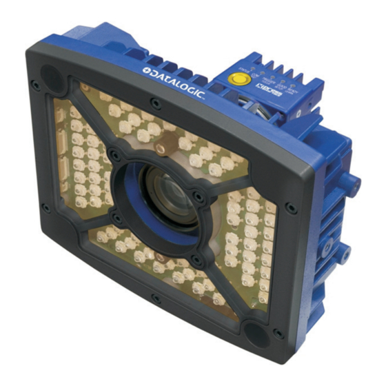
GENERAL VIEW Matrix 450™ + LT-03x Figure A Device Class Label Power LED Mounting Holes (6) Power - Serial Interfaces - I/O Connector Lens Cover MAC Address Label Lens Ethernet Connector (separate accessory) LT-03x Lighting System Ethernet Network Presence LED (separate accessory) HMI X-PRESS™... -
Page 13: Rapid Configuration
1 RAPID CONFIGURATION STEP 1 – ASSEMBLE THE READER The first step to perform is to assemble the accessories that make up the Matrix 450™ reader. The lens and lighting system or external illuminator must be used. This procedure shows an LT-03x series lighting system. -
Page 14: Required Accessories
Figure 2 – Assembling Matrix 450™ to LT-03x The mating bracket can be mounted in the reverse direction to create a compact version of the Matrix 450™ + LT-03x assembly. The compact assembly however will reduce access to the lens for the focusing procedure. -
Page 15: Step 2 - Connect The System
In the typical standalone layout shown in the figure below a serial host is connected to the Matrix 450™ + LT-03x. The reader operates in One Shot or Phase Mode and can use an external trigger to signal image acquisition. - Page 16 MATRIX 450™ REFERENCE MANUAL Alternatively, Matrix 450™ + LT-03x can be connected directly to an Ethernet host through the Gigabit Ethernet connection (CAB-GE0x). If an external trigger is not necessary, the layout is simplified. The LT-03x is powered directly from the PG-120 through the CAB-PG- 0105 cable.
- Page 17 RAPID CONFIGURATION CBX100/CBX500 Pinout for Matrix 450™ The table below gives the pinout of the CBX100/CBX500 terminal block connectors. Use this pinout when the Matrix 450™ reader is connected by means of the CBX100/CBX500: CBX100/500 Terminal Block Connectors Input Power...
-
Page 18: Step 3 - Mount And Position The Reader
MATRIX 450™ REFERENCE MANUAL STEP 3 – MOUNT AND POSITION THE READER To mount the Matrix 450™ + LT-03x assembly, use the L-shaped mounting bracket to obtain the most suitable position for the reader. The most common mounting configurations are shown in the figure below. Other mounting solutions are provided in Chapter 3 of this Reference Manual. -
Page 19: Step 4 - Focus The Reader
RAPID CONFIGURATION STEP 4 – FOCUS THE READER Matrix 450™ provides a built-in tool called Blue Diamonds™ to aid focusing the reader. The Blue Diamonds™ are accessed through the X-PRESS™ Interface. Remove the lens cover in order to focus the reader. -
Page 20: Step 5 - Calibrate Image Density
Replace the lens cover, screwing it tightly to the base. STEP 5 – CALIBRATE IMAGE DENSITY In order to function correctly to the fullest extent of its capabilities, Matrix 450™ must acquire information regarding image density or PPI (pixels per inch). This calibration takes place through the X-PRESS™... - Page 21 If the calibration cannot be reached after a timeout of about 5 (five) seconds Matrix 450™ will exit without saving the parameters to memory, the Setup LED will not remain on continuously but it will just stop blinking. In this case Matrix 450™ emits a long low pitched beep.
-
Page 22: Step 6 - X-Press™ Configuration
If the calibration cannot be reached after a timeout of about 5 (five) seconds Matrix 450™ will exit without saving the parameters to memory, the Setup LED will not remain on continuously but it will just stop blinking. In this case Matrix 450™ emits a long low pitched beep. -
Page 23: Reset Reader To Factory Default (Optional)
If the autolearning cannot be reached after a timeout of about 3 (three) minutes Matrix 450™ will exit without saving the parameters to memory, the Learn LED will not remain on continuously but it will just stop blinking. In this case Matrix 450™ emits a long low pitched beep. -
Page 24: Step 7 - Installing Visiset™ Configuration Program
MATRIX 450™ REFERENCE MANUAL STEP 7 – INSTALLING VISISET™ CONFIGURATION PROGRAM ™ VisiSet is a Datalogic reader configuration tool providing several important advantages: Setup Wizard for rapid configuration and new users; Defined configuration directly stored in the reader;... -
Page 25: Step 8 - Configuration Using Setup Wizard
RAPID CONFIGURATION STEP 8 – CONFIGURATION USING SETUP WIZARD The Setup Wizard option is advised for rapid configuration or for new users. It allows reader configuration in a few easy steps. Select the Setup Wizard button from the Main menu. Remove the lens cover and prepare the correct accessory lens for your application: Once the lens is fully tightened to the mechanical stop (Step 1), it can be rotated counterclockwise (up to one full turn without loosening the lens), so... - Page 26 MATRIX 450™ REFERENCE MANUAL Press the "Positioning" button. The reader continuously acquires images and gives visual feedback in the view image window. Move the Focusing Pattern to center it on the X-axis reference line at the center of the FOV and on the four delimiters (red points) in the acquired images which indicate the region in which the calibration algorithm is active.
- Page 27 RAPID CONFIGURATION Press the "Fine Focusing" button to activate the Fine Focusing Tool. The reader continuously acquires images and gives visual feedback on the focusing quality in the Focusing Tool window. In the Focusing Tool window, use the Zoom feature to make Fine Tuning easier.
- Page 28 Select a Code Setting Mode choice and press the "Code Setting" button. This step performs image density calibration in order for Matrix 450™ to function correctly and to the fullest extent of its capabilities. The Setup Result section of the Setup Wizard...
- Page 29 RAPID CONFIGURATION Substitute the Focusing and PPI Setup Chart with the application specific code, placing it in front of the reader at the same reading distance, then repeat step 6a and 6b. Setup Result Select a Saving Options choice and press the "Save"...
-
Page 30: Step 9 - Test Mode
MATRIX 450™ REFERENCE MANUAL STEP 9 – TEST MODE Use a code suitable to your application to test the reading performance of the system. Enter the Test function by pressing and holding the X-PRESS™ push button until the Test LED is on. -
Page 31: Advanced Reader Configuration
RAPID CONFIGURATION ADVANCED READER CONFIGURATION For further details on advanced product configuration, refer to this Reference Manual and the Matrix 450™ Help On Line on the installation Mini-DVD. The following are alternative or advanced reader configuration methods: Advanced Configuration Using VisiSet™... -
Page 32: Introduction
2 INTRODUCTION 2.1 PRODUCT DESCRIPTION Matrix 450™ is a 5.0 megapixels 2D Imager dedicated to middle range applications in the Transportation and Logistic industry. Matrix 450™ is an extremely powerful reader, capable to address ID applications never covered before by a 2D-Imager. - Page 33 INTRODUCTION Standard Application Program A Standard Application Program is factory-loaded onto Matrix 450™. This program controls code reading, data formatting, serial port and Ethernet interfacing, and many other operating and control parameters. It is completely user configurable from a Laptop or PC using the dedicated configuration software program VisiSet™, provided on Mini-DVD with the reader.
- Page 34 Industrial compact 2D reader Rugged full metal construction Sealed circular connectors IP65 protection class 50 °C max operating temperature Supply voltage ranges from 10 to 30 Vdc for Matrix 450™ (LT-03x requires 24 Vdc)
-
Page 35: Indicators And Keypad Button
INTRODUCTION 2.2 INDICATORS AND KEYPAD BUTTON Figure 17 - Indicators The following LED indicators are located on the reader: blue LED indicates that the reader is connected to the power supply (Figure 17, 1) POWER yellow LED indicates connection to the on-board Ethernet network (Figure 17, 2) In normal operating mode the colors and meaning of the five LEDs are illustrated in the following table: green LED indicates that the reader is ready to operate (Figure 17, 3) -
Page 36: Id-Net
MATRIX 450™ REFERENCE MANUAL 2.3 ID-NET™ The ID-NET™ network is a built-in high-speed interface dedicated for high-speed reader interconnection. ID-NET™ is in addition to the Main and Auxiliary serial interfaces. The following network configurations are available: ID-NET™ M/S Synchronized: Single station – multiple readers ID-NET™... -
Page 37: How To Setup/Configure The Reader Network
INTRODUCTION ID-NET™ M/S Multidata: Multiple stations – single reader ID-NET™ interface allows connection of readers reading objects placed on independent conveyors. All readers are typically located far away from each other and they use a dedicated presence sensor. At the end of each reading phase, each reader transmits its own data message to the host. Thanks to ID-NET™, data collection among readers is accomplished at a high speed without the need of an external multiplexing device. - Page 38 MATRIX 450™ REFERENCE MANUAL 5. Set Slave Address according desired value 1-31 from Reading System Layout > Device Network Setting > Slave Address parameter. Each reader must have a different Address on the ID-NET™ Network. 6. If necessary, set the ID-NET™ baudrate from the Reading System Layout >...
-
Page 39: Id-Net™ Slave Management Through Master
INTRODUCTION The reader network is ready. 2.3.2 ID-NET™ Slave Management Through Master When an ID-NET™ layout has already been configured, it is possible to modify the configuration of any Slave from VisiSet through the Master. This feature requires a minimum ID-NET™ Network Baud Rate of 38400. 1. - Page 40 MATRIX 450™ REFERENCE MANUAL If a wrong configuration is set or if the Slave Reading System Layout parameters are changed, the slave could lose the network connection. CAUTION...
-
Page 41: External Memory Backup And Restore Through Visiset
INTRODUCTION 2.4 EXTERNAL MEMORY BACKUP RESTORE THROUGH VISISET™ The "External Memory Backup" or "External Memory Restore" functions allow performing Complete Configuration and Environmental parameter storage for network and reading devices. Backup & Restore can be applied to any device connected to a Backup Module (BM100) or QL500 (Connection Module + Ethernet) or BM2x0 (Ethernet Module) regardless of the devices' network configuration. - Page 42 MATRIX 450™ REFERENCE MANUAL The VisiSet™ Main window shows information as the backup procedure is performed and a message indicating successful completion. Restore To perform a Restore: 1. Select "External Memory Restore" from the VisiSet™ Device menu 2. You will be warned that the current device configuration(s) will be overwritten. Confirm by...
- Page 43 INTRODUCTION The VisiSet™ Main window shows information as the restore procedure is performed and a message indicating successful completion. Replacement The External Memory Restore function also provides easy and secure Single Device Replacement: 1. Remove the device to be replaced. 2.
- Page 44 MATRIX 450™ REFERENCE MANUAL Erase To Erase any previous Backup: 1. Select "External Memory Erase" from the VisiSet™ Device menu 2. You will be warned that all device configurations in the current backup will be erased. Confirm by clicking Yes.
- Page 45 INTRODUCTION List To see a List of the current Backup: 1. Select "External Memory Read Backup" from the VisiSet™ Device menu. The VisiSet™ Main window shows a list of devices in the current Backup. The following is a list of possible error messages displayed on the VisiSet™ main window in case of an External Memory function failure: ...
-
Page 46: X-Press™ Human Machine Interface
MATRIX 450™ REFERENCE MANUAL 2.5 X-PRESS™ HUMAN MACHINE INTERFACE X-PRESS™ is the intuitive Human Machine Interface designed to improve ease of installation and maintenance. Status information is clearly presented by means of the five colored LEDs, whereas the single push button gives immediate access to the following relevant functions: ... - Page 47 INTRODUCTION Once button is pressed, the cycle of LEDs activation is as follows: yellow yellow green green STATUS TRIGGER GOOD READY FOCUS TEST SETUP LEARN Release Button to Exit yellow yellow green green STATUS TRIGGER GOOD READY TEST FOCUS SETUP LEARN Release Button to Enter Test Mode...
- Page 48 Setup LED will remain on continuously and Matrix 450™ emits 3 high pitched beeps. If the calibration cannot be reached after a timeout of about 5 (five) seconds Matrix 450™ will exit without saving the parameters to memory, the Setup LED will not remain on continuously...
-
Page 49: Model Description
Learn LED will remain on continuously and Matrix 450™ emits 3 high pitched beeps. If the calibration cannot be reached after a timeout of about 3 (three) minutes, Matrix 450™ will exit without saving the parameters to memory, the Learn LED will not remain on continuously but it will just stop blinking. -
Page 50: Accessories
MATRIX 450™ REFERENCE MANUAL 2.7 ACCESSORIES The following accessories can be used with the Matrix 450™ reader. Accessory Description Order No. Lenses LNS-1216 16 mm C-Mount Lens 5MP with anti-vibration components 93ACC0041 LNS-1225 25 mm C-Mount Lens 5MP with anti-vibration components... -
Page 51: Application Examples
INTRODUCTION Accessory Description Order No. Brackets BK-45-000 LT-03x L-shaped Mounting Bracket 93ACC0049 BK-45-010 Matrix 450™ Body Mounting Bracket 93ACC0050 BK-4990 Generic LT Bracket for LT-300 93ACC1805 Software Management Datalogic WebSentinel- Supervisor (manages up to 5 arrays) 93A100027 Images-005 Datalogic WebSentinel-... -
Page 52: Loading/Unloading
2.8.2 Loading/Unloading Matrix 450™ can be applied in an over-the-belt style for unattended scanning in motion and also in a semi-automated style, performed in presentation mode to the overhead reader during the manual item handling. -
Page 53: Automated Postal Sorting
Matrix 450™ can also be applied in scanning applications of large conveyors or multi-sided reading. Through the ID-NET clustering, multiple readers can be effectively combined to extend the scanning area. -
Page 54: Order Fulfilment
Matrix 450™ is a valid solution for scanning large stationary objects, from pallets to stacked trays. There are multiple advantages in using Matrix 450™. First of all, no parts in movement – no scan rotor and no oscillating mirror – delivers crucial advantages in terms of maximum tolerance to vibration and shock, as for example a forklift may generate. -
Page 55: Manual Presentation Scanning
The complete set of integrated functionalities makes Matrix 450™ a comprehensive solution for manual scanning, easy to deploy, easy to use and with minimum cost for maintenance. -
Page 56: Installation
MATRIX 450™ REFERENCE MANUAL 3 INSTALLATION 3.1 PACKAGE CONTENTS Verify that the Matrix 450™ reader and all the parts supplied with the equipment are present and intact when opening the packaging; the list of parts includes: Matrix 450™ reader with Lens Cover ... -
Page 57: Mechanical Dimensions
3.2 MECHANICAL DIMENSIONS [3.86] 72.5 [2.85] Matrix 450™ is designed to be used with one of the LT-03x Series Lighting Systems. In this configuration the L-shaped LT-03x mounting bracket must be used to support the whole assembly, (refer to Figure 20). - Page 58 MATRIX 450™ REFERENCE MANUAL [7.95] 22.5 [0.89] [0.35] [1.77] [2.17] [0.20] [4.92] [5.61] M 5 x 8 n°3 compact assembly [7.05] [7.95] [0.20] [5.91] [3.54] standard assembly [1.18] Figure 20 – Matrix 450™ + LT-03x + L-Bracket Overall Dimensions...
-
Page 59: Mounting And Positioning Matrix 450
Using the LT-03x L-shaped mounting bracket you can obtain rotation on the various axes of the reader as shown in the diagrams below: Figure 21 –Mounting LT-03x Bracket Tilt Pitch Pitch Tilt Figure 22 – Matrix 450™ Positioning with LT-03x Bracket... - Page 60 Pitch Figure 23 – Matrix 450™ Positioning with Two LT-03x Brackets In applications where the LT-03x Series Lighting Systems are not used, Matrix 450™ can be mounted using the body mounting bracket accessory shown in the diagrams below; and you can obtain rotation on the various axes of the reader.
- Page 61 Assure at least 10° Minimize Figure 25 - Pitch angle Figure 26 - Skew angle The Tilt angle is represented by the value T in Figure 27. Matrix 450™ can read labels with any tilt angle. Minimize Figure 27 - Tilt angle...
-
Page 62: Cbx Electrical Connections
CAB-MSxx accessory cables. These accessory cables terminate in a 19-pin connector on the Matrix 450™ side and in a 25-pin male D-sub connector on the CBX side. We recommend making system connections through one of the CBX connection boxes since they offer the advantages of easy connection, easy device replacement and filtered reference signals. -
Page 63: Power Supply
Accessory Power Supplies Power Supply Number of Matrix 450™+LT-03xs Supported PG-120 PWR-120 PWR-240 PWR-480A If using separate power sources for LT-03x and Matrix 450™, make sure that LT-03x is powered up before Matrix 450™ in order to be correctly recognized. NOTE... -
Page 64: Main Serial Interface
MATRIX 450™ REFERENCE MANUAL 4.2 MAIN SERIAL INTERFACE Do not connect to the Main Interface spring clamp terminals if using Host Interface Modules (Fieldbus) with the CBX500. CAUTION The signals relative to the following serial interface types are available on the CBX spring clamp terminal blocks. -
Page 65: Rs485 Full-Duplex Interface
IDLE Figure 30 - RS232 Control Signals If the RTS/CTS handshaking protocol is enabled, the Matrix 450™ activates the RTS output to indicate a message is to be transmitted. The receiving unit activates the CTS input to enable the transmission. -
Page 66: Rs485 Half-Duplex Interface
The RS485 half-duplex (3 wires + shield) interface is used for polled communication protocols. It can be used for Multidrop connections with a Datalogic Multiplexer, exploiting a proprietary protocol based on polled mode called MUX32 protocol, where a master device polls slave devices to collect data. - Page 67 In a Multiplexer layout, the Multidrop address must also be set via serial channel by the VisiSet™ utility or by the Host Programming Mode. Figure 34 shows a multidrop configuration with Matrix 450™ readers connected to a Multiplexer. This is an example of multidrop wiring. Consult the multiplexer manual for complete wiring instructions.
- Page 68 Termination Resistor. Power Unit Earth Figure 34 - Matrix 450™ Multidrop Connection to a Multiplexer * When using CBX500, the Main interface multidrop network signals: Shield, SGND, RTX+and RTX- are repeated on terminal connector row 4 to facilitate system cabling.
-
Page 69: Id-Net™ Interface
1200 m 900 m 700 m * Application dependent, contact your Datalogic Automation representative for details. The default ID-NET™ baudrate is 500 kbps. Lower ID-NET™ baudrates allow longer cable lengths. The baudrate is software configurable by authorized Datalogic Automation personnel only. -
Page 70: Id-Net™ Response Time
MATRIX 450™ REFERENCE MANUAL 4.3.2 ID-NET™ Response Time The following figure shows the response time of the ID-NET™ network. This time is defined as the period between the Trigger activation and the beginning of data transmission to the Host. Max ID-NET™ Response Time... - Page 71 CBX ELECTRICAL CONNECTIONS CBX100/500 Main Interface HOST Reader RS232/RS485 Master Shield Shield Earth ID-NET™ Termination Resistor. Power Unit Earth CBX100/500 Shield (blue) Reader (white) (black) Slave Shield Shield floating ID-NET™ Termination Resistor. Power Unit Earth CBX100/500 Shield (blue) Reader (white) (black) Slave (up to 31)
- Page 72 MATRIX 450™ REFERENCE MANUAL CBX100/500 CBX100/500 Main Interface HOST Reader RS232/RS485 Master Shield Shield Earth ID-NET™ Termination Resistor. Earth CBX100/500 CBX100/500 Shield (blue) Reader (white) Slave Shield Shield floating ID-NET™ Termination Resistor. Earth CBX100/500 CBX100/500 Shield (blue) Reader (white) Slave...
- Page 73 CBX ELECTRICAL CONNECTIONS CBX100/500 CBX100/500 Main Interface HOST Reader RS232/RS485 Master Shield Shield Earth ID-NET™ Termination Resistor. Earth CBX100/500 CBX100/500 Shield (blue) Reader (white) Slave Shield Shield floating ID-NET™ Termination Resistor. Earth CBX100/500 CBX100/500 Shield (blue) Reader (white) Slave (up to 31) Shield floating ID-NET™...
-
Page 74: Id-Net™ Network Termination
MATRIX 450™ REFERENCE MANUAL 4.3.3 ID-NET™ Network Termination The network must be properly terminated in the first and last reader of the network. This is done by setting the ID-NET™ Termination Resistance Switch in the CBX100/500 to ON. 4.4 AUXILIARY RS232 INTERFACE The RS232 auxiliary interface is available for Point-to-Point, Pass Through or Master/Slave connections. -
Page 75: Inputs
CBX ELECTRICAL CONNECTIONS 4.5 INPUTS There are two optocoupled polarity insensitive inputs available on the reader: Input 1 (External Trigger) and Input 2, a generic input: The External Trigger can be used in One Shot Mode or in Phase Mode. Its main functions are: ... - Page 76 MATRIX 450™ REFERENCE MANUAL EXTERNAL TRIGGER INPUT CONNECTIONS USING CBX POWER Power is available directly to the Input Device, independently from the Power Supply Switch inside the CBX. CAUTION PH-1 Photocell (PNP) (brown) (black) (blue) Figure 41 – PH-1 External Trigger Using CBX Power...
- Page 77 CBX ELECTRICAL CONNECTIONS CBX100/500 Function Power Source - Inputs Input 2 A (polarity insensitive) Input 2 B (polarity insensitive) Power Reference - Inputs INPUT 2 CONNECTIONS USING CBX POWER Power is available directly to the Input Device, independently from the Power Supply Switch inside the CBX.
-
Page 78: Outputs
MATRIX 450™ REFERENCE MANUAL Input Device Pulled up to External Input Device Power Input Signal Figure 46 - NPN Input 2 Using External Power 4.6 OUTPUTS Two optocoupled general purpose outputs are available. The meaning of the two outputs Output 1 and Output 2 can be defined by the user. They are typically used either to signal the data collection result or to control an external lighting system. - Page 79 CBX ELECTRICAL CONNECTIONS OUTPUT CONNECTIONS USING CBX POWER Power is available directly to the Output Device, independently from the Power Supply Switch inside the CBX. CAUTION Output Device Power to Output Output device Signal Output device Reference Figure 47 - Open Emitter Output Using CBX Power Output Device Power to Output device...
-
Page 80: External Illuminators
Control Signal + The LT-300 Ring Lighting System is designed for reading codes produced by Dot Peening or Laser Etching on flat, reflective parts. Applications using this illuminator with Matrix 450™ could require alternative mounting solutions to be provided by the customer. -
Page 81: User Interface - Host
CBX ELECTRICAL CONNECTIONS 4.8 USER INTERFACE - HOST The following table contains the pinout for standard RS232 PC Host interface. For other user interface types please refer to their own manual. RS232 PC-side connections 9-pin male connector 25-pin male connector Name Name... -
Page 82: Matrix 450™ Electrical Connections
5 MATRIX 450™ ELECTRICAL CONNECTIONS 5.1 MATRIX 450™ POWER, SERIAL HOST, I/O CONNECTOR The Matrix 450™ reader is equipped with an M16 19-pin male connector (Binder, 423 Series) for connection to the power supply, serial interfaces and input/output signals. The details of the connector pins are indicated in the following table. -
Page 83: Matrix 450™ Lighting System Control Connector
5.2 MATRIX 450™ LIGHTING SYSTEM CONTROL CONNECTOR Matrix 450™ controls the LT-03x series lighting system from this connector through software. Matrix 450™ can also receive power from this input, normally from the LT-03x lighting system through the CAB-LD-002 cable. Matrix 450™ cannot source power through this connector. -
Page 84: Matrix 450™ Gigaethernet Connector (**)
V+ (10 - 30 Vdc) V- (Ground) SHIELD CHASSIS Chassis Earth Ground Earth Ground Figure 57 - Power Supply Connection The allowed supply voltage range for Matrix 450™ is 10 to 30 Vdc, however the LT-03x Lighting System requires 24 Vdc. -
Page 85: Recommended Power Supplies
PWR-120 PWR-240 PWR-480A If using separate power sources for LT-03x and Matrix 450™, make sure that LT-03x is powered up before Matrix 450™ in order to be correctly recognized. NOTE 5.5 MAIN SERIAL INTERFACE The signals relative to the following serial interface types are available on the M16 19-pin connector: The main serial interface type and its parameters (baud rate, data bits, etc.) can be... -
Page 86: Rs485 Full-Duplex Interface
The RTS and CTS signals control data transmission and synchronize the connected devices. Figure 59 - RS232 Control Signals If the RTS/CTS handshaking protocol is enabled, Matrix 450™ activates the RTS output to indicate a message is to be transmitted. The receiving unit activates the CTS input to enable the transmission. - Page 87 MATRIX 450™ ELECTRICAL CONNECTIONS MATRIX USER INTERFACE RX485 TX485 Reference Ground SHIELD Chassis Earth Ground Earth Ground Figure 60 - RS485 Full-duplex Connections For applications that do not use RX485 signals, do not leave these lines floating but connect them to GND as shown below.
-
Page 88: Rs485 Half-Duplex Interface
The RS485 half-duplex (3 wires + shield) interface is available for polled communication protocols. It can be used for Multidrop connections with a Datalogic Multiplexer, exploiting a proprietary protocol based on polled mode called MUX32 protocol, where a master device polls slave devices to collect data. - Page 89 MATRIX 450™ ELECTRICAL CONNECTIONS The figure below shows a multidrop configuration with Matrix 450™ readers connected to a Multiplexer. This is an example of multidrop wiring. Consult the multiplexer manual for complete wiring instructions. CAUTION Max 2 m 120 Ohm...
-
Page 90: Id-Net™ Interface
1200 m 900 m 700 m * Application dependent, contact your Datalogic Automation representative for details. The default ID-NET™ baudrate is 500 kbps. Lower ID-NET™ baudrates allow longer cable lengths. The baudrate is software configurable by authorized Datalogic Automation personnel only. -
Page 91: Id-Net™ Response Time
MATRIX 450™ ELECTRICAL CONNECTIONS 5.6.2 ID-NET™ Response Time The following figure shows the response time of the ID-NET™ network. This time is defined as the period between the Trigger activation and the beginning of data transmission to the Host. Max ID-NET™ Response Time... - Page 92 MATRIX 450™ REFERENCE MANUAL Max 0.3 m 120 Ohm Reader Slave (up to 31) Power Unit Reader Slave Power Unit Reader Master 120 Ohm Cable Shield Power Unit RS232/RS485 HOST Figure 65 – ID-NET™ Network Connections with Isolated Power Units...
- Page 93 MATRIX 450™ ELECTRICAL CONNECTIONS Max 0.3 m 120 Ohm Reader Slave (up to 31) Reader Slave Reader Master 120 Ohm Vdc GND Cable Shield POWER RS232/RS485 HOST Figure 66 - ID-NET™ Network Connections with Common Power Branch Network...
- Page 94 MATRIX 450™ REFERENCE MANUAL Max 0.3 m 120 Ohm Reader Slave (up to 31) Reader Slave Reader Master 120 Ohm Vdc GND Cable Shield POWER RS232/RS485 HOST Figure 67 – ID-NET™ Network Connections with Common Power Star Network...
-
Page 95: Id-Net™ Network Termination
MATRIX 450™ ELECTRICAL CONNECTIONS 5.6.3 ID-NET™ Network Termination The network must be properly terminated by a 120 Ohm resistor at the first and last reader of the network. 5.7 AUXILIARY RS232 INTERFACE The RS232 auxiliary interface is available for Point-to-Point, Pass Through or Master/Slave connections. -
Page 96: Ethernet Interface
LAN or directly to a host PC. There is no need to use a crossover adapter since Matrix 450™ incorporates an auto-cross function. The following is an example of a connection to a LAN using a CAB-GE0x straight through... -
Page 97: Inputs
MATRIX 450™ ELECTRICAL CONNECTIONS 5.9 INPUTS There are two optocoupled polarity insensitive inputs available on the M16 19-pin connector of the reader: Input 1 (External Trigger) and Input 2, a generic input: The External Trigger can be used in One Shot Mode or in Phase Mode. Its main functions are: ... - Page 98 EXTERNAL TRIGGER INPUT CONNECTIONS USING MATRIX 450™ POWER Matrix 410™ EXTERNAL TRIGGER Signal Ground Figure 71 – External Trigger PNP Using Matrix 450™ Power Matrix 410™ EXTERNAL TRIGGER Signal Ground Figure 72 - External Trigger NPN Using Matrix 450™ Power EXTERNAL TRIGGER INPUT CONNECTIONS USING EXTERNAL POWER Vext 30 Vdc max.
- Page 99 Power Supply input voltage - INPUT 2 CONNECTIONS USING MATRIX 450™ POWER Matrix 410™ INPUT DEVICE Signal Ground Figure 75 - Input PNP Using Matrix 450™ Power Matrix 410™ INPUT DEVICE Signal Ground Figure 76 - Input NPN Using Matrix 450™ Power...
-
Page 100: Outputs
MATRIX 450™ REFERENCE MANUAL INPUT 2 CONNECTIONS USING EXTERNAL POWER Vext 30 Vdc max. I NPUT DEVICE Matrix 410™ Signal Figure 77 - Input PNP Using External Power Vext 30 Vdc max. Matrix 410™ I NPUT DEVICE Signal Figure 78 - Input NPN Using External Power 5.10 OUTPUTS... - Page 101 MATRIX 450™ ELECTRICAL CONNECTIONS The output signals are fully programmable being determined by the configured Activation/Deactivation events, Deactivation Timeout or a combination of the two. Refer to the Digital I/O folder in the VisiSet™ Help On Line for further details.
-
Page 102: User Interface
The following wiring diagram shows a simple test cable including power, external (push- button) trigger and PC RS232 COM port connections. M16 19-pin female 9-pin D-sub female Matrix 450™ B I1A Power Supply Power GND VS (10 – 30 VDC) Trigger Figure 81- Test Cable for Matrix 450™... -
Page 103: Typical Layouts
Dotted lines in the figures refer to optional hardware configurations within the particular layout. If using separate power sources for LT-03x and Matrix 450™, make sure that LT-03x is powered up before Matrix 450™ in order to be correctly recognized. NOTE 6.1 POINT-TO-POINT... -
Page 104: Embedded (On-Board) Gigaethernet
Folder in the VisiSet™ Help On Line. In a Point-to-Point layout the reader is connected to a local host by using a CAB-GE0x cable. There is no need to use a crossover adapter since Matrix 450™ incorporates an autocross function. -
Page 105: Tcp/Ip Ethernet (Bm2X0)
TYPICAL LAYOUTS 6.1.3 TCP/IP Ethernet (BM2x0) In this layout the data is transmitted to the Host on the TCP/IP Ethernet interface (CBX500 with BM2x0 Host Interface Module installed). The RS232 auxiliary interface can be used for reader configuration by connecting a laptop computer running VisiSet™. Host Mode programming can be accomplished either through the TCP/IP Ethernet interface or the Auxiliary interface. -
Page 106: Fieldbus
MATRIX 450™ REFERENCE MANUAL 6.1.4 Fieldbus In this layout a single reader functions as a Slave node on a Fieldbus network. The data is transmitted to the Host through an accessory Fieldbus interface board installed inside the CBX500 connection box. -
Page 107: Ethernet Networks
6.2 ETHERNET NETWORKS 6.2.1 External Trigger Ethernet Host When using a Local Area Network (LAN), one or more Matrix 450™ readers can be connected to the network by using CAB-GE0x cables. In the example below an External Trigger is used which is connected through a CBX connection box. -
Page 108: No Trigger Ethernet Host
MATRIX 450™ REFERENCE MANUAL 6.2.2 No Trigger Ethernet Host The LAN connections are simplified when one or more Matrix 450™ readers work in Continuous reading mode or when the Trigger is supplied by the host. In this case the CBX connection boxes are not necessary. -
Page 109: Pass-Through Networks
TYPICAL LAYOUTS 6.3 PASS-THROUGH NETWORKS 6.3.1 Pass-Through on RS232 Pass-through mode allows two or more devices to be connected to a single external serial interface. Each reader transmits the messages received by the Auxiliary interface onto the Main interface. All messages will be passed through this chain to the host. When One Shot or Phase Mode operating mode is used, the reader can be activated by an External Trigger (for example a pulse from a photoelectric sensor) when the object enters its reading zone. -
Page 110: Pass-Through On Id-Net
(Master and Slaves) to accept input on the Auxiliary interface, for example to connect a device such as a hand-held reader for manual code reading capability. Each Matrix 450™ transmits its own messages plus any messages received by its Auxiliary interface onto the ID-NET™ interface. The Master passes all messages to the Host. -
Page 111: Id-Net™ Networks
TYPICAL LAYOUTS 6.4 ID-NET™ NETWORKS 6.4.1 M/S Synchronized Serial Host The ID-NET™ connection is used to collect data from several readers to build a multi-point or a multi-sided reading system; there can be one master and up to 31 slaves connected together. - Page 112 BA600 ID-NET™ Out BA400 Ext. Power BA500 Trigger BA300 Service Figure 91 - ID-NET™ Synchronized Layout Matrix 450™ Master with CBX500 + Matrix 450™ Slaves with QL150 Power CAB-AUX03 CAB-AUX03 QL150 QL150 ID-NET™ CBL-1480-xx CBL-1480-xx QL300...
-
Page 113: M/S Synchronized Tcp/Ip Host
TYPICAL LAYOUTS 6.4.2 M/S Synchronized TCP/IP Host The same configuration can be made to a Host using a TCP/IP Ethernet interface. In this case the Master is connected to a CBX500 having the BM2x0 Host Interface Module installed. It could also be connected to the QL500 and in both cases the External Memory Backup and Restore features are available. -
Page 114: M/S Multidata Serial Host
MATRIX 450™ REFERENCE MANUAL 6.4.3 M/S Multidata Serial Host For a Master/Slave Multidata layout each reader has its own reading phase independent from the others; each single message is sent from the master reader to the Host computer. Host Master... -
Page 115: M/S Multidata Tcp/Ip Host
TYPICAL LAYOUTS 6.4.4 M/S Multidata TCP/IP Host The same configuration can be made to a Host using a TCP/IP Ethernet interface. In this case the Master is connected to a CBX500 with BM2x0 Host Interface Module installed. It could also be connected to the QL500 and in both cases the External Memory Backup and Restore features are available. -
Page 116: M/S Synchronized And Multidata Fieldbus Host
MATRIX 450™ REFERENCE MANUAL 6.4.5 M/S Synchronized and Multidata Fieldbus Host Alternatively, the Master reader can communicate to the Host as a Slave node on a Fieldbus network. This requires using an accessory Fieldbus interface board installed inside the CBX500 connection box. -
Page 117: Reading Features
Figure 98 – Reading Distance References Example: The FOV for a Matrix 450 800-030 base using the 16 mm lens at a focus distance of 1000 mm is: = 2 [(1000 mm + 44 mm) tan (28.8°/2)] = 536 mm = 2 [(1000 mm + 44 mm) tan (24.5°/2)] = 453 mm... -
Page 118: Reading Diagrams
Data Matrix ECC 200 (2D code) from the Test Charts provided with the reader. Testing should be performed with the actual Matrix 450™ + LT-03x assembly using application codes in order to evaluate whether maximizing application performance requires adjustments to the HW/SW configuration with respect to the Reference Conditions given under each diagram. - Page 119 READING FEATURES Matrix 450™ + LNS-1216 Code 1D 0.38 mm (15 mils) Code 1D 0.50 mm (20 mils) (cm) 140 150 (in) Reading Distance CONDITIONS: Hardware Settings Code Symbology Code 128 Code Resolution 0.38 mm (15 mils) 0.50 mm (20 mils)
- Page 120 MATRIX 450™ REFERENCE MANUAL Matrix 450™ + LNS-1225 Code 1D 0.20 mm (8 mils) (cm) (in) Reading Distance CONDITIONS: Hardware Settings Code Symbology Code 128 Code Resolution 0.20 mm (8 mils) Focal Length 25 mm Aperture Stop F/5.6 Focus Distance 1.000 mm (39.4 inches)
- Page 121 READING FEATURES Matrix 450™ + LNS-1225 Code 1D 0.33 mm (13 mils) Code 1D 0.38 mm (15 mils) (cm) 175 180 210 215 (in) Reading Distance CONDITIONS: Hardware Settings Code Symbology Code 128 Code Resolution 0.33 mm (13 mils) 0.38 mm (15 mils)
- Page 122 MATRIX 450™ REFERENCE MANUAL Matrix 450™ + LNS-1225 Code 1D 0.30 mm (12 mils) Code 2D 0.61 mm (24 mils) (cm) 160 165 (in) Reading Distance CONDITIONS: Hardware Settings Code Symbology Code 128 Data Matrix ECC 200 Code Resolution 0.30 mm (12 mils) 0.61 mm (24 mils)
- Page 123 READING FEATURES Matrix 450™ + LNS-1225 Code 1D 0.51 mm (20 mils) (cm) 250 260 (in) 108 112 116 120 Reading Distance CONDITIONS: Hardware Settings Code Symbology Code 128 Code Resolution 0.51 mm (20 mils) Focal Length 25 mm Aperture Stop F/5.6...
- Page 124 MATRIX 450™ REFERENCE MANUAL Matrix 450™ + LNS-1235 Code 1D 0.20 mm (8 mils) (cm) (in) Reading Distance CONDITIONS: Hardware Settings Code Symbology Code 128 Code Resolution 0.20 mm (8 mils) Focal Length 35 mm Aperture Stop F/11 Focus Distance 1.450 mm (57.1 inches)
- Page 125 READING FEATURES Matrix 450™ + LNS-1235 Code 1D 0.25 mm (10 mils) Code 1D 0.30 mm (12 mils) (cm) (in) Reading Distance CONDITIONS: Hardware Settings Code Symbology Code 128 Code Resolution 0.25 mm (10 mils) 0.30 mm (12 mils) Focal Length...
- Page 126 MATRIX 450™ REFERENCE MANUAL Matrix 450™ + LNS-1235 Code 2D 0.51 mm (20 mils) Code 2D 0.61 mm (24 mils) (cm) (in) Reading Distance CONDITIONS: Hardware Settings Code Symbology Data Matrix ECC 200 Code Resolution 0.51 mm (20 mils) 0.61 mm (24 mils)
- Page 127 READING FEATURES Matrix 450™ + LNS-1250 Code 1D 0.15 mm (6 mils) (cm) (in) Reading Distance CONDITIONS: Hardware Settings Code Symbology Code 128 Code Resolution 0.15 mm (6 mils) Focal Length 50 mm Aperture Stop Focus Distance 1.600 mm (57.1 inches) Tilt Angle 45°...
-
Page 128: Maximum Line Speed And Exposure Time Calculations
MATRIX 450™ REFERENCE MANUAL 7.3 MAXIMUM LINE SPEED AND EXPOSURE TIME CALCULATIONS The Exposure Time (or Shutter) parameter defines the time during which the image will be exposed to the reader sensor to be acquired. This parameter depends heavily on the environmental conditions (external lighting system, image contrast etc.). - Page 129 READING FEATURES and LS are represented in the graph below as the curved line for X (code exp (max) (max) resolution). Values above the curve result in blurring. In practice, the application values are somewhere below the theoretical line, (in the green area), due to environmental and other conditions.
-
Page 130: Software Configuration
MATRIX 450™ REFERENCE MANUAL 8 SOFTWARE CONFIGURATION Software configuration of your Matrix 450™ for static reading or simple code reading applications can be accomplished by the Rapid Configuration procedure using the X- PRESS™ HMI (which requires no external configuration program) or by using the VisiSet™... -
Page 131: Installing Visiset
After completing the mechanical and electrical connections to Matrix 450™, you can begin software configuration as follows: 1. Power on the Matrix 450™ reader. Wait for the reader startup. The system bootstrap requires a few seconds to be completed. The reader automatically enters Run Mode. -
Page 132: Visiset™ Options
MATRIX 450™ REFERENCE MANUAL 8.3.1 VisiSet™ Options The Options item from the VisiSet™ menu (see Figure 99) presents a window allowing you to configure: the logging function (Log) VisiSet™ window properties (Environment) VisiSet™ communication channel (Communication) Figure 100 - Options - Log... - Page 133 SOFTWARE CONFIGURATION Figure 102 - Options – Communication: Serial Port Figure 103 - Options – Communication: Ethernet...
-
Page 134: Configuration
MATRIX 450™ REFERENCE MANUAL 8.4 CONFIGURATION Once connected to Matrix 450™ as described in par. 8.3, you can modify the configuration parameters as follows: 1. Press the Calibration Tool button from the Main Menu. Matrix 450™ will download its permanent memory configuration parameters with the default values (if it is the first time) to VisiSet™. -
Page 135: Edit Reader Parameters
SOFTWARE CONFIGURATION 8.4.1 Edit Reader Parameters The Parameter Setup window displays the configuration parameters grouped in a series of folders. Each parameter can be modified by selecting a different item from the prescribed list in the box, or by typing new values directly into the parameter box. By right clicking the mouse when positioned over the name of a specific Parameter or Group, a pop-up menu appears allowing you to directly manage that particular parameter or group. - Page 136 Allows configuring the device according to the desired layout: Standalone, ID-NET™ or Master/Slave RS232 WebSentinel Enables the Ethernet WebSentinel Agent for communication with the Datalogic WebSentinel™ plant array monitor. Ethernet Sets the parameters related to the on board Ethernet interface and to its communication channels.
-
Page 137: Send Configuration Options
SOFTWARE CONFIGURATION When all the configuration parameters are set correctly, save them to the Matrix 450™ reader by pressing the Send button. See Figure 104. For successive configuration of other readers or for backup/archive copies, it is possible to save the configuration onto your PC by selecting the Save Configuration File option from the File menu. - Page 138 MATRIX 450™ REFERENCE MANUAL Environmental Parameters regard the device Identity and Position in a Network (ID-NET™, Master/Slave, Ethernet) and are not influenced by the "Send Default Configuration" and "Send Configuration" commands. This allows individual devices to be configured differently without affecting their recognized position in the network.
- Page 139 SOFTWARE CONFIGURATION PROFIBUS - Node Address DEVICENET - Node Address ETHERNET-IP - IP Addressing Mode - IP Address - Subnet Mask - Gateway Address PROFINET IO - IP Addressing Mode - IP Address - Subnet Mask - Gateway Address CANOPEN - Node Address CC-LINK - Node Address...
- Page 140 MATRIX 450™ REFERENCE MANUAL For device replacement it is necessary to send the previously saved configuration (both Configuration and Environmental parameters) to the new device. To do this select "Send Configuration with Options" from the Device Menu and check the Environmental Parameters...
-
Page 141: Calibration
Parameter Setup window: Figure 105 - Calibration OK This tool provides a "real-time" image display while Matrix 450™ is reading. It also gives immediate results on the performance of the installed Matrix 450™ reader. If Self Tuning is enabled, the Calibration Tool window indicates the region where the calibration algorithm is performed: it is within the central box delimited by four red dots. - Page 142 MATRIX 450™ REFERENCE MANUAL If you want to save the temporary configuration to permanent memory, you must first close the Calibration Tool window. Then, you must disable the Interactive Mode and select the Permanent Memory option from the Send Configuration item in the Device menu.
- Page 143 SOFTWARE CONFIGURATION Over-exposure: To correct this result it is recommended to change the following parameters in their order of appearance: 1. decrease the Gain 2. decrease the Exposure Time Figure 107 - Example Over Exposure: Too Light...
- Page 144 MATRIX 450™ REFERENCE MANUAL Moving code out of the Field of View: To correct this result and have the code completely visible in F.O.V., it is possible to follow one or both the procedures listed below: reposition the reader ...
-
Page 145: Multi Image Acquisition Settings
From Readable Not Readable For more details see the Matrix 450™ Help On-Line. Self Tuning Image Processing In the Image Processing parameter setup menu, the Self Tuning parameters manage the Image Processing and Symbology related parameters. They perform different processing... -
Page 146: Region Of Interest Windowing
The Top, Bottom, Left and Right parameters allow to precisely define the image window to be processed, visualized and saved. In Matrix 450™ the frame rate is dependent on the number of lines (or rows) in the defined window. The smaller the window, the lower the frame period, and consequently the higher the frame rate. -
Page 147: Image Capture And Decoding
SOFTWARE CONFIGURATION 8.5 IMAGE CAPTURE AND DECODING By using the Capture Image and Decode Last Image functions from the VisiSet™ Main menu, you can get information about the image decodable codes in terms of Symbology, encoded Data, Position and Orientation, Decode Time and Code Quality Assessment Metrics. Figure 109 - Capture and Decoding Functions 8.6 STATISTICS Statistics on the reading performance can be viewed by enabling the Statistics parameter... -
Page 148: Maintenance
MATRIX 450™ REFERENCE MANUAL 9 MAINTENANCE 9.1 CLEANING Clean the reading window (see Figure A, 1) periodically for continued correct operation of the reader. Dust, dirt, etc. on the window may alter the reading performance. Repeat the operation frequently in particularly dirty environments. -
Page 149: Troubleshooting
F1 key, or select Help>Paramters Help from the command menu. If you’re unable to fix the problem and you’re going to contact your local Datalogic office or Datalogic Partner or ARC, we suggest providing (if possible): Application Program version, Parameter Configuration file, Serial Number and Order Number of your reader. - Page 150 MATRIX 450™ REFERENCE MANUAL TROUBLESHOOTING GUIDE Problem Suggestion One Shot or Phase Mode In the Operating Mode folder check the settings for using serial trigger source: Reading Phase-ON, Acquisition Trigger the ”TRIGGER” LED is not Reading Phase-OFF parameters. blinking.
- Page 151 TROUBLESHOOTING TROUBLESHOOTING GUIDE Problem Suggestion Communication: Are the host serial port settings the same as the reader data transferred to the host serial port settings? are incorrect, corrupted or In VisiSet Communication folder check the settings of incomplete. Header and Terminator String parameters.
-
Page 152: Technical Features
11 TECHNICAL FEATURES ELECTRICAL FEATURES Power Supply Voltage 24 Vdc ± 20% Consumption (max) 2.5 A ( 0.5 A Matrix 450™; 2 A LT-03x ) Communication Interfaces Main - RS232 2400 to 115200 bit/s - RS485 full-duplex 2400 to 115200 bit/s... - Page 153 Dimensions 123 x 64 x 143 mm (4.8 x 2.5 x 5.6 in) Matrix 450™ Matrix 450™ + LT-03x 202 x 213 x 179 mm (8.0 x 8.4 x 7.1 in) Weight (with lens and LT-03x) 3000 g. (6.6 lbs.)
-
Page 154: Glossary
GLOSSARY (Association for Automatic Identification and Mobility): AIM Global is the international trade association representing automatic identification and mobility technology solution providers. AIM DPM Quality Guideline Standard applicable to the symbol quality assessment of direct part marking (DPM) performed in using two-dimensional bar code symbols. It defines modifications to the measurement and grading of several symbol quality parameters. - Page 155 Depth of Field The difference between the minimum and the maximum distance of the object in the field of view that appears to be in focus. Diffused Illumination Distributed soft lighting from a wide variety of angles used to eliminate shadows and direct reflection effects from highly reflective surfaces.
- Page 156 (International Organization for Standardization): A network of the national standards institutes of several countries producing world-wide industrial and commercial standards. LED (Light Emitting Diode) A low power electronic light source commonly used as an indicator light. It uses less power than an incandescent light bulb but more than a Liquid Crystal Display (LCD).
-
Page 157: Index
Main Serial Interface, 52, 73 Application Examples, 39 Maintenance, 136 Auxiliary RS232 Interface, 62, 83 Mechanical Dimensions, 45 Model Description, 37 Mounting and Positioning Matrix 450™, 47 Calibration, 129 CBX Electrical Connections, 50 Compliance, vii Optical Accessory Selection, 105 Connectors... - Page 158 40050 Monte San Pietro Bologna - Italy www.automation.datalogic.com declares that the MATRIX 450; 2D Imager and all its models are in conformity with the requirements of the European Council Directives listed below: 2004 / 108 / EC EMC Directive ______________________________________________...
- Page 159 EC-032 DECLARATION OF CONFORMITY Rev.: 4 Pag.: 1 di 1 Datalogic Automation S.r.l. Via Lavino 265 40050 Monte San Pietro Bologna - Italy www.automation.datalogic.com declares that the LT-series; Lighting System and all its models are in conformity with the requirements of the European Council Directives listed below:...
- Page 160 www.automation.datalogic.com...