Advertisement
Quick Links
Advertisement

Related Manuals for YOKOGAWA 701989


Summary of Contents for YOKOGAWA 701989
- Page 1 User’s Manual Model 701989 PBL250 Logic Probe IM 701989-01E 5th Edition...
- Page 2 User’s Manual precautions, and other important information about the PBL250 Logic Probe. The “E” in the manual number is the language code. Contact information of Yokogawa offices worldwide is provided on the following sheet. Document No. Description PIM 113-01Z2...
- Page 3 Note Calls attention to information that is important for proper operation of the instrument. IM 701989-01E...
-
Page 4: Checking The Contents Of The Package
B9852VX Microclips (red, set of 8) B9852VY (with number labels) 10 Number labels 11 Stacking spacer − 12 Manuals IM 701989-01E This manual IM 701988-92 Document for China IM 701988-93Z2 Document for Korea PIM 113-01Z2 List of worldwide contacts Accessories (Sold Separately) -
Page 5: Safety Precautions
The following safety precautions must be taken to ensure safe and correct operation of the instrument. The instrument’s functions may not work if used in a manner not described in this manual. YOKOGAWA bears no responsibility for, nor implies any warranty against damages occuring as a result of failure to take these precuations. - Page 6 • Before use, inspect and check the operation of the probe to confirm that no problems have been caused by harsh storage or transport conditions. If problems are found, please contact your nearest Yokogawa dealer or representative. • This instrument is not drip- or dust-proof. Do not use in areas where it may come into contact with water or a large amount of dust.
- Page 7 • N’appliquez jamais de force sur une petite partie du câble, et ne déformez pas le câble. • Ne tordez jamais ou ne tirez jamais les fils de la sonde ni le fil GND plus que nécessaire. Les fils à l’intérieur peuvent casser et provoquer un dysfonctionnement. IM 701989-01E...
- Page 8 Si des problèmes sont détectés, veuillez contacter votre revendeur ou représentant YOKOGAWA le plus proche. • Cet instrument n’est pas étanche aux gouttes d’eau ou à la poussière. Ne l’utilisez pas dans des zones où il peut entrer en contact avec de l’eau ou une grande quantité...
-
Page 9: Regulations And Sales In Various Countries And Regions
When disposing of products in the EEA or UK, contact your local Yokogawa office in the EEA or UK respectively. * EEA: European Economic Area Authorized Representative in the EEA Yokogawa Europe B.V. -
Page 10: Table Of Contents
Checking the Contents of the Package ................iii Safety Precautions ......................iv Regulations and Sales in Various Countries and Regions ..........viii Overview ...........................1 Names and Functions of Parts ..................2 Usage Precautions ......................3 Operating Procedure ......................3 Product Specifications ......................8 IM 701989-01E... -
Page 11: Overview
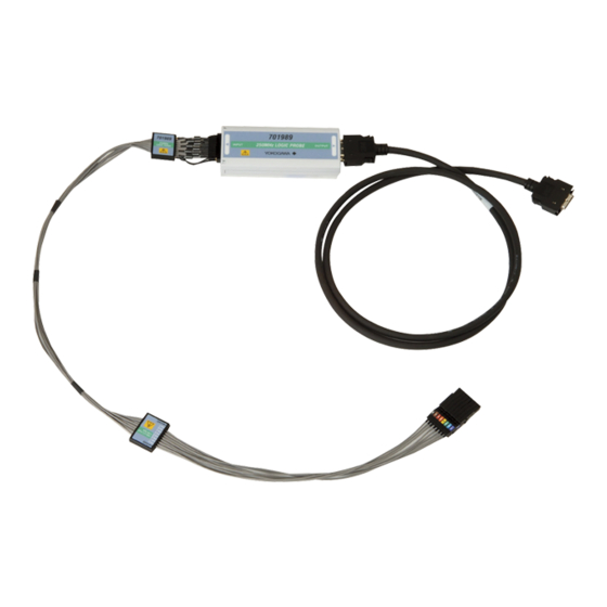
The PBL250 is an 8-bit input logic probe with a maximum toggle frequency of 250 MHz that is used with oscillscopes equipped with logic input. * For oscilloscope models that are compatible with this instrument, please contact your nearest YOKOGAWA representative. Features • High input impedance (100 kΩ, 3 pF: each input terminal to ground) •... -
Page 12: Names And Functions Of Parts
The points of connection for 250 mm GND leads. They are of the same electric potential as the GND terminals on the ends of the leads and the grounding of the connected oscilloscope. Cable Connects to the oscilloscope’s logic signal input port. IM 701989-01E... -
Page 13: Usage Precautions
Connect the logic probe’s cable to the oscilloscope’s logic signal input port. Connect the logic probe’s probe and GND leads to the circuit under test. * For oscilloscope models that are compatible with this logic probe, please contact your nearest YOKOGAWA representative. IM 701989-01E... - Page 14 Usage Example Connecting Directly to 2.54 mm Pitch Pin Headers on the PCB Probe head Connection Using a 75 mm GND Lead GND lead Removable GND terminal Connects to a separated GND using a 75 mm GND lead IM 701989-01E...
- Page 15 250 mm GND lead Connecting to an IC Using Microclips Connect a 50 mm clip lead to the signal input terminal and a 75 mm GND lead to the GND terminal, then connect microclips to the ends of both leads. IM 701989-01E...
- Page 16 Connection Using a 250 mm GND Lead (Inserting/Removing Multiple Bits at Once) Connect a 250 mm GND lead to a common GND terminal, then connect to GND on the PCB. Using a longer GND lead lowers performance. Common GND terminal 250 mm GND lead IM 701989-01E...
- Page 17 Using a longer GND lead lowers performance. Common GND terminal 250 mm GND lead Connection Using a Stacking Spacers When stacking the probe heads, you can connect probe heads to only the desired pins by using stacking spacers. Stacking spacers IM 701989-01E...
-
Page 18: Product Specifications
1 ns 1. See derating of input voltage by frequency 2. Standard operating conditions, after warm-up. 3. A typical value is a typical or average value. It is not strictly guaranteed. Input voltage derating by frequency 1000 Frequency (MHz) IM 701989-01E... - Page 19 Connected to the DLM2000 series mixed signal oscilloscope, with the logic probe’s lead set terminated at 50 Ω. Cable condition Attach a ferrite core (TDK: ZCAT2035-0930A, YOKOGAWA part number: A1190MN) to both ends of the cable (see figure below). 6 For conformity to environmental regulations and/or standards other than EU, contact your nearest YOKOGAWA office (PIM113-01Z2).
- Page 20 Cable (1 m) B8099BZ Replacing the Probe Lead Set Remove the probe lead set from the logic probe, then align the new probe lead set with the guide on the probe and insert as shown in the figure below. Guide IM 701989-01E...