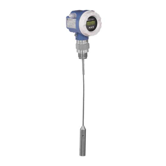
Endress+Hauser Levelflex M FMP 40 Operating Instructions Manual
Fmp 40 with profibus-pa guided level-radar
Hide thumbs
Also See for Levelflex M FMP 40:
- Manual (84 pages) ,
- Operating instructions manual (108 pages)

Related Manuals for Endress+Hauser Levelflex M FMP 40


Summary of Contents for Endress+Hauser Levelflex M FMP 40
- Page 1 levelflex M BA 243F/00/en/02.03 Nr. 52011932 FMP 40 with PROFIBUS-PA Valid as of software version: V 01.02.00 (amplifier) V 01.02.00 (communication) Guided Level-Radar Operating Instructions...
- Page 2 Brief operating instructions Levelflex M FMP 40 with PROFIBUS-PA Brief operating instructions KA 189F/00/a2/03.02 Levelflex M - Brief operating instructions 52012501 Contrast: measured value dist./ meas value Group selection basic setup tank medium process empty full dist./ check range of...
-
Page 3: Table Of Contents
Cable specifications PROFIBUS ..30 Contact addresses of Endress+Hauser ..89 Connecting the measuring unit ... 31 Equipotential bonding . -
Page 4: Safety Instructions
Levelflex M FMP 40 with PROFIBUS-PA Safety instructions Designated use The Levelflex M FMP 40 is a compact level transmitter for the continuous measurement of solids and liquids, measuring prinziple: Guided Level Radar / TDR: Time Domain Reflectometry). Installation, commissioning and operation The Levelflex M has been designed to operate safely in accordance with current technical, safety and EU standards. -
Page 5: Notes On Safety Conventions And Symbols
Levelflex M FMP 40 with PROFIBUS-PA 1 Safety instructions Notes on safety conventions and symbols In order to highlight safety-relevant or alternative operating procedures in the manual, the following conventions have been used, each indicated by a corresponding symbol in the margin. -
Page 6: Identification
Patents see sep. label Dat./Insp.: D01301-A Reference to additional safety-relevant documentation Fig. 1 Information on the nameplate of the Levelflex M FMP 40 (example) 2.1.2 Ordering structure Ordering structure Levelflex M FMP 40 Certificates A For non-hazardous areas M FM DIP, Class II, Division 1, Group E-G N.I. - Page 7 Levelflex M FMP 40 with PROFIBUS-PA 2 Identification Probe length Rope probes: 1000 mm...35000 mm / 40 in...1378 in A mm, 4 mm rope, 316 B mm, 6 mm rope, 316 C in, 1/6" rope, 316 D in, 1/4" rope, 316 Rod probes: min.
- Page 8 2 Identification Levelflex M FMP 40 with PROFIBUS-PA Display without display with display VU 331 incl. on-side operation Special version Remote electronic 1 Standard compact device 2 distance sleeve 400 mm for electronic 3 remote electronic, 3 m cable 9 Special version...
-
Page 9: Scope Of Delivery
"Protection Measures for Electrical Equipment for Measurement, Control, Regulation and Laboratory Procedures". The instrument described in this manual thus complies with the statutory requirements of the EG directives. Endress+Hauser confirms the successful testing of the instrument by affixing to it the CE mark. -
Page 10: Mounting
3 Mounting Levelflex M FMP 40 with PROFIBUS-PA Mounting Quick installation guide F12 or T12 housing Turn housing The housing can be turned 350° in order to simplify access to the display and the terminal compartment ½ 1 " F12 housing... -
Page 11: Incoming Acceptance, Transport, Storage
Levelflex M FMP 40 with PROFIBUS-PA 3 Mounting Incoming acceptance, transport, storage 3.2.1 Incoming acceptance Check the packing and contents for any signs of damage. Check the shipment, make sure nothing is missing and that the scope of supply matches your order. -
Page 12: Installation Conditions
3 Mounting Levelflex M FMP 40 with PROFIBUS-PA Installation Conditions 3.3.1 Dimensions F12 housing T12 housing ca. 86 ENDRESS+HAUSER ENDRESS+HAUSER Levelflex-M Levelflex-M option: option: remote electronic distance sleeve 4 x Ø 8,5 Ø 60,3 Ø 76 Ø 76 Threaded connection Flange DN 40…200... -
Page 13: Installation
Levelflex M FMP 40 with PROFIBUS-PA 3 Mounting Installation 3.4.1 Mounting kit In addition to the tool needed for flange mounting, you will require the following tool: • 4 mm Allen wrench for turning the housing. Shortening probes Rod and rope probes can be easily shortened. This is necessary if the distance to the container floor or outlet cone is less than 150 mm in the case of a rope probe, or less than 100 mm in the case of a rod probe or less than 50 mm in the case of a coax probe. - Page 14 3 Mounting Levelflex M FMP 40 with PROFIBUS-PA 3.4.2 Engineering hints for level measurement in bulk solids and fluids The following installation instructions apply for rope and rod probes for measurement in bulk solids and fluids. Coax probes are suitable purely for measurement in fluids. They function practically independent of all installation conditions and can, therefore, be installed as desired.
- Page 15 Levelflex M FMP 40 with PROFIBUS-PA 3 Mounting Other installations • Select the mounting location such that the distance to internals (5) (e.g. limit switch, struts) > is 300 mm over the entire length of the probe, also during operation.
- Page 16 3 Mounting Levelflex M FMP 40 with PROFIBUS-PA Standard installation • Probes are mounted to the process connection with threaded connections or flanges and are usually also secured with these. If during this installation there is the danger that the probe end moves so much that it touches the tank floor or cone at times, the probe must, if necessary, be shortened and fixed down.
- Page 17 Levelflex M FMP 40 with PROFIBUS-PA 3 Mounting 3.4.3 Special notes for bulk solids • In the case of bulk solids, as great a distance as possible from the filling curtain is especially important to avoid wear. • In concrete silos, a large distance (B) should be observed between the probe and the concrete wall, if possible >= 1m,...
- Page 18 3 Mounting Levelflex M FMP 40 with PROFIBUS-PA 3.4.4 Installation in bulk solid silos Tensile load Bulk solids exert tensile forces on rope probes whose height increases with:: • the length of the probe, i.e. max. cover, • the bulk density of the product, •...
- Page 19 Levelflex M FMP 40 with PROFIBUS-PA 3 Mounting Since the tensile forces are also heavily dependent on the viscosity of the product, a higher safety factor is necessary for highly viscous products and if there is a risk of cornice build-up.
- Page 20 3 Mounting Levelflex M FMP 40 with PROFIBUS-PA 3.4.5 Installation in liquids tanks • When installing in agitation units, check whether a no-contact process (ultrasonic or radar) would be better suited, especially if the agitator generates large mechanical loads on the probe.
- Page 21 Levelflex M FMP 40 with PROFIBUS-PA 3 Mounting Installation in underground tanks • Use coax probe for nozzles with large diameters in order to avoid reflections at the nozzle wall. Measurement in corrosive fluids For measurement in corrosive liquids, it is possible to install a rod probe in a closed plastic pipe with a diameter of up to approx.
- Page 22 3 Mounting Levelflex M FMP 40 with PROFIBUS-PA Mounting Location • Recommended distance B wall- mounted rope probe: ~1/6...1/4 of the container diameter (min. 100 mm/4", concrete silos: min. 500 mm). • Not central (2) in metallic tanks. • Not in the filling curtain (3).
- Page 23 Levelflex M FMP 40 with PROFIBUS-PA 3 Mounting 3.4.6 Notes on special installation situations Fixing rope probe • The end of the probe needs to be secured if the probe would otherwise touch the silo wall, the cone or another part, or the probe comes closer than 0.5...
- Page 24 3 Mounting Levelflex M FMP 40 with PROFIBUS-PA Installation from the side • If installation from above is not possible, the Levelflex can also be mounted from the side. • In this case, always fix the rope probe (see »Fixing rope probe« ).
- Page 25 Levelflex M FMP 40 with PROFIBUS-PA 3 Mounting • If measuring externally, an automatic probe length determination and a two point linearisation must be performed in order to compensate for the time-of-flight change caused by the plastic wall. Installation in nozzles > 150 mm high If, when installing probes in nozzles DN 40...250/1 ½"...10"...
- Page 26 3 Mounting Levelflex M FMP 40 with PROFIBUS-PA Installation in > DN 300/DN 12" nozzles If installation in > 300mm/12" nozzles is unavoidable, installation must be carried out in accordance with the sketch on the pipe right. Ø 150 … 180 Approx.
- Page 27 Levelflex M FMP 40 with PROFIBUS-PA 3 Mounting Installation with separate housing • Follow installation instructions on Page 14 ff.. • Mount housing on a wall or pipe as shown in the diagram. wall ENDRESS+HAUSER Levelflex M 4 x Ø 8,5...
-
Page 28: Post-Installation Check
3 Mounting Levelflex M FMP 40 with PROFIBUS-PA 3.4.8 Turn housing After mounting, the housing can be turned 350° in order to simplify access to the display and the terminal compartment. Proceed as follows to turn the housing to the required position: •... -
Page 29: Wiring
Levelflex M FMP 40 with PROFIBUS-PA 4 Wiring Wiring Quick wiring guide Wiring in F12 housing Before connection please note the following: " PROFIBUS devices are marked on the nameplate (1). The voltage is determined by the PROFIBUS standard and the... -
Page 30: Cable Specifications Profibus
4 Wiring Levelflex M FMP 40 with PROFIBUS-PA Wiring with M12 connector Before connection please note the following: " PROFIBUS devices are marked on the nameplate (1). The voltage is determined by the PROFIBUS standard and the Caution! desired safety concept. (see chapter 4.3). -
Page 31: Connecting The Measuring Unit
Levelflex M FMP 40 with PROFIBUS-PA 4 Wiring Connecting the measuring unit Housing Housing orientation regarding the wiring, see »Turn housing« on page 28. Cable entry Cable gland: M20x1.5 or Pg13.5 Cable entry: G ½ or ½" NPT PROFIBUS-PA M12 plug... -
Page 32: Equipotential Bonding
4 Wiring Levelflex M FMP 40 with PROFIBUS-PA Equipotential bonding For maximum protection against electromagnetic interference, e.g. when the bus is operating near frequency converters, it is recommended that high integrity potential bonding be provided between the housing and the cable screening. Transposed, screened two-wire cabling is recommended for the connecting cable. -
Page 33: Operation
Levelflex M FMP 40 with PROFIBUS-PA 5 Operation Operation Quick operation guide ENDRESS + HAUSER – >3 s Selection and configuration in Operation menu: 1.) Change from Measured Value Display to Group Selection by pressing 2.) Press to select the required Function Group (e.g.. - Page 34 5 Operation Levelflex M FMP 40 with PROFIBUS-PA 5.1.1 General structure of the operating menu The operating menu is made up of two levels: • Function groups (00, 01, 03, …, 0C, 0D): The individual operating options of the instrument are split up roughly into different function groups.
-
Page 35: Display And Operating Elements
Levelflex M FMP 40 with PROFIBUS-PA 5 Operation Display and operating elements Orde Orde Ser.- Ser.- r Cod r Cod No.: No.: sber surin sber surin eich eich g rang g rang U 16... U 16... 4...2 4...2 0 mA... - Page 36 5 Operation Levelflex M FMP 40 with PROFIBUS-PA 5.2.2 Display symbols The following table describes the symbols that appear on the liquid crystal display: Symbols Meaning ALARM_SYMBOL This alarm symbol appears when the instrument is in an alarm state. If the symbol flashes, this indicates a warning.
-
Page 37: Local Operation
Levelflex M FMP 40 with PROFIBUS-PA 5 Operation Local operation 5.3.1 Locking of the configuration mode The Levelflex can be protected in two ways against unauthorised changing of instru- ment data, numerical values or factory settings: "unlock parameter" (0A4): A value <> 2457 (e.g. 2456) must be entered in "unlock parameter" (0A4) in the "diagnostics"... - Page 38 There is no need to change these parameters under normal circumstances and conse- quently, they are protected by a special code known only to the E+H service organiza- tion. Please contact Endress+Hauser if you have any questions. Endress+Hauser...
- Page 39 Levelflex M FMP 40 with PROFIBUS-PA 5 Operation 5.3.3 Factory settings (Reset) " Caution! A reset sets the instrument back to the factory settings. This can lead to an impairment of the measurement. Generally, you should perform a basic setup again following a reset.
-
Page 40: Display And Acknowledging Error Messages
5 Operation Levelflex M FMP 40 with PROFIBUS-PA Display and acknowledging error messages Type of error Errors that occur during commissioning or measuring are displayed immediately on the local display. If two or more system or process errors occur, the error with the highest priority is the one shown on the display. -
Page 41: Profibus Communication
Levelflex M FMP 40 with PROFIBUS-PA 5 Operation PROFIBUS communication 5.5.1 Synopsis personal computer e.g. with Commuwin II or ToF Tool and Profibard resp. Proficard segment coupler PROFIBUS-DP ENDRESS + HAUSER PROFIBUS-PA operating and display module VU 331 More ENDRESS + HAUSER –... - Page 42 5 Operation Levelflex M FMP 40 with PROFIBUS-PA 5.5.2 Device address Selecting the device address • Every PROFIBUS-PA device must be given an address. If the address is not set correctly, the device will not be recognised by the process control system.
- Page 43 Levelflex M FMP 40 with PROFIBUS-PA 5 Operation 5.5.3 Device database and type files (GSD) A device database file (GSD) contains a description of the properties of the PROFIBUS- PA device, e.g. the supported transmission rates and the type and format of the digital information output to the PLC.
- Page 44 5.5.4 Cyclic data exchange Block model of the Levelflex M FMP 40 The block model shows, which data are exchanged continously (i.e. by cyclic data transfer) between the Levelflex M and the PLC. The numbers refer to the function groups and functions (see page 94): •...
- Page 45 Levelflex M FMP 40 with PROFIBUS-PA 5 Operation Configuration of the cyclic data telegram Use the configuration software of your PLC in order to compose the data telegram from these modules in one of the following ways: 1. Main value In order to transmit the main measured value, selct the module Main Process Value.
- Page 46 5 Operation Levelflex M FMP 40 with PROFIBUS-PA IEEE-745 Floating Point Number The measured value is transmitted as a IEEE 754 floating point number, whereby (E-127) Measured value = (-1) x (1+F) Byte 1 Byte 2 Bit 7 Bit 6 Bit5...
- Page 47 Levelflex M FMP 40 with PROFIBUS-PA 5 Operation Stauts codes The status codes comprise one byte and have got the following meaning: Status- Device status Significance Primary Secondary Code value value 0C Hex device error 0F Hex device error 1F Hex...
- Page 48 5 Operation Levelflex M FMP 40 with PROFIBUS-PA 5.5.5 Acyclic data exchange The device parameters in the physical block, transducer block and analog input block, as well as the device management can be accessed by a Class 2 PROFIBUS-DP master (e.g. Commuwin II) using the acyclic data services.
- Page 49 Levelflex M FMP 40 with PROFIBUS-PA 5 Operation Parameter E+H Matrix Slot Index Size Type Read Write Storage (CW II) [bytes] Class LO Limit FLOAT static LO LO Limit FLOAT static 44-45 HI HI Alarm DS-39* dynamic HI Alarm DS-39*...
- Page 50 5 Operation Levelflex M FMP 40 with PROFIBUS-PA Parameter E+H Matrix Slot Index Size Type Read Write Storage (CW II) [bytes] Class Up Down features OSTRING constant Up Down control UNSIGNED8 dynamic Up Down param OSTRING dynamic Bus address UNSIGNED8 dynamic Device SW No.
- Page 51 Levelflex M FMP 40 with PROFIBUS-PA 5 Operation Parameter E+H Matrix Slot Index Size Type Read Write Storage (CW II) [bytes] Class 163-167 Level/ullage V3H0 UNSIGNED8 static Linearisation mode V3H1 UNSIGNED8 static Customer unit V3H2 UNSIGNED16 static Table no. V3H3...
- Page 52 5 Operation Levelflex M FMP 40 with PROFIBUS-PA Parameter E+H Matrix Slot Index Size Type Read Write Storage (CW II) [bytes] Class Tag no. VAH0 STRING const Profile revision VAH1 STRING static Version string VAH2 STRING const Serial no. VAH4...
- Page 53 Levelflex M FMP 40 with PROFIBUS-PA 5 Operation 5.5.6 Parameter access via Commuwin II The block parameters can be accessed by a PROFIBUS-DP Class 2 master, for example, Commuwin II. Commuwin II runs on an IBM-compatible computer or laptop. The computer must be equipped with a PROFIBUS interface, i.e. PROFIBOARD for PCs and PROFICARD for laptops.
- Page 54 5.5.7 Parameter access via ToF Tool The ToF Tool is a graphical operating software for instruments from Endress+Hauser that operate based on the time-of-flight principle. It is used to support commissioning, securing of data, signal analysis and documentation of the instruments. It is compatible with the following operating systems: Win95, Win98, WinNT4.0, Win2000 and...
- Page 55 Levelflex M FMP 40 with PROFIBUS-PA 5 Operation Signal analysis via envelope curve: Connection options: • Service-interface with adapter FXA 193 (see page 41) • Proficard for connection to a Laptop • Proficard for connection to a PC Note! The Levelflex M can also be operated locally using the keys. If operation is prevented by the keys being locked locally, parameter entry via communication is not possible either.
- Page 56 5 Operation Levelflex M FMP 40 with PROFIBUS-PA 5.5.8 Scaling of the output data The on-site display and the digital output are working independently of each other. On-site display The on-site display always displayes the main value V0H0 directly from the Transducer Block.
-
Page 57: Commissioning
Levelflex M FMP 40 with PROFIBUS-PA 6 Commissioning Commissioning Function check Make sure that all final checks have been completed before you start up your measuring point: • Checklist “Post installation check” (see page 28 ff.). • Checklist “Post connection check” (see page 32 ff.). -
Page 58: Basic Setup
6 Commissioning Levelflex M FMP 40 with PROFIBUS-PA Basic Setup flange: reference point of measurement E = empty calibr. (= zero) LN = probe length setting in 005 setting in 033 F = full calibr. (= span) UB = upper blocking distance... - Page 59 Levelflex M FMP 40 with PROFIBUS-PA 6 Commissioning The basic setup is sufficient for successful commissioning in most applications. Note! The Levelflex M allows to check for broken probe. On delivery, this function is switched off, because otherwise shortening of the probe would be mistaken for a broken probe.
-
Page 60: Basic Setup With The Vu 331
6 Commissioning Levelflex M FMP 40 with PROFIBUS-PA Basic Setup with the VU 331 Function "measured value" (000) ⇒ This function displays the current measured value in the selected unit (see "customer unit" (042) function). The number of digits after decimal point can be selected in the "no.of decimals"... - Page 61 Levelflex M FMP 40 with PROFIBUS-PA 6 Commissioning bypass / pipe The "bypass / pipe" option is designed especially for the installation of probes in a bypass or a stilling well. coax probe Select the "coax probe" option when using a coaxial probe. When this setting is made, the evaluation is adapted to the high sensitivity of the coax probe.
- Page 62 6 Commissioning Levelflex M FMP 40 with PROFIBUS-PA Function "process propert." (004) ⇒ Use this function to adapt the device reaction to the filling speed in the tank. The setting impacts on an intelligent filter. Selection: • standard • fast change •...
- Page 63 Levelflex M FMP 40 with PROFIBUS-PA 6 Commissioning Function "probe length" (031) ⇒ Use this function to select whether the probe length was changed after factory calibration. Only then is it necessary to enter or correct the probe length. Selection: •...
- Page 64 6 Commissioning Levelflex M FMP 40 with PROFIBUS-PA Function "empty calibr." (005) ⇒ This function is used to enter the distance from the flange (reference point of the measurement) to the minimum level (=zero). E = empty calibration (= zero) E max = probe length –...
- Page 65 Levelflex M FMP 40 with PROFIBUS-PA 6 Commissioning Note! The usable measuring range lies between the lower and the upper blocking distance. The values for empty distance (E) and span (F) can be set independently of this. Blocking distance and measuring range for Dk ≥ 1.6 (1.4 for coax probes): LN [m]/"...
- Page 66 6 Commissioning Levelflex M FMP 40 with PROFIBUS-PA Display (008) ⇒ The distance measured from the reference point to the product surface and the meas. value calculated with the aid of the empty adjustment are displayed. Check whether the values correspond to the actual meas. value or the actual distance. The following cases can occur: •...
- Page 67 Levelflex M FMP 40 with PROFIBUS-PA 6 Commissioning dist. too small • At the moment, an interference is being evaluated • Therefore, a mapping is carried out including the presently measured echoes • The range to be suppressed is suggested in the "range of mapping (052)" function.
-
Page 68: Blocking Distnace
6 Commissioning Levelflex M FMP 40 with PROFIBUS-PA Display (008) ⇒ The distance measured from the reference point to the product surface and the meas. value calculated with the aid of the empty alignment are displayed again. Check whether the values correspond to the actual meas. value or the actual distance. The following cases can occur: •... -
Page 69: Envelope Curve With Vu 331
Levelflex M FMP 40 with PROFIBUS-PA 6 Commissioning Envelope curve with VU 331 After the basic setup, an evaluation of the measurement with the aid of the envelope curve ("envelope curve" (0E) function group) is recommended.). 6.6.1 Function "plot settings" (0E1) ⇒... -
Page 70: Function "Envelope Curve Display" (0E3)
6 Commissioning Levelflex M FMP 40 with PROFIBUS-PA Function "envelope curve display" (0E3) You can obtain the following information from the envelope curve display in this function: quality of evaluated echo full calibr. evaluated echo empty calibr. is marked envelope curve... - Page 71 Levelflex M FMP 40 with PROFIBUS-PA 6 Commissioning Horizontal-Zoom-Modus Press , to switch to the envelope curve navigation. You are then in Horizontal Zoom mode. Either is displayed. You now have the following options: • increases the horizontal scale. •...
-
Page 72: Basic Setup With The Tof Tool
6 Commissioning Levelflex M FMP 40 with PROFIBUS-PA Basic Setup with the ToF Tool To carry out the basic setup with the ToF Tool operating program, proceed as follows: • Start the ToF Tool operating program and establish a connection •... - Page 73 Levelflex M FMP 40 with PROFIBUS-PA 6 Commissioning Basic Setup step 2/5: • Enter the application parameters: – tank properties (for a description, see page 60) – medium properties (for a description, see page 61) – process properties(for a description, see page 62) Basic Setup step 3/6: •...
- Page 74 6 Commissioning Levelflex M FMP 40 with PROFIBUS-PA Basic Setup step 4/6: • Enter the application parameters: – probe (for a description, see page 63) – probe length (for a description, see page 63) – determine length (for a description, see page 63) Basic Setup step 5/6: •...
- Page 75 Levelflex M FMP 40 with PROFIBUS-PA 6 Commissioning Basic Setup step 6/6: • This step starts the tank mapping • The measured distance and the current measured value are always displayed in the header • for a description, see page 66...
- Page 76 6 Commissioning Levelflex M FMP 40 with PROFIBUS-PA 6.8.2 Envelope curve with the ToF Tool After the basic setup, an evaluation of the measurement using the envelope curve is recommended. Note! For the optimization of the measurement the installation of the Levelflex in another place can be executed when enterference echoes.
-
Page 77: Maintenance
They contain the related replacement instructions. All the spare parts kits which you can order from Endress+Hauser for repairs to the Levelflex M are listed with their order numbers on pages 87 and 88. sind alle Ersatzteil- Kits mit Bestellnummern aufgeführt, die Sie zur Reparatur des Levelflex M bei... -
Page 78: Accessories
8 Accessories Levelflex M FMP 40 with PROFIBUS-PA Accessories Various accessories, which can be ordered separately from Endress+Hauser, are available for the Levelflex M. Weather protection cover A Weather protection cover made of stainless steel is available for outdoor mounting (order code: 543199-0001). - Page 79 Levelflex M FMP 40 with PROFIBUS-PA 8 Accessories Flange with horn adapter to adapt on the following nozzles Order - No. G 1 1/2" at DN 200 / PN 16 52014251 G 1 1/2" at DN 250 / PN 16 52014252 NPT 1 1/2"...
- Page 80 8 Accessories Levelflex M FMP 40 with PROFIBUS-PA Isolated tie down Order - No. for 4mm rope probe 52014249 Reliable, isolated mounting for 6mm rope probe 52014250 If a rope probe has to be fixed and a secure grounded mounting is not...
- Page 81 Levelflex M FMP 40 with PROFIBUS-PA 8 Accessories Remote display FHX 40 Dimensions F12 housing (IP 68) Separate housing FHX 40 (IP 65) O rd O rd r. -N r. -N d e : d e : o .: o .:...
-
Page 82: Trouble-Shooting
9 Trouble-shooting Levelflex M FMP 40 with PROFIBUS-PA Trouble-shooting Trouble-shooting instructions Levelflex M FMP 40 -Trouble Shooting Check voltage and Not ok compare it with the Instrument does Connect the Instrument works? Ready specifications on the not respond correct voltage nameplate. -
Page 83: System Error Messages
Levelflex M FMP 40 with PROFIBUS-PA 9 Trouble-shooting System error messages Code Description Possible cause Remedy A102 checksum error device has been powered off reset; general reset & new before data could be stored; emc avoid emc problem; if alarm calibr.required... - Page 84 9 Trouble-shooting Levelflex M FMP 40 with PROFIBUS-PA Code Description Possible cause Remedy A241 Broken probe Broken probe or Check the probe length in value for probe length is too short 033, Check the probe itself, if the probe is broken,...
-
Page 85: Application Errors
Levelflex M FMP 40 with PROFIBUS-PA 9 Trouble-shooting Application errors Error Output Possible cause Remedy A warning or Depending on the configuration See table of 1. See table of error messages alarm has error messages (see page 83) occurred. (see page 83) →... - Page 86 9 Trouble-shooting Levelflex M FMP 40 with PROFIBUS-PA Device displays a Incorrect probe 1. Carry out automatic probe length level when the length detection when the tank is empty. tank is empty. 2. Carry out mapping over entire probe 20 mA/100% when the tank is empty (probe free).
-
Page 87: Spare Parts
The corresponding spare part number also appears on each spare part. Installation instructions are given on the instruction card that is also delivered. Spare parts Levelflex M FMP 40 with housing F12 Only identical, original E+H spare parts may be used. - Page 88 9 Trouble-shooting Levelflex M FMP 40 with PROFIBUS-PA Spare parts Levelflex M FMP 40 - probes and accessories M IC M IC O rd O rd S er S er C od C od P IL P IL o. : o.
-
Page 89: Return
(from OS 4.6) with Rev. 1, DD 1. Contact addresses of Endress+Hauser The addresses of Endress+Hauser are given on the back cover of this operating manual. If you have any questions, please do not hesitate to contact your E+H representative. -
Page 90: Technical Data
10 Technical data Levelflex M FMP 40 with PROFIBUS-PA Technical data 10.1 Technical data at a glance Application Application The Levelflex M performs continuous level measurement of powdery to granular bulk solids and liquids e.g. plastic granulate. Probes are available with threaded process connections from ¾"... - Page 91 Levelflex M FMP 40 with PROFIBUS-PA 10 Technical data Performance characteristics Reference operating • temperature = +20 °C (68 °F) ±5 °C (9 °F) conditions • pressure = 1013 mbar abs. (14.7 psia) ±20 mbar (0.3 psi) • relative humidity (air) = 65 % ± 20% •...
- Page 92 NAMUR Standards committee for measurement and control in the chemical industry Ex approval see »Ordering structure Levelflex M FMP 40« on page 6 Ordering Information The E+H service organisation can provide detailed ordering information an information on the order codes on request.
- Page 93 Levelflex M FMP 40 with PROFIBUS-PA 10 Technical data Supplementary Documentation Supplementary Docu- • System Information Levelflex (SI 030F/00/en) mentation • Technical Information (TI 358F/00/en) • Operating Instructions "Description of instrument functions" (BA 245F/00/en) Endress+Hauser...
-
Page 94: Appendix
11 Appendix Levelflex M FMP 40 with PROFIBUS-PA Appendix 11.1 Operating menu HART (Display modul), ToF Tool basic setup tank properties medium cond. process proper. end of probe 030 determine length empty calibr. enter value standard unknown standard see Function group “leghth adjustment 03”... - Page 95 Levelflex M FMP 40 with PROFIBUS-PA 11 Appendix full calibr. dist./meas.value check distance range of mapping start mapping dist./meas.value enter value distance = ok input of D and L dist. too small mapping range are displayed D and L manual...
-
Page 96: Operating Matrix Profibus-Pa / Commuwin Ii
11 Appendix Levelflex M FMP 40 with PROFIBUS-PA 11.2 Operating matrix PROFIBUS-PA / Commuwin II Endress+Hauser... -
Page 97: 11.3 Description Of Functions
Levelflex M FMP 40 with PROFIBUS-PA 11 Appendix 11.3 Description of functions Note! A detailed description of the function groups, functions and parameters is given in the documentation BA 245F/00/en - a description of the instrument functions of the Levelflex M. -
Page 98: 11.4 Function And System Design
11 Appendix Levelflex M FMP 40 with PROFIBUS-PA 11.4 Function and system design 11.4.1 Measuring principle The Levelflex is a "downward-looking" measuring system that functions according to the ToF method (ToF = Time of Flight). The distance from the reference point (process connection of the measuring device see page 12) to the product surface is measured. - Page 99 Levelflex M FMP 40 with PROFIBUS-PA 11 Appendix Output The Levelflex is initially adjusted at the factory to the probe length ordered, so that in most cases only the application parameters, that automatically adapt the device to the measuring conditions, need to be entered. For models with current output, the factory adjustment for zero point and span is F 4 mA and 20 mA, for digital outputs and the display module 0 % and 100 %.
- Page 100 11 Appendix Levelflex M FMP 40 with PROFIBUS-PA Evaluation of the measurement: • The map must correspond to the course of the envelope curve (for rod probes up to approx. 5 cm and for rope probes up to approx. 25 cm before the end of the probe) when the tank is empty.
- Page 101 • with display and operating module VU 331, • with a Personal Computer, FXA 193 and the operating software ToF Tool. The ToF Tool is a graphical operating software for instruments from Endress+Hauser that operate based on the time-of-flight principle (radar, ultrasonic, guided micro- impulse).
- Page 102 11 Appendix Levelflex M FMP 40 with PROFIBUS-PA This product may be protected by at least one of the following patents. Further patents are pending. • US 5,345,471 EP 0 694 235 (under Licence) • US 5,517,198 (under Licence) • US 5,661,251 EP 0 780 664 •...
- Page 103 Levelflex M FMP 40 with PROFIBUS-PA 11 Appendix Endress+Hauser...
-
Page 104: Index
Index Levelflex M FMP 40 with PROFIBUS-PA Index Menue structure ......94 Mounting ....... . . 10 Accessories. - Page 105 Levelflex M FMP 40 with PROFIBUS-PA Index Wiring ........29...
- Page 106 Index Levelflex M FMP 40 with PROFIBUS-PA Endress+Hauser...
- Page 107 Levelflex M FMP 40 with PROFIBUS-PA Index Declaration of contamination Dear costumer, Because of legal determinations and for the safety of our employes and operating equipment we need this “Declaration of contamination” with your signature before your order can be handled. Please put the completely filled in declaration to the instrument and to the shipping documents in any case.
- Page 108 Belorgsintez Canada Philippines Poland Minsk Endress+Hauser Ltd. Endress+Hauser Philippines Inc. Endress+Hauser Polska Sp. z o.o. Tel. (0172) 263166, Fax (0172) 263111 Burlington, Ontario Metro Manila Warszawy Tel. (905) 6819292, Fax (905) 6819444 Tel. (2) 3723601-05, Fax (2) 4121944 Belgium / Luxembourg Tel.