Advertisement
Quick Links
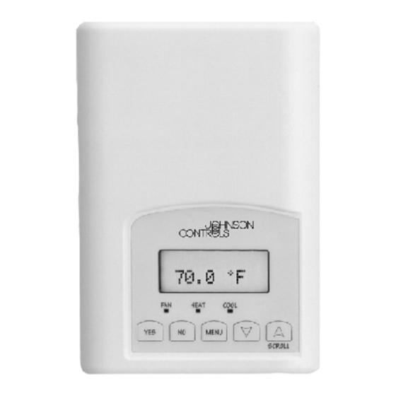
TEC2104-1 Networked Multi-Stage Economizer Thermostat
Application
The TEC2104-1 is an N2 networked thermostat that
provides control of single- or two-stage unitary rooftop
units with economizers. The TEC2104-1 provides
exceptional accuracy through the use of a unique
Proportional-Integral (PI) time proportioning algorithm.
The algorithm virtually eliminates temperature offset
associated with traditional, differential-based on/off
thermostats. The TEC2104-1 also uses an adaptive
control logic algorithm to control the space
temperature during recovery to minimize overshoot
while providing maximum comfort. Economizer
functions include a 0 to 10 VDC control signal,
dry-bulb changeover strategy, adjustable minimum
position, and mixed air setpoint control.
The TEC2104-1 has Metasys® N2 communication
capability. This communication allows the user to view
and adjust parameters from a remote workstation.
Additionally, the menu-driven backlit display, plain text
menus, and five keys on the TEC2104-1 make
operating the thermostat easy and intuitive.
Note: In this document, Building Automation System
(BAS) is a generic term that refers to the Metasys
Network (Network Control Module [NCM] or
N30 Series) and Companion (CPN) supervisory
systems. The specific system names are used when
referring to system-specific applications.
Installation
Location Considerations
Locate the TEC2104-1 thermostat:
•
on a partitioning interior wall and approximately
5 ft. (1.5 m) above the floor in a location of
average temperature
•
away from direct sunlight, radiant heat, outside
walls, behind doors, air discharge grills, stairwells,
or outside doors
•
away from steam or water pipes, warm air stacks,
unheated/uncooled areas, or sources of electrical
interference
©
2004 Johnson Controls, Inc.
Part No. 24-9890-56, Rev. B
Installation Instructions
To install the thermostat:
1.
Remove the security screw on the bottom of the
thermostat cover using a Phillips-head
screwdriver. Open the thermostat by pulling on
the bottom side of the thermostat cover
(Figure 1).
2.
Unlock the Printed Circuit Board (PCB) by
carefully pressing the locking tabs to the right
(Figure 2). Open the thermostat's PCB to the left.
3.
Pull out approximately 6 in. (152 mm) of wires
from the wall and insert the cable through the
hole in the base.
4.
Align the base on the wall, and using the base as
a template, mark the location of the two mounting
holes on the wall. Confirm the thermostat base is
installed with the proper side up.
5.
Use the supplied anchors and screws for
mounting on drywall or plaster. Drill two 3/16 in.
(4.7 mm) holes at the marked locations and tap
nylon anchors flush to wall surface (Figure 3).
6.
Position base on the wall, insert screws through
mounting base, and fasten into wall anchors. Do
not overtighten screws.
7.
Swing the thermostat PCB back to the right to
close. Gently press on the PCB to secure each of
the locking tabs.
8.
Pull out the screw terminal blocks using the
pull-tabs on each connector (Figure 4).
Note: The number of terminals on the terminal
blocks varies depending on the TEC model.
IMPORTANT:
Use this TEC2104-1 networked
economizer thermostat only as an operating control.
Where failure or malfunction of the TEC2104-1 could
lead to personal injury or property damage to the
controlled equipment or other property, additional
precautions must be designed into the control
system. Incorporate and maintain other devices such
as supervisory or alarm systems or safety or limit
controls intended to warn of, or protect against,
failure or malfunction of the TEC2104-1.
Issue Date August 18, 2004
www.johnsoncontrols.com
1
Advertisement

Related Manuals for Johnson Controls TEC2104-1


Summary of Contents for Johnson Controls TEC2104-1
- Page 1 Issue Date August 18, 2004 TEC2104-1 Networked Multi-Stage Economizer Thermostat Application The TEC2104-1 is an N2 networked thermostat that To install the thermostat: provides control of single- or two-stage unitary rooftop Remove the security screw on the bottom of the units with economizers.
- Page 2 CAUTION: Risk of Property Damage. Do not apply power to the system before checking all wiring connections. Short circuited or improperly Figure 3: Mounting the Thermostat Base connected wires may result in permanent damage to the equipment. TEC2104-1 Networked Multi-Stage Economizer Thermostat Installation Instructions...
- Page 3 When adding the TEC2104-1 to the Metasys system (Person-Machine Interface [PMI] and Companion 1. Observe the polarity when connecting the N2 Bus system), you must define the TEC2104-1 as a Vendor wires to the TEC2104-1. Device (VND). For the NCM, except as noted in Table 1, Footnote c, do not direct map any points.
- Page 4 CSBD 0 = Off, 1 = On a, c 0 = °C, 1 = °F Temp Units BD-9 N2 BO (Local Display Only) Footnote c. Continued on the next page . . . TEC2104-1 Networked Multi-Stage Economizer Thermostat Installation Instructions...
- Page 5 The setpoints can be spread further apart but can never be adjusted closer than 2°F apart. Failure to stay within the limits for a command results in an N2 Negative Acknowledge (NAK) error from the TEC2104-1. Overrides take precedence over any local adjustment or command in the TEC2104-1.
-
Page 6: Setup And Adjustments
Figure 6: TEC2104-1 Front Cover Thermostat Interface Keys The TEC2104-1 interface consists of five keys on the front cover and one configuration key (Figure 7) that is accessed by removing the front cover. The functions of the keys are as follows. - Page 7 Setpoint (Heat max) section. Configuring the TEC2104-1 Sets the Minimum Cooling Setpoint Cool min The TEC2104-1 ships from the factory with default Default: 54.0°F (12.0°C) set? Y/N settings for all configurable parameters. The default See the Setting the Minimum Cooling Setpoint (Cool min) section.
- Page 8 Default: Two Stages set? Y/N Displays the Mixed Air Temperature See the Disable/Enable Second Display Default: N/A Heating Stage (H Stage) section. MS? Y/N See the Displaying the Mixed Air Temperature (Display) section. TEC2104-1 Networked Multi-Stage Economizer Thermostat Installation Instructions...
- Page 9 Enabling the Keypad Lockout (Lockout) Press the configuration menu access key. The first The TEC2104-1 has four levels of keypad lockout. The prompt is to program Digital Inputs DI1 and DI2. levels and degree of lockout are shown in Table 3.
- Page 10 Main User Menu. The CAUTION: Risk of Property Damage. parameter is adjustable from 40 to 90°F (4.5 to 32°C). Do not set the TEC2104-1 anti-short cycling timer to Note: When adjusting the temperature, holding the 0 minutes if the controlled equipment is not keys down changes the temperature by 5 F/C°...
- Page 11 2. Using the UP/DOWN arrow keys, select on or off. Press YES to store the selection. The display now shows the N2 address prompt. See the Setting the N2 Address (N2 addr) section for instructions. TEC2104-1 Networked Multi-Stage Economizer Thermostat Installation Instructions...
- Page 12 See the Auxiliary Temperature/Outdoor Air Sensor Note: Pressing the YES and NO keys Calibration (Cal OS) section for instructions. simultaneously for 5 seconds on the user interface of the TEC2104-1 temporarily displays the N2 address of Auxiliary Temperature/Outdoor Air Sensor the thermostat. Calibration (Cal OS)
- Page 13 -40 to 95°F (-40 to 35°C) in increments The display now shows the Mechanical Cooling Mode Menu. See the Setting the Mechanical Cooling Mode of 5 F/C°. (C mech) section for instructions. TEC2104-1 Networked Multi-Stage Economizer Thermostat Installation Instructions...
-
Page 14: Operation
2. The mixed air temperature is displayed. After about 45 seconds the TEC2104-1 returns to the To set the mechanical cooling mode while in the Status Display Menu or press YES to advance to Installer Configuration Menu: the exit menu display. - Page 15 Resuming the Programmed Schedule (only network, it appears the setpoint value can be changed appears when in the Override Mode) through the TEC2104-1, but the setpoint is actually still To resume the schedule while in the Main User Menu: held at the overridden value.
- Page 16 Press YES to return to the Status Exit? Unocc CL unoccupied cooling setpoint. Press Display Menu or NO to re-enter the set? Y/N NO to advance to the unoccupied temperature setting menu. heating setpoint. TEC2104-1 Networked Multi-Stage Economizer Thermostat Installation Instructions...
- Page 17 Off Mode (off) • Smart Fan Mode (smart) The TEC2104-1 is off. However, if frost protection Energizes the fan all the time for occupied periods is enabled and frost conditions are detected, the and only on a call for heat and cooling in thermostat still calls for heat even if the system unoccupied periods.
-
Page 18: Troubleshooting
Apply power to the TEC2104-1. N2 cable runs are broken. Locate and correct the wiring. Device type is incorrect. TEC2104-1 address must be VND device type. Entire N2 Bus is offline. EOL jumpers on MM-CVT101 or NCM are Install EOL jumpers properly. -
Page 19: Technical Specifications
The performance specifications are nominal and conform to acceptable industry standards. For application at conditions beyond these specifications, consult the local Johnson Controls office. Johnson Controls, Inc. shall not be liable for damages resulting from misapplication or misuse of its products.