Table of Contents
Advertisement
Available languages
Available languages
Quick Links
Owner's Manual
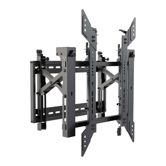
Portrait Video Wall
with Security
Model: DWMSCP4570VW
Español 17 • Français 33 • Русский 49 • Deutsch 65
CAUTION: DO NOT EXCEED MAXIMUM LISTED WEIGHT CAPACITY. SERIOUS INJURY OR PROPERTY DAMAGE MAY OCCUR!
200x200/300x300
200x400/400x400
400x600
WARRANTY REGISTRATION
Register your product today and be
automatically entered to win an ISOBAR
surge protector in our monthly drawing!
tripplite.com/warranty
1111 W. 35th Street, Chicago, IL 60609 USA • tripplite.com/support
Copyright © 2021 Tripp Lite. All rights reserved.
70"
MAX
®
1
154 lb.
154 lb.
(70 kg)
(70 kg)
RATED
RATED
Advertisement
Table of Contents

Related Manuals for Tripp Lite DWMSCP4570VW


Summary of Contents for Tripp Lite DWMSCP4570VW
- Page 1 WARRANTY REGISTRATION Register your product today and be automatically entered to win an ISOBAR ® surge protector in our monthly drawing! tripplite.com/warranty 1111 W. 35th Street, Chicago, IL 60609 USA • tripplite.com/support Copyright © 2021 Tripp Lite. All rights reserved.
-
Page 2: Important Safety Instructions
PRODUCT REGISTRATION Visit tripplite.com/warranty today to register your new Tripp Lite product. You’ll be automatically entered into a drawing for a chance to win a FREE Tripp Lite product!* * No purchase necessary. Void where prohibited. Some restrictions apply. See website for details. -
Page 3: Component Checklist
Component Checklist IMPORTANT: Ensure you have received all parts according to the component checklist prior to installing. If any parts are missing or faulty, visit tripplite.com/support for service. Wall Plate (x1) Pop-Out Module (x1) Adapter Bracket (x2) VESA Adapter (x2) VESA Adapter (x2) Lock (x1) Package P... - Page 4 1. Solid Brick and Concrete Wall Mounting WARNING Installers must verify that the supporting surface will safely support the combined weight of the equipment and all attached hardware and components. 2.4” 95 mm 95 mm (60 mm) (3.7") (3.7") Ø 3/8” (Ø...
- Page 5 2. Video Wall Installation (mounting space as shown below) X=Length of display Y=Height of display 3. Installing the Pop-Out Module Remove caps before installing the pop-out module.
- Page 6 3. Installing the Pop-Out Module Hang the pop-up module onto the wall plate. Secure it by tightening both screws. 4. Installing the Adapter Brackets For VESA hole patterns 400x400 or 600x400 Attach the VESA adapters to the adapter brackets using the appropriate screws and nuts so that the hole pattern can be expanded to VESA 400x400 or 600x400.
- Page 7 4. Installing the Adapter Brackets Top of the display 4.1 For Flat-Back Screens...
- Page 8 4.2 For Bump-Out or Recessed-Back Screens M-D M-E M-D M-E Notes: • Choose the appropriate screws, washers and spacers (if necessary) according to the type of screen. • Position the adapter brackets as close as possible to the center of the display. •...
- Page 9 5. Hooking the Display onto the Pop-Out Module Notes: • Before Hooking the display, ensure the knobs are rotated to the unlock position. • Lift the display carefully and hook it onto the pop-out module. Rotate the knobs to the lock position to secure the display. •...
- Page 10 6. Adjustment Push the display left or right for fast alignment. Handles for tilt adjustment Screws for up-and-down micro-adjustments Knobs for in-and-out micro-adjustments...
- Page 11 6. Adjustment Left Left Right Right Left Left Right Right...
- Page 12 6. Adjustment Left Left Right Right Left Left Right Right...
- Page 13 6. Adjustment Left Right Left Right wall wall wall To pop out the display, push it inward and then release it. Kickstands provide tilt access for easy cable management and maintenance.
- Page 14 7. Level the Displays Adjust the display to keep it level in vertical and horizontal directions.
- Page 15 7. Level the Displays Note: Use the plastic locking piece to measure and keep a 1.2 mm gap between displays. Note: Install and adjust displays in the numerical order shown.
- Page 16 8. Fixing the Bracket Positions with the Anti-Skid Blocks Install both of the anti-skid blocks as close to the adapter brackets as possible. Tighten screws on the anti-skid blocks using a hex key to prevent the display from moving. 9. Lock the Pop-Out Module with the Plastic Locking Pieces Top View Side View 1111 W.
-
Page 17: Manual Del Propietario
200x200 / 300x300 70" 70 kg 70 kg 200x400/400x400 [154 lb] [154 lb] MÁXIMO 400x600 CLASIFICADO CLASIFICADO MÁS DE AÑOS 1111 W. 35th Street, Chicago, IL 60609, EE. UU. • tripplite.com/support Copyright © 2021 Tripp Lite. Todos los derechos reservados. -
Page 18: Instrucciones De Seguridad Importantes
Tripp Lite tiene una política de mejora continua. Las especificaciones están sujetas a cambio sin previo aviso. Las imágenes pueden diferir ligeramente de los... - Page 19 Lista de Comprobación de Componentes IMPORTANTE: Antes de proceder a instalar, asegúrese de haber recibido todas las partes de acuerdo con la lista de comprobación de componentes. Si faltase alguna parte o estuviese dañada, visite tripplite.com/support para solicitar servicio. Placa de Pared (x1) Módulo Emergente (x1) Soporte Adaptador (x2) Adaptador VESA (x2)
- Page 20 1. Instalación sobre Pared de Ladrillo Sólido y Concreto ADVERTENCIA: Los instaladores deben verificar que la superficie de apoyo soporte con seguridad el peso combinado del equipo y de todo el hardware y componentes instalados. 2.4” 95 mm 95 mm (60 mm) (3.7") (3.7")
- Page 21 2. Instalación en Muro de Video (el espacio de instalación debe ser como se muestra a continuación) X=Longitud de la pantalla Y=Altura de la pantalla 3. Instalación del Módulo Emergente Retire los tapones antes de instalar el módulo emergente.
-
Page 22: Instalación De Los Soportes Adaptadores
3. Instalación del Módulo Emergente Cuelgue el módulo emergente en la placa de pared. Asegúrelo apretando ambos tornillos. 4. Instalación de los Soportes Adaptadores Para patrones de orificios VESA 400 x 400 o 600 x 400 Fije los adaptadores VESA a los soportes adaptadores usando los tornillos y tuercas apropiados de modo que el patrón de orificios pueda ampliarse a VESA 400x400 o 600x400. - Page 23 4. Instalación de los Soportes Adaptadores Parte superior de la pantalla 4.1 Para Pantallas de Respaldo Plano...
- Page 24 4.2 Para Pantallas Bump Out o con Parte Posterior Cóncava M-D M-E M-D M-E Notas: • Elija los tornillos, arandelas y espaciadores (si fueran necesarios) apropiados de acuerdo al tipo de pantalla. • Coloque los soportes adaptadores tan cerca como sea posible al centro de la pantalla. •...
- Page 25 5. Enganche la Pantalla en el Módulo Emergente Notas: • Antes de enganchar la pantalla, asegúrese de que las perillas estén giradas a la posición de desbloqueo. • Levante cuidadosamente la pantalla y engánchela en el módulo emergente. Gire las perillas a la posición de bloqueo para asegurar la pantalla.
- Page 26 6. Ajuste Para una alineación rápida, empuje la pantalla a la izquierda o a la derecha. Manijas para el ajuste de inclinación. Tornillos para microajustes hacia arriba y hacia abajo Perillas para microajustes de entrada y salida...
- Page 27 6. Ajuste Izquierda Izquierda Derecha Derecha Izquierda Izquierda Derecha Derecha...
- Page 28 6. Ajuste Izquierda Izquierda Derecha Derecha Izquierda Izquierda Derecha Derecha...
- Page 29 6. Ajuste Izquierda Derecha Izquierda Derecha pared pared pared Para sacar la pantalla, empújela hacia adentro y suéltela. Los soportes de apoyo proporcionan acceso de inclinación para fácil administración del cableado y mantenimiento.
- Page 30 7. Nivele las Pantallas Ajuste la pantalla para mantenerla nivelada en la direcciones vertical y horizontal.
- Page 31 7. Nivele las Pantallas Nota: Use la pieza de bloqueo de plástico para medir y mantener una separación de 1.2 mm entre pantallas. Nota: Instale y ajuste pantallas en el orden numérico mostrado.
- Page 32 8. Fijación de las Posiciones del Soporte con los Bloques Antideslizantes Instale ambos bloques antideslizantes tan cerca de los soportes adaptadores como sea posible. Apriete los tornillos en los bloques antideslizantes con una llave hexagonal para evitar que la pantalla se mueva.
-
Page 33: Manuel De L'utilisateur
GRAVES OU DES DOMMAGES MATÉRIELS! 200x200/300x300 70" 70 kg 70 kg 200x400/400x400 (154 lb) (154 lb) MAX. 400x600 CAPACITÉ NOMINALE CAPACITÉ NOMINALE 1111 W. 35th Street, Chicago, IL 60609 USA • tripplite.com/support Droits d'auteur © 2021 Tripp Lite. Tous droits réservés. -
Page 34: Consignes De Sécurité Importantes
Puisque les utilisations individuelles sont sujettes à des variations importantes, le fabricant ne fait aucune déclaration ou garantie quant à l'aptitude ou l'adaptation de ces dispositifs pour une application spécifique. La politique de Tripp Lite en est une d'amélioration continue. Les caractéristiques techniques sont modifiables sans préavis. Les images peuvent différer légèrement des produits actuels. - Page 35 Liste de vérification des composants IMPORTANT : S'assurer d'avoir reçu toutes les pièces conformément à la liste de vérification des composants avant de procéder à l'installation. Si des pièces sont manquantes ou défectueuses, visiter tripplite.com/support pour obtenir de l'aide. Plaque murale (x1) Module rétractable (x1) Support d'adaptateur (x2) Adaptateur VESA (x2)
- Page 36 1. Montage mural sur de la brique et du béton AVERTISSEMENT Les installateurs doivent s'assurer que la surface d'appui va supporter sans risque le poids combiné de l'équipe- ment et de tout le matériel et les composants attachés. 60 mm 95 mm 95 mm (2,4 po)
- Page 37 2. Installation murale vidéo (espace de montage illustré ci-dessous) X = longueur de l'écran Y = hauteur de l'écran 3. Installation du module de sortie Retirer les capuchons avant d'installer le module rétractable.
- Page 38 3. Installation du module de sortie Suspendre le module rétractable sur la plaque murale. Le retenir en place en serrant les deux vis. 4. Installation des supports d'adaptateur Pour les motifs de trous 400 x 400 ou 600 x 400 VESA Fixer les adaptateurs VESA aux supports d'adaptateur en utilisant les vis et les écrous appropriés de sorte que le motif des trous puisse être élargi à...
- Page 39 4. Installation des supports d'adaptateur Dessus de l'écran 4.1 Pour les écrans à dos plat...
- Page 40 4.2 Pour les écrans escamotables ou à dos encastré M-D M-E M-D M-E Remarques : • Choisir les vis, les rondelles et les entretoises appropriées (le cas échéant) en fonction du type d'écran. • Positionner les supports d'adaptateur aussi près du centre de l'écran que possible. •...
- Page 41 5. Accrocher l'écran au module escamotable Remarques : • Avant d'accrocher l'écran, s'assurer que les boutons sont tournés à la position de verrouillage. • Soulever l'écran délicatement, puis l'accrocher au module escamotable. Tourner les boutons à la position de verrouillage pour fixer l'écran en place.
- Page 42 6. Réglage Pousser l'écran vers la gauche ou vers la droite pour un alignement rapide. Poignées pour le réglage de l'inclinaison Vis pour les micro-ajustements vers le haut et vers le bas Boutons pour les micro-ajustements vers l'avant et vers l'arrière...
- Page 43 6. Réglage Gauche Gauche Droite Droite Gauche Gauche Droite Droite...
- Page 44 6. Réglage Gauche Gauche Droite Droite Gauche Gauche Droite Droite...
- Page 45 6. Réglage Gauche Droite Gauche Droite Pour sortir l'écran, le pousser vers l'intérieur, puis le relâcher. Les béquilles fournissent un accès à l'inclinaison pour une gestion et un entretien simples des câbles.
- Page 46 7. Mise à niveau des écrans Ajuster l'écran pour le garder au niveau dans les directions verticales ou horizontales.
- Page 47 7. Mise à niveau des écrans Remarque : Utiliser la pièce de verrouillage en plastique pour mesurer et garder un espace de 1,2 mm entre les écrans. Remarque : Installer et ajuster les écrans dans l'ordre numérique illustré.
- Page 48 8. Fixation des positions du support avec les blocs antidérapants Installer les deux blocs antidérapants aussi près que possible des supports d'adaptateur. Serrer les vis sur les blocs antidérapants en utilisant la clé hexagonale pour empêcher l'écran de bouger. 9. Verrouiller le module escamotable avec les pièces de verrouillage en plastique. Vue latérale Vue de dessus 1111 W.
-
Page 49: Руководство Пользователя
ВНИМАНИЕ! НЕ ПРЕВЫШАЙТЕ МАКСИМАЛЬНО ДОПУСТИМЫЙ ВЕС. ЭТО МОЖЕТ ПРИВЕСТИ К СЕРЬЕЗНЫМ ТРАВМАМ ИЛИ ИМУЩЕСТВЕННОМУ УЩЕРБУ! 200x200/300x300 До ДО ДО 200x400/400x400 70” 400x600 70 кг 70 кг 1111 W. 35th Street, Chicago, IL 60609 USA • tripplite.com/support Охраняется авторским правом © 2021 Tripp Lite. Перепечатка запрещается. - Page 50 с большим разнообразием конкретных применений производитель не дает каких-либо заверений или гарантий относительно пригодности данных изделий для какого-либо конкретного применения или их соответствия каким-либо конкретным требованиям. Компания Tripp Lite постоянно совершенствует свою продукцию. Технические характеристики могут изменяться без предварительного уведомления. Внешний вид реальных изделий может несколько отличаться от представленного на иллюстрациях.
- Page 51 Перечень комплектации ВНИМАНИЕ! Перед началом установки убедитесь в наличии всех деталей согласно перечню комплектации. В случае отсутствия или повреждения каких-либо деталей обратитесь за помощью на страницу tripplite.com/support. Пластина для крепления к стене (1 шт.) Выдвижной модуль (1 шт.) Переходный кронштейн (2 шт.) Переходник...
- Page 52 1. Крепление к стене из сплошного кирпича или бетона ВНИМАНИЕ! Установщик обязан убедиться в том, что опорная поверхность с запасом выдержит суммарную нагрузку, создаваемую оборудованием и всеми входящими в комплект деталями оснастки и другими компонентами. 2,4” 95 мм 95 мм 60 мм...
- Page 53 2. Установка видеостены (с учетом монтажного пространства, как показано ниже) X = длина дисплея Y = высота дисплея 3. Установка выдвижного модуля Перед установкой выдвижного модуля выньте заглушки.
- Page 54 3. Установка выдвижного модуля Навесьте выдвижной модуль на пластину для крепления к стене. Зафиксируйте его, затянув оба винта. 4. Установка кронштейнов переходников Для шаблонов отверстий VESA 400x400 или 600x400 или Прикрепите переходники VESA к переходным кронштейнам с помощью соответствующих винтов и гаек для расширения шаблона отверстий до VESA 400x400 или 600x400.
- Page 55 4. Установка кронштейнов переходников Верх дисплея 4.1 Для мониторов с плоской задней поверхностью...
- Page 56 4.2 Для выдвижных экранов или экранов, устанавливаемых заподлицо Примечания: • Выбирайте подходящие винты, шайбы и распорки (при необходимости) в соответствии с типом экрана. • Разместите переходные кронштейны как можно ближе к центру дисплея. • Привинтите переходные кронштейны к дисплею. Затяните все винты, не перетягивая их.
- Page 57 5. Навешивание дисплея на выдвижной модуль Примечания: • Перед навешиванием дисплея убедитесь в том, что регулировочные головки повернуты в положение разблокировки. • Осторожно поднимите дисплей и навесьте его на выдвижной модуль. Для фиксации дисплея поверните регулировочные головки в положение блокировки. •...
- Page 58 6. Корректировка положения Для быстрого выравнивания дисплея сдвиньте его влево или вправо. Рукоятки для регулировки угла наклона Винты для микрометрической регулировки вверх-вниз Регулировочные головки для микрометрической регулировки внутрь-наружу...
- Page 59 6. Корректировка положения Слева Слева Справа Справа Слева Слева Справа Справа...
- Page 60 6. Корректировка положения Слева Слева Справа Справа Слева Слева Справа Справа...
- Page 61 6. Корректировка положения Слева Справа Слева Справа стене стене стене Для выталкивания дисплея надавите на него внутрь, а затем отпустите его. Опорные подставки обеспечивают доступ в наклонном состоянии в целях упрощения оптимизации кабельных соединений и технического обслуживания.
- Page 62 7. Выравнивание дисплеев Отрегулируйте положение дисплея таким образом, чтобы он располагался ровно в вертикальном и горизонтальном направлениях.
- Page 63 7. Выравнивание дисплеев 1,2 мм Примечание. Для измерения и сохранения зазора в 1,2 мм между дисплеями используйте пластмассовый фиксатор. Примечание. Установка и регулировка дисплеев должна производиться в порядке номеров, указанном на рисунке.
- Page 64 8. Фиксация положений кронштейнов с помощью противоскользящих блоков Установите оба противоскользящих блока как можно ближе к переходным кронштейнам. Затяните винты на противоскользящих блоках с помощью шестигранного ключа во избежание перемещения дисплея. 9. Фиксация выдвижного модуля пластмассовыми фиксаторами Вид сверху Вид сбоку 1111 W.
- Page 65 ACHTUNG: DIE ANGEBENE MAXIMALE NUTZLAST DARF NICHT ÜBERSCHRITTEN WERDEN. EINE ÜBERSCHREITUNG KANN ZU SCHWEREN VERLETZUNGEN UND ERHEBLICHEN SACHSCHÄDEN FÜHREN! 200x200/300x300 70" 154 lb. 154 lb. 200x400/400x400 (70 kg) (70 kg) max. 400x600 EINGESTUFT EINGESTUFT 1111 W. 35th Street, Chicago, IL 60609 USA • tripplite.com/support Copyright © 2021 Tripp Lite. Alle Rechte vorbehalten.
-
Page 66: Wichtige Sicherheitshinweise
Einsatz sicher ist. Da die Anwendungen variieren können, übernimmt der Hersteller keine Garantie bezüglich der Eignung dieser Geräte für einen bestimmten Verwendungszweck. Tripp Lite hat den Grundsatz, sich kontinuierlich zu verbessern. Spezifikationen können ohne Ankündigung geändert werden. Die Fotos können von den tatsächlichen Produkten leicht abweichen. - Page 67 Komponentenliste WICHTIG: Überprüfen Sie, ob Sie alle in der Komponentenliste aufgeführten Teile erhalten haben, bevor Sie mit der Installation beginnen. Wenn Teile fehlen oder fehlerhaft sind, besuchen Sie tripplite.com/support für den Kundendienst. Wandplatte (1 x) Ausklappbares Modul (x1) Adapterwinkel (2 x) VESA-Adapter (x2) VESA-Adapter (x2) Schloss (x1)
- Page 68 1. Wandmontage an Stein- und Betonwänden WARNUNG Stellen Sie sicher, dass die verwendete Montagefläche das Gewicht des Geräts sowie das zugehörige Material und alle zugehörigen Komponenten tragen kann. 2.4” 95 mm 95 mm (60 mm) (3.7") (3.7") Ø 3/8” (Ø 10 mm) Markieren Sie die Bohren Sie genaue Position der...
- Page 69 2. Videowand-Installation (Montagefläche wie unten abgebildet) X=Länge des Bildschirms Y=Höhe des Bildschirms 3. Installation des ausklappbaren Moduls Entfernen Sie die Kappen, bevor Sie das ausklappbare Modul installieren.
- Page 70 3. Installation des ausklappbaren Moduls Hängen Sie das ausklappbare Modul an die Wandplatte. Befestigen Sie es, indem Sie beide Schrauben festziehen. 4. Installation der Adapterhalterungen Für VESA-Lochmuster 400x400 oder 600x400 Befestigen Sie die VESA-Adapter mit den passenden Schrauben und Muttern an den Adapterhalterungen, so dass das Lochmuster auf VESA 400x400 oder 600x400 erweitert werden kann.
- Page 71 4. Installation der Adapterhalterungen Oberseite des Bildschirms 4.1 Für Bildschirme mit glatter Rückseite...
- Page 72 4.2 Für vorstehende Bildschirme oder Bildschirme mit vertiefter Rückseite M-D M-E M-D M-E Hinweise: • Verwenden Sie für diesen Bildschirmtyp geeignete Schrauben, Beilagscheiben und Abstandhalter (falls erforderlich). • Positionieren Sie die Adapterhalterungen so nah wie möglich an der Mitte des Bildschirms. •...
- Page 73 5. Einhängen des Bildschirms an das ausklappbare Modul Hinweise: • Bevor Sie den Bildschirm einhängen, stellen Sie sicher, dass die Knöpfe in die Entsperrungsposition gedreht sind. • Heben Sie den Bildschirm vorsichtig an und hängen Sie ihn an das ausklappbare Modul. Drehen Sie die Knöpfe in die Verriegelungsposition, um den Bildschirm zu befestigen.
- Page 74 6. Einstellung Zum schnellen Ausrichten drücken Sie den Bildschirm nach links oder rechts. Griffe für die Neigungseinstellung Schrauben für die Feineinstellung nach oben und unten Knöpfe für die Feineinstellung nach innen und außen...
- Page 75 6. Einstellung Links Links Rechts Rechts Links Links Rechts Rechts...
- Page 76 6. Einstellung Links Links Rechts Rechts Links Links Rechts Rechts...
- Page 77 6. Einstellung Links Rechts Links Rechts Wand Wand Wand Um den Bildschirm auszuklappen, drücken Sie ihn nach innen und lassen Sie ihn los. Ständer bieten Neigungszugang für einfaches Kabelmanagement und Wartung.
- Page 78 7. Ausrichten der Bildschirme Stellen Sie den Bildschirm so ein, dass er in vertikaler und horizontaler Richtung ausgerichtet bleibt.
- Page 79 7. Ausrichten der Bildschirme Hinweis: Verwenden Sie das Kunststoff- Verriegelungsteil , um einen Abstand von 1,2 mm zwischen den Bildschirmen zu messen und beizubehalten. Hinweis: Installieren und richten Sie die Bildschirme in der gezeigten Reihenfolge aus.
- Page 80 8. Festlegen der Halterungspositionen mit den Antirutschblöcken Installieren Sie beide Antirutschblöcke so nah wie möglich an den Adapterhalterungen. Ziehen Sie die Schrauben mit einem Sechskantschlüssel an den Antirutschblöcken fest, um zu verhindern, dass sich der Bildschirm bewegt. 9. Verriegeln Sie das ausklappbare Modul mit den Kunststoff-Verriegelungsteilen Seitenansicht Ansicht von oben 1111 W.