Advertisement
Quick Links
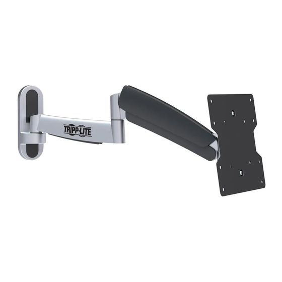
Owner's Manual
Flat Screen Wall Mount
CAUTION: DO NOT EXCEED MAXIMUM LISTED WEIGHT CAPACITY. SERIOUS INJURY OR
PROPERTY DAMAGE MAY OCCUR!
100x100
200x100
200x200
Este manual esta disponible en español en la página de Tripp Lite: tripplite.com
Ce manuel est disponible en français sur le site Web de Tripp Lite : tripplite.com
Русскоязычная версия настоящего руководства представлена на веб-сайте компании
Dieses Handbuch ist in deutscher Sprache auf der Tripp Lite-Website verfügbar: tripplite.com
1111 W. 35th Street, Chicago, IL 60609 USA • tripplite.com/support
Copyright © 2020 Tripp Lite. All rights reserved.
Full Motion
MODEL: DWM1742S
42"
MAX
Tripp Lite по адресу: tripplite.com
WARRANTY REGISTRATION
Register your product today and be
automatically entered to win an ISOBAR
surge protector in our monthly drawing!
tripplite.com/warranty
1
20 kg
20 kg
(44 lbs)
(44 lbs)
Advertisement

Related Manuals for Tripp Lite DWM1742S


Summary of Contents for Tripp Lite DWM1742S
- Page 1 (44 lbs) Este manual esta disponible en español en la página de Tripp Lite: tripplite.com Ce manuel est disponible en français sur le site Web de Tripp Lite : tripplite.com Русскоязычная версия настоящего руководства представлена на веб-сайте компании Tripp Lite по адресу: tripplite.com Dieses Handbuch ist in deutscher Sprache auf der Tripp Lite-Website verfügbar: tripplite.com...
- Page 2 NOTE: Read the entire instruction manual before you start installation and assembly. WARNING • Do not begin the installation until you have read and understood the instructions and warnings contained in this manual. If you have any questions regarding any of the instructions or warnings, please visit tripplite.com/support.
-
Page 3: Warranty & Warranty Registration
FREE Tripp Lite product!* * No purchase necessary. Void where prohibited. Some restrictions apply. See website for details. Tripp Lite has a policy of continuous improvement. Specifications are subject to change without notice. Photos and illustrations may differ slightly from actual products. -
Page 4: Component Checklist
Ensure that you have received all parts according to the component checklist prior to installing. If any parts are missing or faulty, visit www.tripplite.com/support for service. Wrench (x1) 4mm Hex Key (x1) 6mm Hex Key (x1) DWM1742S Nut (x1) M8 Hexagon Nut (x1) D8 Washer (x1) Package M... - Page 5 1. Separate VESA Plate from Wall Mount Wrench • Using the supplied wrench, loosen the two • Remove VESA plate upper knobs • Remove both lower knobs 2. Remove the Decorative Covers...
- Page 6 3a. Mount on Wood Stud Wall Find a wood stud location for mounting the wall mount Mark the exact location of the mounting holes Drill pilot holes Anchor Bolt Screw the wall mount onto the wall WARNING • Make sure that mounting screws are anchored into the center of the studs. Use of a stud finder is highly recommended.
- Page 7 3b. Mount on Solid Brick and Concrete Block Find and mark the exact location of mounting holes Drill pilot holes Concrete Anchor Anchor Bolt Screw the wall mount onto the wall WARNING • When installing wall mounts onto a concrete masonry unit (also known as a CMU or “cinder block”), verify that the actual concrete thickness is at least 35mm (1-3/8”) in order to hold the concrete anchors.
- Page 8 4. Install Decorative Covers D8 Washer M8 Hexagon Nut Wrench 5. Install VESA Plate Top of Display...
- Page 9 5. Install VESA Plate M4X14 / M5X14 M6X14 / M8X20 D5 Washer D8 Washer M8x20 M8x20 D8 Washer D8 Washer Small Spacer Small Spacer Small Spacer Note: Firmly secure the VESA plate to the display using the appropriate screws, washers and spacers (if necessary).
- Page 10 6. Hook the TV onto the Wall Mount Using an assistant or mechanical lifting equipment, lift the display with attached VESA plate. Set the VESA plate’s upper thumbscrews over the top flange of wall plate arm. Make sure the VESA plate’s lower screws fit inside of the wall plate arm’s lower hole.
-
Page 11: Tension Adjustment
7. Tension Adjustment 6mm Hex Tighten the socket screw if the arm assembly’s joints make popping sounds during adjustment. Keep the wall mount arm level during tension adjustment. You may need to slightly loosen or tighten the adjustment screw using the provided Hex Keys depending on the weight of display installed. If display settles on its own, rotate adjustment screw towards the “+”... - Page 12 9. Adjustment Hex Key 180° To correct the tilting angle, tighten the adjustment screws using the provided Hex Keys (or tighten the knob). +15° +3° -3° -15° 180° 180° Adjust to the desired location or tilt. Maintenance • Check that the bracket is secure and safe to use at regular intervals (at least every three months). •...