Advertisement
Quick Links
Owner's Manual
200x200/300x300
200x400/400x400
400x600
Este manual esta disponible en español en la página de Tripp Lite: tripplite.com
Ce manuel est disponible en français sur le site Web de Tripp Lite : tripplite.com
Русскоязычная версия настоящего руководства представлена на веб-сайте компании
Dieses Handbuch ist in deutscher Sprache auf der Tripp Lite-Website verfügbar: tripplite.com
WARRANTY REGISTRATION
Register your product today and be
automatically entered to win an ISOBAR
surge protector in our monthly drawing!
tripplite.com/warranty
1111 W. 35th Street, Chicago, IL 60609 USA • tripplite.com/support
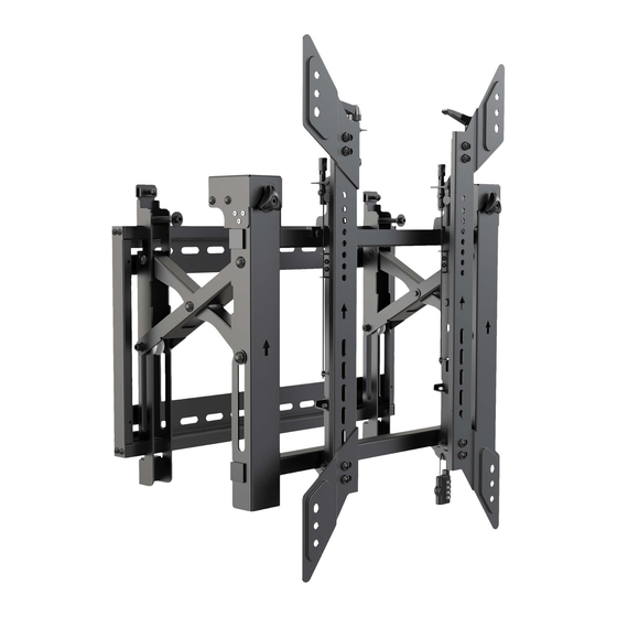
Video Wall
with Security
Model: DWMSCP4570VW
CAUTION: DO NOT EXCEED MAXIMUM LISTED WEIGHT CAPACITY. SERIOUS
INJURY OR PROPERTY DAMAGE MAY OCCUR!
70"
MAX
Tripp Lite по адресу: tripplite.com
®
Copyright © 2021 Tripp Lite. All rights reserved.
1
Portrait
154 lb.
154 lb.
(70 kg)
(70 kg)
RATED
RATED
Advertisement

Related Manuals for Tripp Lite DWMSCP4570VW


Summary of Contents for Tripp Lite DWMSCP4570VW
- Page 1 RATED Este manual esta disponible en español en la página de Tripp Lite: tripplite.com Ce manuel est disponible en français sur le site Web de Tripp Lite : tripplite.com Русскоязычная версия настоящего руководства представлена на веб-сайте компании Tripp Lite по адресу: tripplite.com Dieses Handbuch ist in deutscher Sprache auf der Tripp Lite-Website verfügbar: tripplite.com...
-
Page 2: Important Safety Instructions
PRODUCT REGISTRATION Visit tripplite.com/warranty today to register your new Tripp Lite product. You’ll be automatically entered into a drawing for a chance to win a FREE Tripp Lite product!* * No purchase necessary. Void where prohibited. Some restrictions apply. See website for details. -
Page 3: Component Checklist
Component Checklist IMPORTANT: Ensure you have received all parts according to the component checklist prior to installing. If any parts are missing or faulty, visit tripplite.com/support for service. Wall Plate (x1) Pop-Out Module (x1) Adapter Bracket (x2) VESA Adapter (x2) VESA Adapter (x2) Lock (x1) Package P... - Page 4 1. Solid Brick and Concrete Wall Mounting WARNING Installers must verify that the supporting surface will safely support the combined weight of the equipment and all attached hardware and components. 2.4” 95 mm 95 mm (60 mm) (3.7") (3.7") Ø 3/8” (Ø...
- Page 5 2. Video Wall Installation (mounting space as shown below) 3. Installing the Pop-Out Module Remove caps before installing the pop-out module.
- Page 6 3. Installing the Pop-Out Module Hang the pop-up module onto the wall plate. Secure it by tightening both screws. 4. Installing the Adapter Brackets For VESA hole patterns 400x400 or 600x400 Attach the VESA adapters to the adapter brackets using the appropriate screws and nuts so that the hole pattern can be expanded to VESA 400x400 or 600x400.
- Page 7 4. Installing the Adapter Brackets 4.1 For Flat-Back Screens...
- Page 8 4.2 For Bump-Out or Recessed-Back Screens M-D M-E M-D M-E Notes: • Choose the appropriate screws, washers and spacers (if necessary) according to the type of screen. • Position the adapter brackets as close as possible to the center of the display. •...
- Page 9 5. Hooking the Display onto the Pop-Out Module Notes: • Before Hooking the display, ensure the knobs are rotated to the unlock position. • Lift the display carefully and hook it onto the pop-out module. Rotate the knobs to the lock position to secure the display. •...
- Page 10 6. Adjustment Push the display left or right for fast alignment. Handles for tilt adjustment Screws for up-and-down micro-adjustments Knobs for in-and-out micro-adjustments...
- Page 11 6. Adjustment...
- Page 12 6. Adjustment...
- Page 13 6. Adjustment To pop out the display, push it inward and then release it. Kickstands provide tilt access for easy cable management and maintenance.
- Page 14 7. Level the Displays Adjust the display to keep it level in vertical and horizontal directions.
- Page 15 7. Level the Displays Note: Use the plastic locking piece to measure and keep a 1.2 mm gap between displays. Note: Install and adjust displays in the numerical order shown.
- Page 16 8. Fixing the Bracket Positions with the Anti-Skid Blocks Install both of the anti-skid blocks as close to the adapter brackets as possible. Tighten screws on the anti-skid blocks using a hex key to prevent the display from moving. 9. Lock the Pop-Out Module with the Plastic Locking Pieces Top View Side View 1111 W.