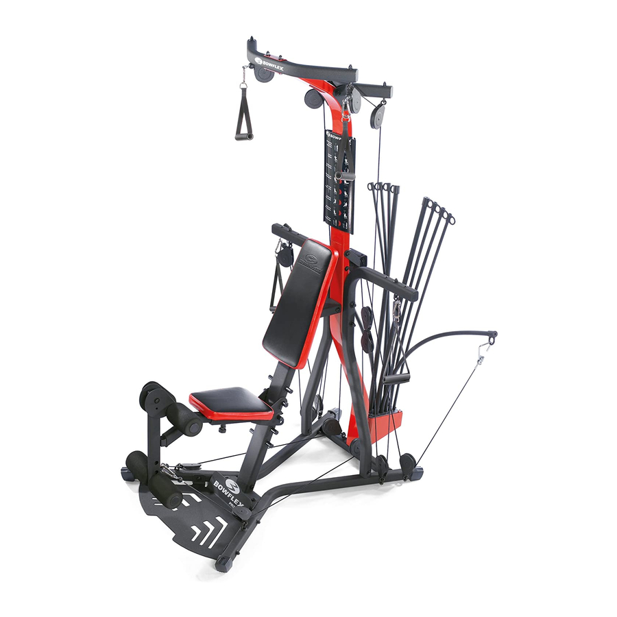
Bowflex PR3000 Assembly Manual
Bowflex home gym assembly manual
Hide thumbs
Also See for PR3000:
- Owner's manual (68 pages) ,
- Assembly manual (44 pages) ,
- Owner's manual (32 pages)

Related Manuals for Bowflex PR3000


Summary of Contents for Bowflex PR3000
-
Page 1: Assembly Manual
® ® PR3000 Home Gym Assembly Manual Nautilus Bowflex Schwinn Fitness StairMaster Universal Nautilus Institute ® ® ® ® ® ® 001-7279-063008A... -
Page 2: Table Of Contents
Before Assembly Select where you are going to locate your Bowflex® home gym carefully. The best location is on a hard, level surface. For best results, assemble your home gym in the location where you intend to use it. For safe operation, allow a workout area of at least 100”... -
Page 3: Important Safety Instructions
Important Safety Instructions This icon means a potentially hazardous situation which, if not avoided, could result in death or serious injury. Before using this equipment, obey the following warnings Read and understand all warnings on this machine. Carefully read and understand the Assembly Manual. •... -
Page 4: Hardware
(Hardware not actual size) Qty. 19 Qty. 2 Qty. 3 Qty. 4 Qty. 31 Qty. 3 Qty. 6 Qty. 4 Qty. 6 Hardware Qty. 6 Item #1 3/8”x 3/4” Hex Head Bolt Qty. 2 Item #2 5/16”x 2 1/2” Hex Head Bolt Qty. -
Page 5: Parts
Description Item # Qty. Base Platform Right Frame Rail Left Frame Rail Rear Cross Bar Central Support Lat Cross Bar with Pulleys Rear Lat Cross Bar Upper Lat Tower Right Pulley Arm Left Pulley Arm Rod Pack Lower Lat Tower Seat Back Seat Backbone Seat Bottom... -
Page 6: Assembly
Step 1: Assemble the Base Parts • Base Platform (#19) • Right Frame Rail (#20) • Left Frame Rail (#21) • Rear Cross Bar (#22) • Central Support (#23) Hardware • (4) 3/8” x 3/4” Hex Head Bolts (#1) • (4) 3/8”... -
Page 7: Attach The Rod Pack
Step 2: Attach the Rod Pack Parts • Rod Pack (#29) • Lower Lat Tower (#30) • Rod Pack Strap (#41) Hardware • (3) #10 x 1” Phillips Head Screws (#6) • (3) 1/4” Washers (#3) Tools • Phillips Head Screw Driver (not included) 2-1 Slide the Rod Pack into the Lower Lat Tower. -
Page 8: Attach The Lower Lat Assembly
Step 3: Attach the Lower Lat Assembly to the Base Assembly Parts • Competed Assembly (from step 1) • Lower Lat Tower Assembly (from step 2) Hardware • (2) 3/8” x 3/4” Hex Head Bolts (#1) • (2) 3/8” Washers (#5) Tools •... -
Page 9: Attach The Seat Support Rail
Step 4: Attach the Seat Support Rail Parts • Seat Support Rail (#34) • Completed Assembly (from step 3) Hardware • (4) 3/8” x 3/4” Hex Head Bolts (#1) • (4) 3/8” Washers (#5) Tools • Adjustable Wrench (not included) 4-1 Attach the Seat Support Rail to the Lower Lat Tower. -
Page 10: Attach Pulley Arms
Step 5: Attach the Pulley Arms Parts • Right Pulley Arm (#27) • Left Pulley Arm (#28) • Completed Assembly (from step 4) Hardware • (4) 3/8” x 3/4” Hex Head Bolts (#1) • (4) 3/8” Washers (#5) • (2) 1/2” x 9 1/2” Threaded Studs (#11) •... -
Page 11: Attach The Seat Bottom To The Seat Backbone
Step 6: Attach the Seat Bottom to the Seat Backbone Parts • Seat Bottom (#33) • Seat Backbone (#32) Hardware • (4) 5/16” x 3/4” Hex Head Bolts (#15) • (4) 5/16” Washers (#17) Tools • Adjustable Wrench (not included) 6-1 Attach the Seat Bottom to the Seat Backbone. -
Page 12: Attach Leg Extension Assembly
Step 7: Attach the Leg Extension Assembly Parts • Leg Extension Assembly (#37) • Leg Extension Lock Pin (#49) • Seat Bottom Assembly (from step 6) 7-1 Attach the Leg Extension Assembly to the Seat Bottom Assembly with the Leg Extension Lock Pin. Assembly Assembly Manual... -
Page 13: Attach Seat Back
Step 8: Attach the Seat Back Parts • Seat Back (#31) • Completed Assembly (from step 5) Hardware • (2) 5/16” x 2 1/2” Hex Head Bolts (#2) • (2) 5/16” Washers (#17) Tools • Adjustable Wrench (not included) 8-1 Attach the Seat back to the Seat Support Rail. 8-2 Install and tighten the hardware. -
Page 14: Attach The Lat Crossbar With Pulleys
Step 9: Attach the Lat Crossbar with Pulleys to the Upper Lat Tower Parts • Lat Crossbar with Pulleys (#24) • Upper Lat Tower (#26) Hardware • (2) 3/8” x 3” Hex Head Bolts (#13) • (4) 3/8” Washers (#5) •... -
Page 15: Attach The Rear Lat Cross Bar
Step 10: Attach the Rear Lat Cross Bar Parts • Rear Lat Cross Bar (#25) • Upper Lat Tower Assembly (from step 9) Hardware • (2) 1/2” x 5 1/4” Hex Head Bolts (#14) • (4) 1/2” Washers (#4) • (2) 1/2”... -
Page 16: Attach The Upper Lat Tower Assembly
Step 11: Attach the Upper Lat Tower Assembly to the Base Assembly Parts • Completed Assembly (from step 8) Hardware • (2) 3/8” x 3/4” Hex Head Bolts (#1) • (2) 3/8” Washers (#5) Tools • Adjustable Wrench (not included) 11-1 Attach the Upper Lat Tower Assembly to the Base Assembly. -
Page 17: Attach The Lat Pulley Housing
Step 12: Attach the Lat Pulley Housing Parts • Lat Pulley Housing (#36) • Completed Assembly (from step 11) Hardware • (3) 3/8” x 3/4” Hex Head Bolts (#1) • (3) 3/8” Washers (#5) Tools • Adjustable Wrench (not included) 12-1 Attach the Lat Pulley Housing to the Lat Tower. -
Page 18: Cable And Pulley Routing
Step 13: Cable and Pulley Routing the Rear Pulleys Parts • Completed Assembly (from step 12) Tools • Adjustable Wrench (not included) 13-1 Remove the 3/8” x 4 1/2” Hex Head Bolt and the 3/8” Washer in the center of the Lat Pulley Housing. 13-2 Remove the two pulley wheels from the Lat Pulley Housing. -
Page 19: Connect The Rod Cables
Assembly Step 14: Connect the Rod Cables through the Right Floating and Lat Tower Pulleys 14-1 Put the right cable that runs through the Lat Pulley Housing through the Floating Pulley (A). 14-2 Pull the same cable through the Pulley on the Rear Lat Cross Bar (B) and then through the Pulley on the Front Lat Cross Bar (C). -
Page 20: Connect The Right Cable
Assembly Step 15: Connect the Right Squat Cable through the Floating and Main Assembly Pulleys 15-1 Unwrap the Right Squat Cable from the Pulley on the front of the Base. 15-2 Put the cable under the cable shroud and under and through the Rear Cross Bar Pulley. Follow the arrows. 15-3 Put the cable down through the Inner Right Frame Rail Pulley and up through the Right Pulley Arm Pulley. -
Page 21: Leg Extension Cable Routing
Step 16: Leg Press Extension Cable Routing Parts • (3) Snap Hooks (#46) • (2) Leg Press Extension Cables (#45) 16-1 Attach one set of snap hooks onto the left and right squat cables. 16-2 Attach the Leg Press Extension Cables. 16-3 Attach a snap hook to the Leg Extension Assembly and connect the Leg Press Extension Cables. - Page 22 Assembly Manual...
-
Page 23: Contacts
UNITED STATES CUSTOMER SERVICE email customerservice@nautilus.com TECHNICAL/CUSTOMER SERVICE Tel: (800) NAUTILUS, (800-628-8458) Fax: (877) 686-6466 E-mail: cstech@nautilus.com CORPORATE HEADQUARTERS Nautilus, Inc. World Headquarters 16400 SE Nautilus Drive Vancouver, Washington, USA 98683 Phone: (800) NAUTILUS (800) 628-8458 Serial Number Date of Purchase Contacts INTERNATIONAL For technical assistance and a list of distributors in your area, please... - Page 24 Printed in China ©2008. Nautilus, Inc. All rights reserved. Nautilus, the Nautilus Logo, Universal, the Universal Logo, Bowflex, the Bowflex logo, Power Rod, StairMaster and Nautilus Institute are either regis- tered trademarks or trademarks of Nautilus, Inc. Schwinn is a registered trademark. All other trademarks are owned by their respective companies. Nautilus, Inc., World Headquarters, 16400 SE Nautilus Drive, Vancouver, WA 98683 1-800-NAUTILUS www.nautilus.com...