Table of Contents
Advertisement
Quick Links
Advertisement
Table of Contents

Related Manuals for Honeywell Notifier LCD6000N


Summary of Contents for Honeywell Notifier LCD6000N
- Page 1 LCD6000N Installation manual LCD Remote panel...
- Page 2 INDEX Detection system limits General description Installation Front panel controls User interface description Normal condition Events from zone in alarm condition Events from zone in fault condition PROGRAMMING MENU’ Address Password Buzzer volume LED Test LCD Test RS485 Serial connection Shield cable and earth connection Topographic LCD6000N board CN1 Terminal block...
- Page 3 NOTE: Do not try to install the LCD6000N without having read this manual. WARNING: This manual refers to all the features available in software revision indicated on manual’s cover. DETECTION SYSTEM LIMITS A security or fire detection system is useful for timely advice of each dangerous event, like fire, theft, intrusion and in some cases can provide automatic event management (evacuation messages diffusion, automatic extinguishing systems, CCTV plants interfacing, door and accesses lock, automatic warning of authorities etc.) but in any case, does not assure protection against property damage or resulting from fire or...
-
Page 4: National Regulations
National regulations This device must be installed and operate in compliance with these instructions and installing place local regulations. GENERAL DESCRIPTION DESCRIPTION LCD6000N is a LCD remote panel for the new series of AM-2000, AM-4000, AM-6000 control panels. A control panel can connect up to 12 or 16 LCD6000N as remote repeater panel according to the type of control panel. -
Page 5: Installation
INSTALLATION Dimensions for wall-mount The panel is designed to be wall- mounted through 4 self-blocking nogs (stone walls) or self-tapping screws (pre- built panels etc.) Screws diameter must be 5mm max. We advice not to install the panel near heating sources (radiators etc.) Plug-in the cable into CN1 Fix the incoming cable with a tie. -
Page 6: Front Panel Controls
FRONT PANEL CONTROLS SOUNDER ACKNOWLEDGMENT In alarm condition the following devices are active: - Control panel sounder output - Control module Type-ID HORN programmed - All control module activated by CBE association This button disable the following devices: - Control panel sounder output - Control module Type-ID HORN programmed enabled for tacitation. -
Page 7: User Interface Description
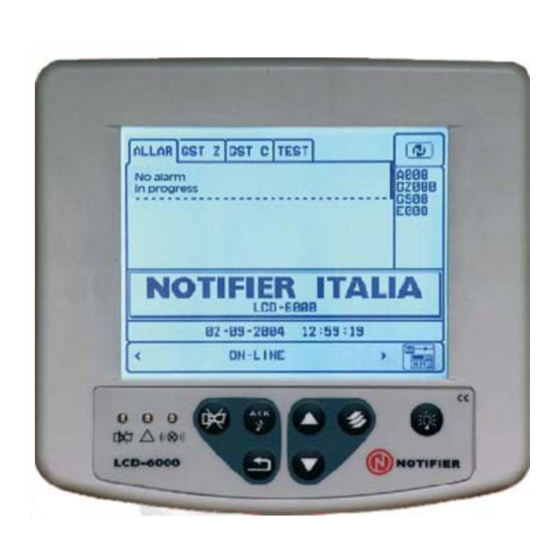
USER INTERFACE DESCRIPTION NORMAL CONDITION The following screen is displayed when the panel LCD6000 there are no fault conditions (alarm or fault): Panel icon status. In normal condition, without alarm and fault, the NOTIFIER trademark symbol is present. In the presence of points or zone not included an exclamation is displayed (!). In alarm condition the symbol Flame is displayed. - Page 8 The following screen is displayed when the control panel has a zone in alarm. Display area of the first event First zone alarm Counter zone in alarm Programmed text for the zone Date and time of the first event zone alarm Last alarm zone Date and time of...
- Page 9 The following screen is displayed when the control is in zone fault condition. Even the events of fault are initially displayed by zone. Date and time of the first Counter fault zone event of zone fault Date and time of the Display area of last event zone fault the first event...
-
Page 10: Programming Menu
PROGRAMMING MENU’ To enter in the initial configuration programming menu of the LCD6000N, hold the key for a wile. To change the panel configuration the 3A password level is required. To access the password level 3A press for a wile then the entering windows will displayed. With arrow keys select first number, than press to confirm. -
Page 11: Buzzer Volume
Password PASSWORD LEVEL 2 – For acknowledgement or reset LEVEL 2 password is required. After pressing the corresponding key the entering window for the password entry will displayed. With arrow keys select first number, than press to confirm. Repeat this step to enter the entire password. Default password is 22222. -
Page 12: Rs485 Serial Connection
RS485 Serial connection The connection of LDC6000N with the control panel use serial line RS485. RS-485 line must be installed in “MULTI-POINT” configuration (daisy chain). Each peripheral must be programmed with an address between 1 16. (refer to TAB.1). “Multi-Point”... - Page 13 Installation with separate power supply +24V GND +24V GND Connect two wires to the RS485 EOL= 120 control panel terminal block (LIN+ EOL= 120 and LIN- ) to the corresponding terminals of the first device on the line. Continue wiring from the first device to the next, and so on.
- Page 14 Topographic LDC6000N board CN1 Terminal block Buzzer CNT terminal block for front keypad Cables specifications Up to 1.200 mt. 18 AWG Belden 9574 type Up to 1.500 mt. 16 AWG Belden 9575 type PAGE - 12 Installation Manual LCD6000N NOTIFIER ITALIA Doc.
- Page 15 CN1 Terminal block Terminal N° Description Note block LIN – RS 485 Serial line Negative reference for serial line RS 485* RS 485 Serial line LIN + Power input + 24Vdc * TO BE USED IN CASE OF POWER NOT COMMON WITH THE CONTROL PANEL. ENVIRONMENTAL FEATURES Operative temperature: - 5°C ÷...
- Page 16 E-mail: notifier@notifier.it A Honeywell company Every care has been taken in the preparation of this data sheet but no liability can be accepted for the use of the information therein. Design features may be changed or amended without prior notice.