
Related Manuals for Raymarine M81138


Summary of Contents for Raymarine M81138
- Page 1 All manuals and user guides at all-guides.com Distributed by Any reference to Raytheon or RTN in this manual should be interpreted as Raymarine. The names Raytheon and RTN are owned by the Raytheon Company.
- Page 2 All manuals and user guides at all-guides.com I/O Drive Installation Guide Drives covered: M81138 I/O (Stern) Drive 12 V E12019 KAD 32 I/O (Stern) Drive 12 V Document number: 81176-3 March 2001...
-
Page 3: Safety Notices
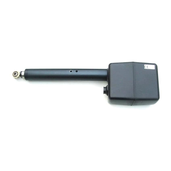
EMC conformance All Raymarine equipment and accessories are designed to the best industry standards for use in the recreational marine environment. The design and manufacture of Raymarine equipment and... - Page 4 I/O Drive - Installation Guide Introduction Product description Welcome to the installation guide for the Raymarine inboard/ outboard drive (also known as an I/O or stern drive). This product is intended to operate the boat’s steering mechanism as part of a Raymarine autopilot system.
-
Page 5: Drive Specifications
All manuals and user guides at all-guides.com I/O Drive - Installation Guide Specifications Drive specifications Table 1: Drive specifications I/O drive Performance M81138 (12 V) (at nominal voltage) E12019 (KAD 32: 12 V) Drive method Electromechanical Maximum thrust 150 kg (330 lb) Maximum stroke 214 mm (8.3 in) -
Page 6: Installation Instructions
Complete the post-installation checks. page 20 1. EMC installation guidelines All Raymarine equipment and accessories are designed to the best industry standards for use in the recreational marine environment. Their design and manufacture conforms to the appropriate Electromagnetic Compatibility (EMC) standards, but correct installation is required to ensure that performance is not compromised. -
Page 7: Suppression Ferrites
Raymarine equipment. Always use the ferrites supplied by Raymarine. Connections to other equipment If your Raymarine equipment is to be connected to other equipment using a cable not supplied by Raymarine, a suppression ferrite MUST always be attached to the cable near to the Raymarine unit. -
Page 8: Mounting The Drive
Using a suitable thread-locking compound on the threads will help keep the bolts securely tightened. Raymarine provide installation kits (see Figure 4) so you can fit the drive unit to stern drive systems made by: • Volvo: see page 8 for installation instructions •... - Page 9 All manuals and user guides at all-guides.com I/O Drive - Installation Guide Installation for Volvo (after type 872215) 1. Fit the girdle support bracket (supplied in the installation kit) as shown in Figure 5: • remove the locating pin that attaches the cable rod to the tiller end block •...
- Page 10 All manuals and user guides at all-guides.com I/O Drive - Installation Guide Adaptor pin bracket Cable end sheath Cable end sheath shoulder D3367-2 Figure 6: Fitting the adaptor pin bracket (Volvo) 3. Fit the I/O drive into the girdle support bracket (see Figure 7): •...
- Page 11 All manuals and user guides at all-guides.com I/O Drive - Installation Guide 5. Complete a hardover to hardover check: • Slowly turn the steering system from hardover to hardover. • Make sure that the drive unit and adaptor pin bracket do not come into contact with any part of the engine, boat or steering system.This includes any engine hoses that may have a passing contact with the I/O drive unit.
- Page 12 All manuals and user guides at all-guides.com I/O Drive - Installation Guide • make sure that the bracket is vertical and that the securing bolts are on the bow (forward) side of the cable end sheath • tighten the two securing bolts on the adaptor pin bracket 165 mm (6.5 in) Cable end sheath...
- Page 13 Before you install any of the autopilot components, make sure there is sufficient space between the complete drive unit and the engine manifold. Use Raymarine installation kit D309 to install the I/O drive unit to Mercruiser engines manufactured from 1994 onwards. Install the I/O drive by following these steps: 1.
- Page 14 All manuals and user guides at all-guides.com I/O Drive - Installation Guide Retaining pins Pivot assembly Tiller arm Twin engine connecting bar Power steering ram D5180-1 Figure 11:Fitting the pivot assembly (Mercruiser 95) 3. Fit the main support bracket to the spool valve cable connection on the steering system (see Figure 12): •...
- Page 15 All manuals and user guides at all-guides.com I/O Drive - Installation Guide 4. Place the I/O drive’s pushrod end on the pivot assembly pin – the flat part of the pushrod should rest on top of the pivot assembly. 5. Fit the R-clip to the pivot assembly pin to secure the I/O drive pushrod in place.
- Page 16 All manuals and user guides at all-guides.com I/O Drive - Installation Guide Installation for Volvo KAD 32 Note: You must use the KAD 32 I/O drive unit (part number E12019) for this system. Volvo adaptor pin Extension bracket Securing bolt (x2) Shakeproof washer (x2) Girdle support...
- Page 17 All manuals and user guides at all-guides.com I/O Drive - Installation Guide Filter assembly bolts Filter assembly Flexible hose Extension bracket bolts KAD 32 bracket bolt Extension bracket KAD 32 bracket KAD 32 bracket bolt D5216-1 Figure 14:Fitting the extension bracket When you have fitted the extension bracket: 1.
- Page 18 All manuals and user guides at all-guides.com I/O Drive - Installation Guide Volvo adaptor pin Split pin Tiller end block D5213-1 Figure 15:Fitting the Volvo adaptor pin 3. Fit the girdle support bracket onto the spool valve rod: • the adaptor pin bracket must sit against, but not on, the shoulder on the spool valve rod •...
- Page 19 All manuals and user guides at all-guides.com I/O Drive - Installation Guide I/O drive girdle tube Pushrod end Girdle support bracket D5215-1 Figure 17:Fitting the I/O drive unit (KAD 32) CAUTION: The fixed and spring-loaded location pins must be fully engaged in the I/O drive girdle tube.
-
Page 20: Electrical Connections
All manuals and user guides at all-guides.com I/O Drive - Installation Guide 4. Rotate the main body as required. Fixing screw Front cover Lock nut D5183-1 Figure 18:Rotating the main body of the I/O drive unit 5. Tighten the lock nut, making sure it is less than one turn from the start of the thread. -
Page 21: Post-Installation Check
All manuals and user guides at all-guides.com I/O Drive - Installation Guide 4. Secure the cable close to the I/O drive unit, making sure there is enough free length to allow the drive unit to move. 5. Complete another hardover check: use the steering wheel to move the rudder from hardover to hardover, and check that the cable does not catch on any part of the boat or its fittings. -
Page 22: Maintenance
• check drive alignment • check cables for signs of wear or damage EMC servicing and safety guidelines • Raymarine equipment should be serviced only by authorized Raymarine service technicians. They will ensure that service procedures and replacement parts used will not affect performance. -
Page 23: Product Support
Authorized Service Representatives. If you encounter any difficulties with this product, please contact either your national distributor, or your service representative, or the Raymarine Technical Services Call Center. Refer to the back cover or the Worldwide Distributor List for contact details. Raymarine Ltd...