Table of Contents
Advertisement
Quick Links
TABLE OF CONTENTS
1 Safety Precautions----------------------------------------------- 3
1.1. General Guidelines---------------------------------------- 3
1.2. Before Repair and Adjustment ------------------------- 4
1.3. Caution For Fuse Replacement------------------------ 4
1.4. Protection Circuitry ---------------------------------------- 4
1.5. Safety Part Information----------------------------------- 4
2 Warning -------------------------------------------------------------- 5
to Electrostatically Sensitive (ES) Devices---------- 5
2.2. Precaution of Laser Diode------------------------------- 6
2.4. Handling Precaution for Traverse Unit --------------- 8
3 Service Navigation ----------------------------------------------- 9
3.1. Service Information --------------------------------------- 9
4 Specifications ----------------------------------------------------10
5 Location of Controls and Components ------------------ 11
Model No.
Product Color: (K)...Black Type
PAGE
Operations ------------------------------------------------- 11
5.2. Connections ----------------------------------------------- 12
5.3. Disc operations ------------------------------------------- 13
5.4. Notes on CD-R and CD-RW -------------------------- 14
5.5. External unit (iPod or iPhone)------------------------- 14
6 Operating Instructions ---------------------------------------- 15
6.1. CD Door Ass'y Jam-------------------------------------- 15
7 Self Diagnostic and Doctor Mode Setting -------------- 17
7.1. Self Diagnostic Mode ----------------------------------- 17
7.2. Self Diagnostic Function Error Code ---------------- 18
7.3. Entering Doctor Mode----------------------------------- 19
7.4. Sales Demonstration Lock Function Mode -------- 22
8 Service Fixture & Tools --------------------------------------- 23
9 Disassembly and Assembly Instructions--------------- 24
9.1. Disassembly flow chart --------------------------------- 25
9.2. Types of Screws------------------------------------------ 26
© Panasonic Corporation 2010. All rights reserved.
Unauthorized copying and distribution is a violation of
law.
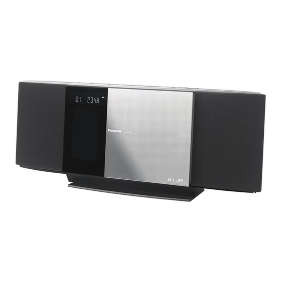
Compact Stereo System
SC-HC30EF
SC-HC30EG
(S)...Silver Type
(P)...Pink Type (SC-HC30EG only)
PSG1002012CE
PAGE
Advertisement
Table of Contents

Related Manuals for Panasonic SC-HC30EF


Summary of Contents for Panasonic SC-HC30EF
-
Page 1: Table Of Contents
9 Disassembly and Assembly Instructions--------------- 24 5 Location of Controls and Components ------------------ 11 9.1. Disassembly flow chart --------------------------------- 25 9.2. Types of Screws------------------------------------------ 26 © Panasonic Corporation 2010. All rights reserved. Unauthorized copying and distribution is a violation of law. - Page 2 9.3. Main Parts Location Diagram ------------------------- 26 14.1. SERVO/SYSTEM CONTROL BLOCK 9.4. Disassembly of Stand Unit ----------------------------- 27 DIAGRAM ------------------------------------------------- 79 9.5. Replacement of CD Door Ass’y ---------------------- 27 14.2. AUDIO BLOCK DIAGRAM ---------------------------- 80 9.6. Disassembly of Net Frame Assembly--------------- 29 14.3.
-
Page 3: Safety Precautions
1 Safety Precautions 1.1. General Guidelines 1. When servicing, observe the original lead dress. If a short circuit is found, replace all parts which have been overheated or damaged by the short circuit. 2. After servicing, see to it that all the protective devices such as insulation barriers, insulation papers shields are properly installed. -
Page 4: Before Repair And Adjustment
1.2. Before Repair and Adjustment Disconnect AC power, discharge unit AC Capacitors as such C5700, C5701, C5702, C5706, C5708 and C5709 through a 10W, 1W resistor to ground. Caution : DO NOT SHORT-CIRCUIT DIRECTLY (with a screwdriver blade, for instance), as this may destroy solid state devices. After repairs are completed, restore power gradually using a variac, to avoid overcurrent. -
Page 5: Warning
2 Warning 2.1. Prevention of Electro Static Discharge (ESD) to Electrostatically Sensi- tive (ES) Devices Some semiconductor (solid state) devices can be damaged easily by static electricity. Such components commonly are called Elec- trostatically Sensitive (ES) Devices. Examples of typical ES devices are integrated circuits and some field-effect transistors and semiconductor “chip”... -
Page 6: Precaution Of Laser Diode
2.2. Precaution of Laser Diode CAUTION! THIS PRODUCT UTILIZES A LASER. USE OF CONTROLS OR ADJUSTMENTS OR PERFORMANCE OF PROCEDURES OTHER THAN THOSE SPECIFIED HEREIN MAY RESULT IN HAZARDOUS RADIATION EXPOSURE. Caution: This product utilizes a laser diode with the unit turned "on", invisible laser radiation is emitted from the pickup lens. Wavelength: 795 nm (CD) Maximum output radiation power from pickup: 100 μW/VDE Laser radiation from the pickup unit is safety level, but be sure the followings:... -
Page 7: Service Caution Based On Legal Restrictions
2.3. Service caution based on Legal restrictions 2.3.1. General description about Lead Free Solder (PbF) The lead free solder has been used in the mounting process of all electrical components on the printed circuit boards used for this equipment in considering the globally environmental conservation. The normal solder is the alloy of tin (Sn) and lead (Pb). -
Page 8: Handling Precaution For Traverse Unit
2.4. Handling Precaution for Traverse Unit The laser diode in the optical pickup unit may break down due to static electricity of clothes or human body. Special care must be taken avoid caution to electrostatic breakdown when servicing and handling the laser diode in the traverse unit. Cautions to Be Taken in Handling the Optical Pickup Unit 2.4.1. -
Page 9: Service Navigation
3 Service Navigation 3.1. Service Information This service manual contains technical information which will allow service personnel’s to understand and service this model. Please place orders using the parts list and not the drawing reference numbers. If the circuit is changed or modified, this information will be followed by supplement service manual to be filed with original service manual. -
Page 10: Specifications
4 Specifications I Amplifier Section RMS Output Power Stereo Mode 20 W per channel (6 Ω), 1 kHz, Front Ch (both ch driven) 10 % THD Total RMS Stereo mode power 40 W Phone jack Terminal Stereo, 3.5 mm (1/8”) jack max. -
Page 11: Location Of Controls And Components
5 Location of Controls and Components 5.1. Main Unit & Remote Control Key Button Operations... -
Page 12: Connections
5.2. Connections... -
Page 13: Disc Operations
5.3. Disc operations... -
Page 14: Notes On Cd-R And Cd-Rw
5.4. Notes on CD-R and CD-RW 5.5. External unit (iPod or iPhone) -
Page 15: Operating Instructions
6 Operating Instructions 6.1. CD Door Ass’y Jam 6.1.1. Removing the CD Step 2 : Gently push the CD Door Ass’y as arrow shown until the CD is fully in sight. Step 1 : Insert a flathead screwdriver into the hole behind the Step 3 : Remove the CD. - Page 16 6.1.2. Removing the iPod Step 2 : Gently push the CD Door Ass’y as arrow shown until the iPod is fully in sight. Step 1 : Insert a flathead screwdriver into the hole behind the Step 3 : Remove the iPod. CD Door Ass’y and push the Cam Gear from point B to A.
-
Page 17: Self Diagnostic And Doctor Mode Setting
7 Self Diagnostic and Doctor Mode Setting This unit is equipped with features of self diagnostic & doctor mode setting for checking the functions & reliability. 7.1. Self Diagnostic Mode Here is the procedures to enter into Self Diagnostic Mode. Step 1 : Turn on the unit, and then press and hold [I] button for 2 seconds follow by [ ] on the unit. -
Page 18: Self Diagnostic Function Error Code
7.2. Self Diagnostic Function Error Code 7.2.1. CD Mechanism Error Code Table Error Code Diagnostic Contents Description of error Automatic FL Display Remarks CD H15 CD Open Abnormal During operation Press [ ] on main unit for POS_SW_R On fail to be next error. -
Page 19: Entering Doctor Mode
7.3. Entering Doctor Mode Here is the procedures to enter into Doctor Mode. Step 1 : Turn on the unit, and then pressing and holding [I] on main unit in order while press [4] and [7] on the remote control. Step 2 : The display show as follow. - Page 20 7.3.2. Doctor Mode Table 2 Item Key Operation FL Display Mode Name Description Front Key FL Display Test To check the FL segments In Doctor Mode: display (All segments will 1. Press [1] button on remote con- light up) trol. To cancel, press [0] button on remote control.
- Page 21 7.3.3. Doctor Mode Table 3 Item FL Display Key Operation Mode Name Description Front Key Cold Start To activate cold start upon In Doctor Mode: next AC power up. 1. Press [SLEEP] button on remote control. To exit Doctor Mode, press button The [NO DISC] display will appear after 3s, on main unit or remote control.
-
Page 22: Sales Demonstration Lock Function Mode
7.4. Sales Demonstration Lock Function Mode 7.4.1. Setting Here is the procedures to enter into Sales Demonstration Lock. Step 1 : Turn on the unit. Step 2 : Select to iPod mode. Step 3 : Press and hold [ ] button follow by [ ] button on the unit for 5 sec. -
Page 23: Service Fixture & Tools
8 Service Fixture & Tools Prepare service tools before process service position. Service Tools Remarks CD Servo P.C.B. (CN7002) - Vertical Main P.C.B. (CN7002) RFKZHC30K1 (25P FFC) Panel P.C.B. (CN6801) - Vertical Main P.C.B. (CN900) RFKZHC30K2 (25P FFC) -
Page 24: Disassembly And Assembly Instructions
9 Disassembly and Assembly Instructions Caution Note: • This section describes the disassembly and/or assembly procedures for all major printed circuit boards & main compo- nents for the unit. (You may refer to the section of “Main components and P.C.B Locations” as described in the service manual) •... -
Page 25: Disassembly Flow Chart
9.1. Disassembly flow chart The following chart is the procedure for disassembling the casing and inside parts for internal inspection when carrying out the ser- vicing. To assemble the unit, reverse the steps shown in the chart below. -
Page 26: Types Of Screws
9.2. Types of Screws 9.3. Main Parts Location Diagram... -
Page 27: Disassembly Of Stand Unit
9.4. Disassembly of Stand Unit 9.5. Replacement of CD Door Ass’y 9.5.1. Disassembly of CD Door Ass’y Step 1 : Remove 2 screws. Step 2 : Lift up to remove the Stand Unit. Step 1 : Insert a flathead screwdriver into the hole behind the CD Door Ass’y and push the Cam Gear from point A to B. - Page 28 Step 2 : Gently push the CD Door Ass’y manually until it is fully 9.5.2. Assembly of CD Door Ass’y extended. Step 1 : Turn the Cam Gear as diagram shown. Step 3 : Lift up the CD Door Ass’y slightly as arrow shown and push it as arrow shown.
-
Page 29: Disassembly Of Net Frame Assembly
Step 2 : Align the CD Door Ass’y with the (upper & lower rib), 9.6. Disassembly Frame with guide reel (A & B) on the front panel. Assembly Step 3 : Gently slide the CD Door Ass’y until it is fully closed. Caution : Do not exert strong force to slide the CD Door 9.6.1. - Page 30 Caution : During assembling, ensure that the bosses are 9.6.2. Disassembly of Net Frame Assem- aligned to their respective holes in Front Speaker Assem- bly (R) bly (L) as shown. Step 1 : Gently lift up Net Frame Assembly (R). Caution : During assembling, ensure the net frame assem- bly (R) is seated properly Step 2 : Remove Net Frame Assembly (R) as arrow shown.
-
Page 31: Disassembly Of Front Panel Block
Caution : During assembling, ensure that the bosses are 9.7. Disassembly of Front Panel aligned to their respective holes in Front Speaker Assem- Block bly (R) as shown. • Refer to “Disassembly of Stand Unit”. • Refer to “Disassembly of CD Door Ass’y”. •... -
Page 32: Disassembly Of Top Ornament Unit
Step 3 : Slightly lift up the Front Panel Block. 9.8. Disassembly of Top Ornament Unit • Refer to “Disassembly of Stand Unit”. • Refer to “Disassembly of CD Door Ass’y”. • Refer to “Disassembly of Net Frame Assembly”. • Refer to “Disassembly of Front Panel Block”. Step 1 : Remove 4 screws. -
Page 33: Disassembly Of Button P.c.b
9.9. Disassembly of Button P.C.B. 9.10. Disassembly of Passive Radia- • Refer to “Disassembly of Top Ornament Unit”. tor (SP5). • Refer to “Disassembly of Net Frame Assembly (L)”. Step 1 : Remove 5 screws. Step 1 : Remove 4 screws. Step 2 : Remove Passive Raidator (SP5). -
Page 34: Disassembly Of Passive Radiator (Sp6)
9.11. Disassembly of Passive Radia- 9.12. Disassembly of Front Speaker tor (SP6). (SP1). • Refer to “Disassembly of Net Frame Assembly (R)”. • Refer to “Disassembly of Stand Unit”. • Refer to “Disassembly of CD Door Ass’y”. Step 1 : Remove 4 screws. •... - Page 35 Step 3 : Lift up the Front Speaker Assembly (L). Caution 1 : During assembling, of the Front Speaker (SP1), insert the speaker wires into the hole in the Front Speaker Assembly (L). Caution 2 : Ensure that the Front Speaker (SP1) soldering terminals face the Passive Radiator.
-
Page 36: Disassembly Of Front Speaker (Sp2)
9.13. Disassembly of Front Speaker Step 3 : Remove 4 screws. Step 4 : Lift up the Front Speaker (SP2). (SP2). • Refer to “Disassembly of Stand Unit”. • Refer to “Disassembly of CD Door Ass’y”. • Refer to “Disassembly of Net Frame Assembly”. •... -
Page 37: Disassembly Of Passive Radiator (Sp3)
9.14. Disassembly of Passive Radia- tor (SP3). • Refer to “Disassembly of Stand Unit”. • Refer to “Disassembly of CD Door Unit”. • Refer to “Disassembly of Net Frame Assembly”. • Refer to “Disassembly of Front Panel Block”. • Refer to “Disassembly of Top Ornament Unit”. •... -
Page 38: Disassembly Of Passive Radiator (Sp4)
9.15. Disassembly of Passive Radia- 9.16. Disassembly of Traverse Unit. tor (SP4). • Refer to “Disassembly of Stand Unit”. • Refer to “Disassembly of CD Door Unit”. • Refer to “Disassembly of Stand Unit”. • Refer to “Disassembly of Net Frame Assembly”. •... -
Page 39: Disassembly Of Traverse Cover & Traverse Ass'y
9.17. Disassembly of Traverse Cover Step 5 : Lift up the Traverse Ass’y to remove it. & Traverse Ass’y. • Refer to “Disassembly of Traverse Unit”. Step 1 : Release 3 catches. Step 2 : Remove the Traverse Cover. Step 3 : Detach 25P FFC at the connector (CN7002) on the CD Servo P.C.B.. -
Page 40: Disassembly Of Cd Servo P.c.b
9.18. Disassembly Servo 9.19. Disassembly Headphone/ P.C.B. AUX P.C.B. • Refer to "Disassembly of Traverse Unit” • Refer to “Disassembly of Stand Unit”. • Refer to “Disassembly of CD Door Unit”. Step 1 : Desolder the terminal. • Refer to “Disassembly of Net Frame Assembly”. Step 2 : Remove 3 screws. -
Page 41: Disassembly Of Pcb Block
9.20. Disassembly of PCB Block • Refer to “Disassembly of Stand Unit”. • Refer to “Disassembly of CD Door Unit”. • Refer to “Disassembly of Net Frame Assembly”. • Refer to “Disassembly of Front Panel Block”. • Refer to "Disassembly of Traverse Unit” •... - Page 42 Step 7 : Remove 2 screws. Caution : During assembling, ensure the PCB Block is seated properly on the locator and catch. Step 8 : Remove 4 screws. Step 9 : Release the catch on the Vertical Main P.C.B. Step 10 : Remove PCB Block.
-
Page 43: Disassembly Of Smps P.c.b
9.21. Disassembly of SMPS P.C.B. Caution : During assembling, ensure the Horizontal Main P.C.B. is seated properly on the locator. • Refer to “Disassembly of PCB Block”. Step 1 : Remove 3 screws. Step 2 : Detach 11P cable at the connector (CN100) on the Horizontal Main P.C.B.. -
Page 44: Replacement Of Switching Regulator Ic (Ic5701)
Step 6 : Remove 4 screws. 9.22. Replacement of Switching Reg- Step 7 : Remove SMPS P.C.B. as arrow shown. ulator IC (IC5701) • Refer to "Disassembly of SMPS P.C.B.". 9.22.1. Disassembly of Switching Regula- tor IC (IC5701) Caution : Handle the heatsink unit and P.C.B. with caution due to its high temperature after prolonged use. - Page 45 Step 4 : Remove 1 screw. Step 3 : Mount the Switching Regulator IC (IC5701) onto Step 5 : Remove the Switching Regulator IC (IC5701). SMPS P.C.B. Caution : Ensure the Switching Regulator IC (IC5701) is seated properly on the SMPS P.C.B.. 9.22.2.
-
Page 46: Replacement Of Voltage Regulator Ic (Ic2910)
9.23. Replacement of Voltage Regu- Step 4 : Remove 1 screw. Step 5 : Remove the Voltage Regulator IC (IC2910). lator IC (IC2910) • Refer to "Disassembly of SMPS P.C.B.". 9.23.1. Disassembly of Voltage Regulator IC (IC2910) Caution : Handle the heatsink unit and P.C.B. with caution due to its high temperature after prolonged use. -
Page 47: Replacement Of Diode (D5802)
Step 3 : Mount the Voltage Regulator IC (IC2910) onto SMPS 9.24. Replacement of Diode (D5802) P.C.B. • Refer to "Disassembly of SMPS P.C.B.". Caution : Ensure the Voltage Regulator IC (IC2910) is seated properly on the SMPS P.C.B.. 9.24.1. Disassembly of Diode (D5802) Caution : Handle the heatsink unit and P.C.B. -
Page 48: Disassembly Of Horizontal Main P.c.b. And Vertical Main P.c.b
9.24.2. Assembly of Diode (D5802) 9.25. Disassembly Horizontal Step 1 : Apply grease to the Heatsink Unit. Main P.C.B. and Vertical Main Step 2 : Mount the Diode (D5802) onto SMPS P.C.B. P.C.B. Caution : Ensure the Diode (D5802) is seated properly on the SMPS P.C.B.. -
Page 49: Replacement Of Power Amplifier Ic (Ic1)
9.26. Replacement of Power Ampli- Step 3 : Desolder pins of Power Amplifier IC (IC1) on the Verti- cal Main P.C.B. (Side B). fier IC (IC1) Step 4 : Remove the Power Amplifier IC (IC1). • Refer to "Disassembly of Horizontal Main P.C.B. and Vertical Main P.C.B.". -
Page 50: Disassembly Of Tuner P.c.b
Step 3 : Apply grease onto the top side of the Power Amplifier 9.27. Disassembly of Tuner P.C.B. IC (IC1). • Refer to “Disassembly of Stand Unit”. Step 4 : Fix the Heatsink Unit onto the Vertical Main P.C.B.. • Refer to “Disassembly of CD Door Ass’y”. •... -
Page 51: Disassembly Of Fan Unit
Caution : During assembling, ensure the Tuner P.C.B. is 9.28. Disassembly of Fan Unit seated properly on the locator. • Refer to “Disassembly of Stand Unit”. • Refer to “Disassembly of CD Door Ass’y”. • Refer to “Disassembly of Net Frame Assembly”. •... -
Page 52: Disassembly Of Panel P.c.b
Caution : During assembling, ensure that the wires are 9.29. Disassembly of Panel P.C.B. pushed into the groove and dressed porperly as shown in • Refer to “Disassembly of Stand Unit”. the diagram below. • Refer to “Disassembly of CD Door Ass’y”. •... -
Page 53: Disassembly Of Ir P.c.b. And Ipod/Iphone Switch P.c.b
Step 3 : Lift up the Panel P.C.B.. 9.30. Disassembly of IR P.C.B. and Step 4 : Detach 7P wires at the connector (P6803) on the iPod/iPhone Switch P.C.B. Panel P.C.B.. • Refer to “Disassembly of Stand Unit”. • Refer to “Disassembly of CD Door Ass’y”. •... - Page 54 Caution : During assembling, ensure the IR P.C.B. is seated Step 5 : Upset the IR P.C.B.. properly on the locator. Step 6 : Detach 10P FFC at the connector (CN300) on the IR P.C.B.. Step 7 : Remove the IR P.C.B. and iPod/iPhone Switch P.C.B..
-
Page 55: Disassembly Of Motor P.c.b., Door Switch P.c.b. And Interlock Switch P.c.b
9.31. Disassembly of Motor P.C.B., Step 3 : Release 1 catch. Step 4 : Lift up Door Switch P.C.B.. Door Switch P.C.B. and Inter- lock Switch P.C.B. • Refer to “Disassembly of Stand Unit”. • Refer to “Disassembly of CD Door Ass’y”. •... - Page 56 Step 5 : Remove 2 screw. Step 9 : Desolder 2P on Motor P.C.B.. Step 6 : Release 1 catch. Step 10 : Remove the Motor P.C.B., Door Switch P.C.B. and Interlock Switch P.C.B. altogether. Step 7 : Slightly rotate Interlock Switch P.C.B.. Step 8 : Lift up Interlock Switch P.C.B.
-
Page 57: Disassembly Of Motor Assembly
9.32. Disassembly of Motor Assem- Step 4 : Remove the Belt Pully. • Refer to “Disassembly of Stand Unit”. • Refer to “Disassembly of CD Door Ass’y”. • Refer to “Disassembly of Net Frame Assembly”. • Refer to “Disassembly of Front Panel Block”. •... -
Page 58: Disassembly Of Ipod/Iphone P.c.b
Step 6 : Remove 2 screws. 9.33. Disassembly of iPod/iPhone Step 7 : Remove the Motor. P.C.B. • Refer to “Disassembly of Stand Unit”. • Refer to “Disassembly of CD Door Ass’y”. • Refer to “Disassembly of Net Frame Assembly”. •... - Page 59 Step 2 : Release catch to remove push lever. Step 4 : Press & lift up the Docking Holder. Caution : Do not excert strong force to the Push Lever dur- ing removal and assembly. Step 5 : Remove the Docking Holder. Step 3 : Remove 2 screws.
- Page 60 Step 6 : Remove the iPod Docking Tub Assembly. Step 8 : Release the 2 catches on the iPod Docking Tub Assembly. Caution : During assembling, ensure the catches are prop- erly fixed. Step 9 : Remove the Docking Tub. Step 7 : Remove 2 screws.
- Page 61 Step 10 : Remove the iPod/iPhone P.C.B. as arrow shown. Step 2 : Align the docking holder to the 2 bosses on the front panel block. Step 3 : Fit the docking holder firmly onto the front panel block 9.33.1. Assembly of Docking Holder by pressing as arrow shown.
-
Page 62: Service Position
10 Service Position Note: For description of the disassembly procedures, see the Section 9 10.1. Checking & Repairing of Panel 10.2. Checking & Repairing of CD P.C.B. Servo P.C.B. Step 1 : Remove the Stand Unit. Step 1 : Remove the Stand Unit. Step 2 : Remove the CD Door Ass’y. -
Page 63: Checking & Repairing Of Smps P.c.b
Step 9 : Connect 25P extension cable (RFKZHC30K1) from 10.3. Checking & Repairing of SMPS CN7002 on the CD Servo P.C.B. to CN7002 on the Vertical P.C.B. Main P.C.B.. Step 10 : Check and repair the CD Servo P.C.B. according to the diagram shown. - Page 64 Step 13 : Connect 2P wire at the connector (CN103) on the Step 15 : Connect 25P extension cable (RFKZHC30K1) from Horizontal Main P.C.B.. CN7002 on the CD Servo P.C.B. to CN7002 on the Vertical Main P.C.B.. Step 14 : Connect 25P extension cable (RFKZHC30K2) from CN6801 on the Panel P.C.B.
-
Page 65: Checking & Repairing Of Horizontal Main P.c.b
10.4. Checking & Repairing of Hori- Step 13 : Connect 7P FFC at the connector (CN902) on the Vertical Main P.C.B.. zontal Main P.C.B. Step 1 : Remove the Stand Unit. Step 2 : Remove the CD Door Ass’y. Step 3 : Remove the Net Frame Assembly. Step 4 : Remove the Front Panel Block. -
Page 66: Checking & Repairing Of Vertical Main P.c.b. (Side A)
Step 16 : Connect 25P extension cable (RFKZHC30K1) from 10.5. Checking & Repairing of Verti- CN7002 on the CD Servo P.C.B. to CN7002 on the Vertical cal Main P.C.B. (Side A) Main P.C.B.. Step 1 : Remove the Stand Unit. Step 2 : Remove the CD Door Ass’y. - Page 67 Step 12 : Connect 25P extension cable (RFKZHC30K2) from Step 13 : Connect 7P FFC at the connector (CN902) on the CN6801 on the Panel P.C.B. to CN900 on the Vertical Main Vertical Main P.C.B.. P.C.B..
-
Page 68: Checking & Repairing Of Vertical Main P.c.b. (Side B)
Step 14 : Connect 2P wire at the connector (CN103) on the 10.6. Checking & Repairing of Verti- Horizontal Main P.C.B.. cal Main P.C.B. (Side B) Step 15 : Check and repair the Vertical Main P.C.B. (Side A) according to the diagram shown. Step 1 : Remove the Stand Unit. - Page 69 Step 9 : Connect 25P extension cable (RFKZHC30K1) from CN7002 on the CD Servo P.C.B. to CN7002 on the Vertical Main P.C.B.. Step 10 : Check and repair the Vertical Main P.C.B. (Side B) according to the diagram shown.
-
Page 70: Voltage Measurement & Waveform Chart
STANDBY IC7002 REF NO. MODE CD PLAY STANDBY IC7002 REF NO. MODE CD PLAY STANDBY IC7003 REF NO. MODE CD PLAY STANDBY IC7003 REF NO. MODE CD PLAY STANDBY Q7601 REF NO. MODE CD PLAY STANDBY SC-HC30EF/EG CD SERVO P.C.B. -
Page 71: Vertical Main P.c.b. (1/3)
REF NO. IC101 MODE CD PLAY STANDBY IC103 REF NO. MODE CD PLAY 15.4 STANDBY 15.4 IC300 REF NO. MODE CD PLAY STANDBY IC503 REF NO. MODE CD PLAY STANDBY IC650 REF NO. MODE CD PLAY STANDBY SC-HC30EF/EG VERTICAL MAIN P.C.B. -
Page 72: Vertical Main P.c.b. (2/3)
REF NO. MODE CD PLAY STANDBY IC803 REF NO. MODE CD PLAY STANDBY Q102 Q106 Q300 REF NO. MODE CD PLAY -0.8 -0.8 -1.0 -0.8 STANDBY Q301 Q302 Q303 Q382 Q580 REF NO. MODE CD PLAY STANDBY SC-HC30EF/EG VERTICAL MAIN P.C.B. -
Page 73: Vertical Main P.c.b. (3/3)
QR801 QR802 REF NO. MODE CD PLAY STANDBY REF NO. QR803 QR804 QR805 MODE CD PLAY STANDBY SC-HC30EF/EG VERTICAL MAIN P.C.B. 11.5. HORIZONTAL MAIN P.C.B. REF NO. IC505 MODE CD PLAY STANDBY 10.0 IC705 REF NO. MODE CD PLAY 10.9 STANDBY 10.9... -
Page 74: Tuner P.c.b
11.7. TUNER P.C.B. IC52 REF NO. MODE CD PLAY STANDBY SC-HC30EF/EG TUNER P.C.B. 11.8. SMPS P.C.B. IC2910 REF NO. MODE CD PLAY 12.8 16.9 STANDBY 12.8 16.9 IC5701 REF NO. MODE CD PLAY 164.8 19.1 STANDBY 164.8 19.1 IC5799 REF NO. -
Page 75: Waveform Chart
11.9. Waveform Chart 0.24Vp-p(500nsec/div) 38Vp-p(1usec/div) 0.2Vp-p(100usec/div) 0.1Vp-p(200usec/div) 0.2Vp-p(200usec/div) 2.2Vp-p(200usec/div) 0.4Vp-p(200usec/div) 4Vp-p(50nsec/div) 2.2Vp-p(5usec/div) 2.4Vp-p(100nsec/div) 2Vp-p(20nsec/div) 1.2Vp-p(5usec/div) 4.8Vp-p(20nsec/div) 1.9Vp-p(20nsec/div) -
Page 76: Illustration Of Ic's, Transistors And Diodes
12 Illustration of IC’s, Transistors and Diodes MFI341S2164 (20P) C0DAEMZ00001 C1AB00003012 (44P) C0DBFYY00049 C0DAAMH00015 C1AB00003256 (40P) C0ABBB000216 (8P) C0HBB0000061 (44P) C0ABBB000179 (8P) MN6627954AMA (100P) RFKWMHC30-K (100P) No.1 No.1 MIP2F20MSSCF BA5948FPE2 (28P) C0EBJ0000336 C0EBE0000434 C0GAE0000007 C0DAEJG00001 C3EBFY000006 C3ABMB000050 (26P) C0CBCBC00140 C0DAAYH00001 B1BAAJ000003 B1CFGC000004 VUEALLPT039... -
Page 77: Overall Simplified Block
13 Overall Simplified Block DAB + DAB L &R D_NRST SD L &R/ SD_LIN/SD_RIN DAB_TX/DAB_RX HEADPHONE TUNER L &R TUNER PACK MPORT AUDIO SIGNAL PROCESSOR IPOD L &R TU_RST/TU_INT/ TU_SDA/TU_SCLK CD L &R POS SW DOOR POSITION BTOOTH L &R DIGITAL AMP BLOCK INTERLOCK SW INTERLOCK... - Page 78 Digital Amplifier Pre AMP iPod +9V DC-DC +3.3V +1.2V DAB / DAB+ Main SMPS -Vp / FL -Vp / FL1 / FL2 +7.5V Tuner +5.5V Standby CD LID MOTOR SMPS SD (3.3V) USB/BT +3.3V MCU SYS 3.3V Remote IR...
-
Page 79: Block Diagram
AG DATA LEVEL SHIFTER ASP DA I2C SCL CP CLK ASP DATA DAMP BP DAMP BP DAMP BP Q302 QR804 iPhone RESET nRESET CP RST SWITCH MUTE A MUTE A INVERTER MUTE A iPod PDET SC-HC30EF/EG SERVO/SYSTEM CONTROL BLOCK DIAGRAM... -
Page 80: Audio Block Diagram
ASP CLK 20 SCL SERVO/SYSTEM CONTROL CN106 CN107 HP SW ASP DA 19 SDA SERVO/SYSTEM CONTROL QR101 MUTING MUTING CONTROL Q102,Q106 HP LOUT 34 IC2801 IC2802 C0ABBB000179 C0ABBB000179 OP-AMP OP-AMP AUDIO DET HP ROUT 6 SERVO/SYSTEM CONTROL SC-HC30EF/EG AUDIO BLOCK DIAGRAM... -
Page 81: Power Supply(1/2) Block Diagram
FEED BACK Q551,Q552 Q553,Q554 FROM FEED BACK ECO MODE CN2015* CN100 ECO MODE ECO MODE CN102 CN105 ECO MODE SERVO/ ECO MODE CIRCUIT SYSTEM CONTROL IC5801 C0DAEMZ00001 SHUNT REGULATOR TO POWER SUPPLY SECTION (2/2) COLD SC-HC30EF/EG POWER SUPPLY(1/2) BLOCK DIAGRAM... -
Page 82: Power Supply(2/2) Block Diagram
D3.3V D3.3V 3.3V iPod/iPhone P.C.B. iPod 5V iPod 5V CN381 CN1002 DOCK5V CD SERVO P.C.B. CN7002 CN7002 7.5V 7.5V 7.5V D3.3V CN7002 CN7002 D3.3V 3.3V 5,11 15,21 D513 PDET1 3.3V TO POWER SUPPLY SECTION (1/2) SC-HC30EF/EG POWER SUPPLY(2/2) BLOCK DIAGRAM... -
Page 83: Wiring Connection Diagram
15 Wiring Connection Diagram DOOR SWITCH P.C.B. INTERLOCK SWITCH P.C.B. MOTOR P.C.B. SOLDER SIDE SOLDER SIDE SOLDER SIDE PANEL P.C.B. P6801* 2...1 1 2 3 4 5 SOLDER SIDE JW6805* JW6804* MT640* CN6801 25 . 24 . JW6801* P6803 iPod/iPhone P.C.B. CN6803 IR P.C.B. -
Page 85: Schematic Diagram Notes
16 Schematic Diagram Notes (All schematic diagrams may be modified at any time with • Voltage and signal line the development of new technology) : +B Signal Line Notes: : -B Signal Line S641: LEFT switch. S642: RIGHT switch. : CD Audio Input Signal Line S643: CENTER switch. -
Page 87: Schematic Diagram
C7334 STAT 10V220 R7254 REST SW R7323 R7331 C7166 3.3K 0.01 LOADING R7325 R7315 3.3K IC7002 C7164 S7201 REST SW BA5948FPE2 R7335 4CH DRIVER R7332 M7301* M7302* TRAVERSE MOTOR SPINDLE MOTOR IC7003 C7401 C3ABMB000050 16MB DRAM SC-HC30EF/EG CD SERVO CIRCUIT... -
Page 88: Main Circuit (1/4)
R882 220K VGND IPOD_CTRL_SW R881 330K QR803 TO VERTICAL MAIN SECTION (2/4) R314 100K QR803 B1GBCFJJ0051 SWITCH L314 J0JBC0000030 D3.3V R584 100K IPOD_ACC3.3 TO VERTICAL MAIN SECTION (3/4) Q580 B1ABDF000026 R585 4.7K ACC POWER CONTROL R586 SC-HC30EF/EG VERTICAL MAIN CIRCUIT... -
Page 89: Main Circuit (2/4)
6.8K 9VGND (HP_GND) R2842 0.1 100K HP_GND SCHEMATIC 1.2K C2821 C0ABBB000179 HP_L R2839 DIAGRAM - 8 R2828 C2823 HP_L 100K C2828 OP-AMP HP_SW 100K R2843 HP_SW TO VERTICAL MAIN SECTION (1/4) TO VERTICAL MAIN SECTION (4/4) SC-HC30EF/EG VERTICAL MAIN CIRCUIT... -
Page 90: Main Circuit (3/4)
BSP1N BSP2N MA2J1110GL WARNING VHOLD B1GBCFJJ0051 MA2J11100GL 9VGND SWITCH 3.9K MUTEX ROSC D521~D524 B0EAKM000117 SHUTDOWN IC503 9V_GND C0CBCBC00140 CD3.3V VOLTAGE REGULATOR 7.5V Vstdby DAMP_BP DGND AGND B1GBCFJJ0051 IPOD_GND SWITCH PWRGND VP_GND 9VGND C526 C511 SC-HC30EF/EG VERTICAL MAIN CIRCUIT 16V10 6.3V100... -
Page 91: Main Circuit (4/4)
RESET IC MODE1 MODE0 IPHONE_SDA R820 R830 R312 I2C_SDA Q300 nRESET I2C_SCL ON/OFF C815 680P IPHONE_CLK C306 C816 R301 R957 100K 680P Q301 R313 SYS5V C828 C827 9VGND IPHONE_RST C302 R303 Q302 100P B1GBCFLL0037 IPHONE RESET SWITCH SC-HC30EF/EG VERTICAL MAIN CIRCUIT... -
Page 92: Horizontal Main Circuit
L1000 750mA G0C390JA0055 R1000 C1000 4.7K 16V33 C1002 R1001 FL_GND 35V33 Q1000 D1003 B1BABK000001 L1001 J0JBC0000041 B0EAMM000057 POWER SAVE CONTROL D1005 D1000 B0BC3R0A0262 B0BC036A0264 R1003 C1003 16V100 T2900 R1002 C1001 G4D1A0000117 3900P D1004 SC-HC30EF/EG HORIZONTAL MAIN CIRCUIT SWITCHING TRANSFORMER B0JAME000029... -
Page 93: Panel / Button Circuit
IR CIRCUIT STDBY3.3V VREF- (CN300) IN SCHEMATIC IPOD DOCK OPEN MIC OUT DIAGRAM - 8 MIC MUTE 9VGND P6803 POSITION(C) VREF- INTERLOCK SWITCH INTERLOCK_SW CIRCUIT (JW6804*) MOTOR- IN SCHEMATIC MOTOR+ DIAGRAM - 9 POSITION(L) POSITION(R) SC-HC30EF/EG PANEL / BUTTON CIRCUIT... -
Page 94: Tuner / Headphone/Aux / Ir / Motor Circuit
(P645*) IN SCHEMATIC DIAGRAM - 9 REMOTE SENSOR DIAGRAM - 9 CN300 9VGND R920 MIC MUTE PANEL CIRCUIT MIC OUT (CN6803) IPOD_DOCK_OPEN IN SCHEMATIC VREF- C922 DIAGRAM - 7 1000P STDBY3.3V REM_IN BT_CONNECT M5.5V SC-HC30EF/EG TUNER / HEADPHONE/AUX / IR / MOTOR CIRCUIT... -
Page 95: Ipod/Iphone / Ipod/Iphone Switch / Door
MOTOR CIRCUIT S644 INTERLOCK SWITCH (JW6805*) P6801* IN SCHEMATIC MOTOR- DIAGRAM - 8 MOTOR+ POSITION (L) POSITION (R) DOOR SWITCH VREF- CIRCUIT (JW6801*) IN SCHEMATIC DIAGRAM - 9 SC-HC30EF/EG iPod/iPhone / iPod/iPhone SWITCH / DOOR SWITCH / INTERLOCK SWITCH CIRCUIT... -
Page 96: Smps Circuit
OLP/SS R5807 R5806 D5725 1.2K D5729 D5732 C5728 B0BC6R100010 B0HAJM000005 B0BC030A0264 0.022 R5803 C5818 C5721 C5722 C5726 C5725 C5730 R5732 35V22 220P 4700P 0.022 50V1 IC5801 C0DAEMZ00001 R5801 SHUNT REGULATOR C5737 1500P DRAIN R5800 2.7K R5726 0.22 SC-HC30EF/EG SMPS CIRCUIT... -
Page 97: Printed Circuit Board
(REST SW) C7338 C7352 TP90 C7614 TP39 M7301* (TRV MOTOR) TP37 TP7 TP8 IC7002 M7302* TP38 TP10 (SPL MOTOR) TP36 R7110 TP11 0625A 0625A 0625A 0625A (SIDE A) (SIDE B) NOTE “*” REF IS FOR INDICATION ONLY SC-HC30EF/EG CD SERVO P.C.B. -
Page 98: Vertical Main P.c.b
R257 C118 TO RIGHT R258 QR101 SPEAKERS C263 R2841 R264 C464 C264 C466 R124 C257 C266 R260 R462 R460 R121 R263 R463 C463 R467 R464 IC2801 Q102 Q106 0675AA-1 0675AA-1 0675AA-1 0675AA-1 (SIDE A) (SIDE B) SC-HC30EF/EG VERTICAL MAIN P.C.B. -
Page 99: Horizontal Main P.c.b
R567 Q554 Q553 T1000 (SWITCHING Q552 TRANSFORMER) R558 R1000 C1000 R554 R569 D551 L1000 750mA C515 FP1000 Q551 R553 R5601 IC705 D501 Q509 C516 R518 R519 Q512 Q5601 0675AB-1 0675AB-1 0675AB-1 0675AB-1 (SIDE A) (SIDE B) SC-HC30EF/EG HORIZONTAL MAIN P.C.B. -
Page 100: Panel/ Button/ Headphone/Aux/ Motor P.c.b
(iPod PLAY/PAUSE) (FM) (AM) (AUX) (CD PLAY/PAUSE) (VOL -) (VOL +) D900 R914 R911 R925 R924 S916 R923 R912 R927 R926 R921 R922 CN6802 (D.BASS) 0676BD-1 0676BD-1 NOTE “*” REF IS FOR INDICATION ONLY SC-HC30EF/EG PANEL/ BUTTON/ HEADPHONE/AUX/ MOTOR P.C.B. -
Page 101: Tuner/ Ir/ Ipod/Iphone/ Ipod/Iphone
(SIDE A) C1004 L1005 L1029 L1004 L1027 L1003 CN1001 L1007 L1006 DOCK FOR iPod/iPhone C1003 L1001 R1006 R1005 0699A 0699A 0699A 0699A (SIDE A) (SIDE B) NOTE “*” REF IS FOR INDICATION ONLY SC-HC30EF/EG TUNER/ IR/ iPod/iPhone /iPod/iPhone SWITCH P.C.B. -
Page 102: Door Switch/ Interlock Switch/ Smps P.c.b
IC5799 C5708 SECONDARY PRIMARY R5795 RY5701 R5710 Q5899 C5709 R5700 0676BA-1 0676BA-1 CAUTION RISK OF ELECTRIC SHOCK AC VOLTAGE LINE. PLEASE DO NOT TOUCH THIS P.C.B NOTE “*” REF IS FOR INDICATION ONLY SC-HC30EF/EG DOOR SWITCH/ INTERLOCK SWITCH/ SMPS P.C.B. -
Page 103: Terminal Function Of Ic's
19 Terminal Function of IC’s 19.1. IC801 (RFKWMHC30-K) MICRO PROCESSOR IC Pin No. Mark Function EE_CS EEPROM Control Signal Pin No. Mark Function EE_SCL EEPROM Clock Signal No connection EE_SDA I/O EEPROM Data Signal Not in use CRTIMER CR Timer FL_CE FL Display Chip Enable OCD_SDA... -
Page 104: Ic7001 (Mn6627954Ama) Ic Servo Processor
19.2. IC7001 (MN6627954AMA) IC SERVO PROCESSOR Pin No. Mark Function AVDD1 Analog Power Supply Voltage 1 Pin No. Mark Function OUTR Audio O/P (RCH) DRAM address signal O/P 9 DVSS3 GND3 (Digital Circuit) DRAM address signal O/P 11 NSRVMONON Servo Motor O/P Enabling DRAM address signal O/P 8 EXT0 / SRDATA Expansion O/P Port 0... -
Page 105: Ic7002 (Ba5948Fpe2) Ic 4Ch Drive
19.3. IC7002 (BA5948FPE2) IC 4CH Drive Pin No. Mark Function Motor Driver Input Turntable Motor Drive Signal (L:ON) Motor Drive (1) Input Traverse Motor Drive Signal (L): N.C. No Connection PGND1 Ground Connection (1) for Drive PVCC1 Power Supply (1) for Drive Motor Drive (1) reverse - action output Motor Drive (1) forward - action... -
Page 107: Exploded View And Replacement Parts List
20 Exploded View and Replacement Parts List 20.1. Exploded View and Mechanical replacement Parts List 20.1.1. Cabinet Parts Location (HEADPHONE / AUX P.C.B.) JK952 CN107 JK951 51-2 51-3 51-1 (BUTTON P.C.B.) CN6802 CN51 JK51 JK52 (TUNER P.C.B.) 35-1 SC-HC30EG-S/K/P,EF-S/K CABINET DRAWINGS... - Page 108 CN900 CN801 CN106 CN902 CN350 (VERTICAL MAIN P.C.B.) *HEATSINK CN381 CN105 CN104 (TRAVERSE UNIT) CN7002 *P645 CN103 T1000 CN1002 (iPod/iPhone SW P.C.B.) CN102 CN1001 (PANEL P.C.B.) (HORIZONTAL MAIN P.C.B.) (iPod/iPhone P.C.B.) CN100 CN101 CN6801 P6803 FL6801 CN6803 36-2 (INTERLOCK SW P.C.B.) 36-5 36-5 *JW6804...
- Page 109 TRAVERSE UNIT ZJ5802 (SMPS P.C.B.) *ZH001 (HEATSINK (A-AMP)) *CN2015 T5701 CN7002 CN7001 S7201 P5701 *ZH003 (HEATSINK (CD SERVO P.C.B.) ZA5701 EXTRUSION) ZA5702 ZJ5702 T5751 *ZH002 (HEATSINK EXTRUSION) SC-HC30EG-S/K/P,EF-S/K NOTE: " * " PART IS NOT SUPPLIED / REF IS FOR INDICATION ONLY. CABINET / TRAVERSE UNIT DRAWINGS...
- Page 110 20.1.2. Packaging ACCESSORIES BAG AC CORD A1-1 OI BOOK AM LOOP ANTENNA SA-HC30EF/EG FM INDOOR ANTENNA SCREW x 2 SCREW ACCESSORIES METAL BRACKET A7 A7 LEG CUSHION F R O N T WALL BRACKET POLYFOAM (LEFT) POLYFOAM (RIGHT) SC-HC30EG-S/K/P,EF-S/K PACKAGING DRAWINGS...
- Page 111 20.1.3. Mechanical Replacement Parts List Safety Ref. No. Part No. Part Name & QTY Remarks Description Safety Ref. No. Part No. Part Name & QTY Remarks RGKX1013-K BOTTOM ORNAMENT Description CABINET RGKX1015-K BASE STAND CHASSIS RGKX1028-K BOTTOM ORNAMENT REEX1128 25P FFC (CD-VER- RGNX1043H-K NAME PLATE LABEL 1 TICAL MAIN)
- Page 112 Safety Ref. No. Part No. Part Name & QTY Remarks Safety Ref. No. Part No. Part Name & QTY Remarks Description Description 36-3 RGPX1014-K GUIDE RAIL BOT- ACCESSORIES 36-4 RDPV0001 LID ROLLER N2QAYB000522 REMOTE CONTROL 36-5 VHD1224-1 SPRING A1-1 RKK-PT470EBK BATTERY HOLDER SCREW COVER...
-
Page 113: Electrical Replacement Parts List
20.2. Electrical Replacement Parts List Safety Ref. No. Part No. Part Name & QTY Remarks Description Safety Ref. No. Part No. Part Name & QTY Remarks IC801 RFKWMHC30-K Description IC802 C0DBFYY00049 PRINTED CIRCUIT IC803 C0EBE0000434 BOARDS IC2801 C0ABBB000179 IC2802 C0ABBB000179 PCB1 REPX0723A CD SERVO P.C.B. - Page 114 Safety Ref. No. Part No. Part Name & QTY Remarks Safety Ref. No. Part No. Part Name & QTY Remarks Description Description B1GBCFJJ0051 TRANSISTOR VA51 EZAEG2A50AX ESD SUPRESSOR QR101 B1GDCFGG0026 TRANSISTOR QR121 B1GBCFNN0038 TRANSISTOR SWITCHES QR384 B1GBCFJJ0051 TRANSISTOR QR801 B1GBCFJJ0051 TRANSISTOR S641 K0L1BA000078...
- Page 115 Safety Ref. No. Part No. Part Name & QTY Remarks Safety Ref. No. Part No. Part Name & QTY Remarks Description Description L214 J0JBC0000030 INDUCTOR L219 J0JBC0000030 INDUCTOR OSCILLATOR L220 J0JBC0000030 INDUCTOR L242 J0JBC0000030 INDUCTOR H0A327200097 CRYSTAL OSCILLA L258 J0JBC0000030 INDUCTOR X801 H0A327200097...
- Page 116 Safety Ref. No. Part No. Part Name & QTY Remarks Safety Ref. No. Part No. Part Name & QTY Remarks Description Description D0GB104JA008 100K 1/16W R406 D0GB682JA008 6.8K 1/16W D0GB104JA008 100K 1/16W R420 D0GB122JA008 1.2K 1/16W D0GD682JA017 6.8K 1/10W R421 D0GB472JA008 4.7K 1/16W...
- Page 117 Safety Ref. No. Part No. Part Name & QTY Remarks Safety Ref. No. Part No. Part Name & QTY Remarks Description Description R839 D0GB223JA008 1/16W R1005 D0GA753Z0001 1/10W R840 D0GB223JA008 1/16W R1006 D0GA753Z0001 1/10W R845 D0GB472JA008 4.7K 1/16W R1007 D0GA513Z0002 1/10W R846 D0GB472JA008...
- Page 118 Safety Ref. No. Part No. Part Name & QTY Remarks Safety Ref. No. Part No. Part Name & QTY Remarks Description Description R6807 D0GB102JA008 1/16W F1H1A105A025 R6808 D0GB102JA008 1/16W F1H1A105A025 R7110 D0GBR00JA008 1/16W F1G1C104A077 0.1uF R7111 D0GB103JA008 1/16W F1G1C104A077 0.1uF R7211 D0GB823JA008 1/16W...
- Page 119 Safety Ref. No. Part No. Part Name & QTY Remarks Safety Ref. No. Part No. Part Name & QTY Remarks Description Description C463 F1K1A1060017 10uF C2825 F1H1A105A025 C464 F1H1E474A068 0.47uF C2826 F1H1H104A083 0.1uF C465 F1H1H103A219 0.01uF C2827 F1H1H104A083 0.1uF C466 F1J1A475A039 4.7uF C2828...
- Page 120 Safety Ref. No. Part No. Part Name & QTY Remarks Description C7218 F1H1C823A001 0.082uF 16V C7221 F1H1H150A971 15pF C7222 F1H1H150A971 15pF C7223 F2A1H4R70037 4.7uF C7225 F1H1H102A219 1000pF C7226 F1H1H102A219 1000pF C7227 ECA1HAK010XI C7228 ECA1HAK010XI C7230 F1H1C104A042 0.1uF C7231 F2A0J221A200 220uF 6.3V C7232 F2A0J221A200...