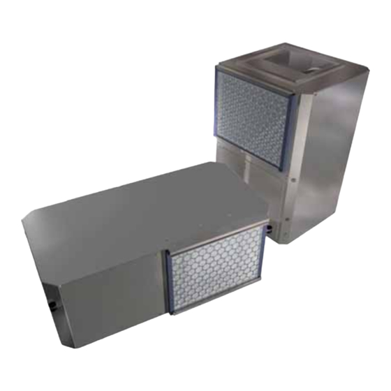
Summary of Contents for Trane Axiom GEHB
- Page 1 Installation Operation Maintenance Axiom GEHB Water-Source Heat Pump GEHB-SVX01A-EN 3000-2465-02...
-
Page 3: Table Of Contents
The manual should be read carefully before installation. Unit installation and service should be in accordance with procedures noted in this manual to achieve normal and liable unit operation by experienced technicians authorized by Trane. It’s not the aim of this manual to cover all unit differences or occurrence of problems during installation. -
Page 4: Nomenclature
Nomenclature 12 13 14 15 Digits 1&2 GE=Gerneral efficiency Digit 3 H=Horizontal configuration Digit 4 B=Develop sequence Digits 5&6&7 Nominal size Digit 8 Voltage 6=220-240V/50Hz/1Ph for 009,012,015,018 9=380-450V/50Hz/3Ph for 024,030,036,042,048,060 Digit 9 Remoter 1=Wire controller(as standard) 2=Wire controller and wireless controller Digit 10 Controller M=Microcomputer controller... -
Page 5: Unit Dimensions
Unit Dimensions Model 009-012 1020 015-024 1168 1140 030-036 1270 1243.5 608.5 042-060 1475 1442 Figure 1 Unit Dimensions... -
Page 6: Receiving And Storage
Receiving and storage purpose, if else, a service should be on Field receiving the way. Inspect the unit carefully for possible freight damage. Should any damage revealed, a report should be submitted Field storage to the carrier for compensation. Check This unit is designed for indoor use. -
Page 7: Preinstallation
Preinstallation must be reserved for convenient Hanging unit service and fluent ventilation. Minimum Balance the unit weight center for clearance required for vertical unit safety before unit hanging. Refer to service and ventilation is shown in Table 1 and Figure 2 for unit gross Figure 4. -
Page 8: Installation And Checklist
Installation and checklist Installation checklist 7 . C o n d e n s a t e h o s e a n d t r a p recommended to attenuate noise and installation should be firmly placed for decrease static pressure loss due to Installation completed, check with fluent drainage. - Page 9 Installation and checklist lieu of filter rack, duct opening panel Return duct opening panel can be equally sealed. Duct flange is A return duct opening frame is added used for field piping ease, as shown in to the return opening for horizontal unit Figure 8.
- Page 10 Installation and checklist Step 5 Install filter frame on the right Alternate return installation Alternate supply installation If unit received is not as required with Follow procedures hereafter to easily return configuration, follow procedures alternate air supply, back supply to left hereafter to easily alternate return supply as shown.
- Page 11 Installation and checklist Step 5 Remove fan assemblies Step 7 Fix the fan assemblies F o u r - s p e e d m o t o r w i r i n g color Motor High speed High Wire color Blue Black...
- Page 12 Installation and checklist Concealed installation for Condensate drain S u p p l y / r e t u r n h o s e horizontal unit connection Hose with female thread size of 1/2” Following procedures hereafter for is used for drain discharge. Install S u p p l y / r e t u r n f l e x i b l e h o s e i s horizontal unit installation.
- Page 13 Trane has a variety of composition of pumps, which connect directly to loss minimum. of joint components for the best supply/return hose.
-
Page 14: Field Wiring
Trane shoulder no 5.High voltage wire is connected firmly Thread the communication shield liability for installation performed by and reliably to the control box thru wire thru the reserved hole on the unqualified personnel. -
Page 15: Control Panel And
Control panel and remoter operation guide Figure 18 Control panel and remoter Note 1.For description only. Difference may occur from actual controller. 2.Unit will do null when no option is provided for a function. - Page 16 Control panel and remoter operation guide Fuctions LCD display 1 Power Button 1 Temperature Display Power on/off shift. Display temperature set value 2 Temperature Set/Change Button 2 Time&Timer Display This button set is for temperature/time setting. Tempera- Display current time. Display a cycle of power-on ture range 15-30 time, power-off time and current time when press query button.
-
Page 17: Wiring Diagram
Wiring diagram... - Page 18 Wiring diagram...
- Page 19 Wiring diagram...
- Page 20 Wiring diagram...
-
Page 21: Start-Up And Commissioning
Start-up and operation Preliminary checks before Unit start-up procedures start-up Maximize controller temperature set Before proceeding with a start-up of value. individual units, the following steps S e t s y s t e m a s C O O L , f a n a s should be verified: AUTO on temperature controller. -
Page 22: Maintenance
Maintenance In open system water filter of sixty Preventive Maintenance holes or more per spuare centimeter Maintenance on the unit is simplified must be installed in case of foreign w i t h t h e f o l l o w i n g p r e v e n t i v e materials entrance to heat exchanger. -
Page 23: Troubleshooting
Troubleshooting Problem Heating Cooling Cause Correction No response to Main power off Check fuses any thermostat Defective control transformer Replace setting Broken or loose connection Repair Defective thermostat Replace Unit short Thermostat improperly located Relocate Defective compressor overload Replace cycles Heat anticipator setting Adjust B l o w e r r u n s... - Page 24 A business of American Standard Companies www.trane.com Since Trane has a policy of continuous product improvement, it reserves the right to change specifications For more information, contact your local district and design without notice. The installation and servicing of the equipment referred in this manual should be office done by qualified, experienced technicians.


