Table of Contents
Advertisement
Quick Links
Installation, Operation, and Maintenance
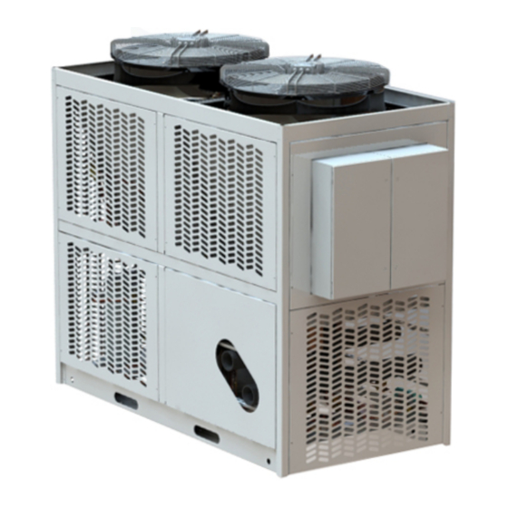
Thermafit™ Air-to-Water Heat Pump
Model AXM
Only qualified personnel should install and service the equipment. The installation, starting up, and servicing of heating, ventilating, and air-conditioning equipment
can be hazardous and requires specific knowledge and training. Improperly installed, adjusted or altered equipment by an unqualified person could result in death or
serious injury. When working on the equipment, observe all precautions in the literature and on the tags, stickers, and labels that are attached to the equipment.
August 2022
SAFETY WARNING
ARTC-SVX006A-EN
Advertisement
Table of Contents

Related Manuals for Trane Arctic Thermafit AXM


Summary of Contents for Trane Arctic Thermafit AXM
- Page 1 Installation, Operation, and Maintenance Thermafit™ Air-to-Water Heat Pump Model AXM SAFETY WARNING Only qualified personnel should install and service the equipment. The installation, starting up, and servicing of heating, ventilating, and air-conditioning equipment can be hazardous and requires specific knowledge and training. Improperly installed, adjusted or altered equipment by an unqualified person could result in death or serious injury.
- Page 2 (HCFCs). Not all refrigerants containing these compounds bump cap, fall protection, electrical PPE and arc have the same potential impact to the environment. Trane flash clothing). ALWAYS refer to appropriate advocates the responsible handling of all refrigerants-...
- Page 3 Follow EHS Policies! This document and the information in it are the property of Trane, and may not be used or reproduced in whole or in Failure to follow instructions below could result in part without written permission. Trane reserves the right to death or serious injury.
-
Page 4: Table Of Contents
Table of Contents Model Number Descriptions ....6 Module Control Wiring ....18 Model Number and Coding. - Page 5 Table of Contents Maintain Glycol Level ....36 Annually ......50 Prevent Freezing.
-
Page 6: Model Number Descriptions
Heat Pump Reference Data. Refer to the Trane model number and serial number of the heat pump nameplate on each module in the installed unit for the modules in question. -
Page 7: Heat Pump Description
This manual provides relevant data to properly operate, construction and operation of the equipment. The heat maintain, and troubleshoot the Trane AXM air-to-water pump modules arrive fully charged with refrigerant. As modular heat pump. Operator and maintenance personnel... - Page 8 Heat Pump Description Load Heat Exchanger Each module contains a brazed plate heat exchanger constructed with SAE Grade 316 stainless steel corrugated channel plates with copper filler material between each plate. The filler material forms a brazed joint at every contact point on the plates creating complex channels. This allows fluid to come into close proximity of the cold refrigerant, separated only by channel plates, thereby efficiently cooling the fluid to the required temperature.
-
Page 9: Pre-Installation
Pre-Installation Preparation for Initial Startup 6. Inspect all fuses and overload settings to ensure they conform to specifications. After the system is completely installed with all wires 7. Inspect all refrigerant pressures for each module to connected and all piping securely coupled, the heat pump ensure no refrigerant has been lost. - Page 10 Check the box if there are any customer-supplied devices connected to the heat pump wiring. ☐ List devices: ______________________________________________________________________________________ Check the box if there are any Trane remote devices connected to the heat pump wiring. ☐ Check the box if voltage drops are detected.
-
Page 11: Startup
Note: To view the software version, from the home screen, press the software button on the System Control screen. Startup As part of a continuous commitment to quality, initial startup of this Heat Pump must be done by Trane. ARTC-SVX006A-EN... -
Page 12: Installation Mechanical
Any damage must be properly after installation. reported to the motor carrier and Trane within five days of The customer must notify Trane during the sales process receipt of the shipment. -
Page 13: Handling Of The Modules
Failure to adhere to these long-term storage requirements • Current transformer secondaries (current mode) may void the Trane warranty. Any component that is must be shorted or connected to a burden at all damaged or inoperable due to improper storage may have times. -
Page 14: Service Access
Even a walls, fences, overhanging roof eaves, or is located in a pit partial overhang of an eave or awning can trap hot air and (sub-level site), contact Trane to discuss potential impact significantly degrade heat pump performance. on equipment performance. -
Page 15: Rigging, Lifting, And Moving The Heat
Installation Mechanical Rigging, Lifting, and Moving the • Rig, lift, and move by strapping and lifting using a properly configured floor jack or fork lift or by overhead Heat Pump means. The air-to-water modular heat pump can be delivered to the •... -
Page 16: Mounting Rails
Installation Mechanical Mounting Rails Consult submittal drawings to confirm dimensions. See Figure 3, p. The heat pump must be positioned on a firm, level surface. All of the modules arrive with labels on the electrical and When modules are installed onto structural steel rails, the control panel. -
Page 17: Installation Piping
Installation Piping Install Piping and External the pipes. A 40-mesh screen strainer must be installed in each water/liquid system piping inlet for proper filtration an Components protection of the heat exchangers. The following figure provides a recommended installation of components. Proper support of piping and pipe hangers must consider the weight of the piping as well as the water weight inside Figure 4. -
Page 18: Installation Electrical
Installation Electrical Connecting Module Power and voltage connections at the mounting socket. No further adjustment should be required. Control Wires Power Interlock Switch Connections are made at the primary module, which typically contains the power distribution panel . Some air-to-water heat pump systems are optionally equipped with a panel-mounted disconnect switch installed WARNING on the outside of the power distribution panel. -
Page 19: Operating Principles
Operating Principles Minimum Fluid Volume and A typical HVAC system has a cooling requirement in the summer and shoulder seasons and a heating requirement Avoidance of Short Loops in the winter and shoulder seasons. A modular air-source heat pump system provides an efficient means to address Adequate system fluid volume is an important system varying cooling and heating demands. -
Page 20: Operating Procedures
Operating Procedures Operator Interface Panel-Mounted Disconnect Switch Some heat pump systems are optionally equipped with a The modular heat pump units, whether they are composed panel-mounted disconnect switch installed on the outside of a single module or up to 10 modules, are automated of the power distribution panel (or on each module’s systems that use a main electrical panel to monitor, report, electrical and control panel if the heat pump has power... -
Page 21: Module Electrical And Control
Operating Procedures Module Electrical and Control Panel fuses and breakers, compressor switches, and the microprocessor controller. See the following figure. Each module has its own electrical and control panel that distributes electricity to individual components. It also has Figure 6. Module electrical and control panel Electronic Control 4. -
Page 22: Operating The Microprocessor
The basic level, ‘user,’ does not require a password. The higher access levels are the technician (‘tech’) and administrator (‘admin’) levels that can only be accessed by Trane technical personnel. Contact Trane Operating the Microprocessor technical support regarding the possibility of any potential issues involving the higher-level functions. -
Page 23: Touchscreen Interface Panel
Operating Procedures about the heat pump, as well as the status of critical The interface panel displays information on its touchscreen parameters within each module of the Heat Pump. whenever specific combinations and sequences of keys and buttons are pressed by the operator (See following Touchscreen Interface Panel figure). -
Page 24: Interface Menu Structure
Operating Procedures Interface Menu Structure Key interface screens are organized according to system, primary module, and secondary modules functions. See Figure 10, p. Figure 10. Interface navigation scheme Home Screen Features Figure 11. HMI home screen ARTC-SVX006A-EN... -
Page 25: Hmi Functions
Operating Procedures HMI Functions Figure 12. User logging screen 1 - HMI Software Version Calls up the pop-up window Project Name: HMI software project name; Software Version.: HMI software version. Consists of 4 two-digit numbers. First 2 numbers: major and minor software revision. -
Page 26: Modules Layout Screen
Operating Procedures • OFF by Switch. System is off by software switch. It can be turned on / off either from Home Screen (button marked 11 on figure 1), which all users have access to. It can also be turned on / off from BAS (Building 13 - Date/Time Automation System). -
Page 27: Active Alarms Screen
Operating Procedures Table 3. Module status conditions (continued) Compressor 1 is running; Compressor 2 is not Compressor 1 is running; Compressor 2 is in alarm running Fan bank running Fan bank not running Fan bank in alarm Active Alarms Screen Figure 15. -
Page 28: Alarm History
Operating Procedures Time Reset PLC This column is the date-time stamp indicating exactly when This button is – used to reset ‘Active’ alarms in the PLC, so the alarm occurred. they could be further acknowledged / reset on the HMI. Only alarms which alarm condition is false can be reset in Check / Uncheck All the PLC otherwise Reset PLC will have no effect on it. -
Page 29: Modules Overview Screens
Operating Procedures State For example: High Pressure switch alarm records before filter applied. This is the same as ‘State’ for active alarms. Description This is the same as ‘Description’ for active alarms. Alarms Filtering High Pressure switch alarm records after filter applied. ‘State Filter’... -
Page 30: Overview Module
Operating Procedures Table 4. The overview screens Primary Overview Module Screen Secondary Overview Module Screen Primary and Secondary Overview Circuit Screen Overview Module or cooling loads. It also acts as a Supervisor when communicating with secondary modules and defines Module En/Dis how many modules need to run its compressors in order to satisfy heating or cooling controlled Pressing this button enables or disables a module. -
Page 31: Overview Circuits
Operating Procedures EX Valve a. Primary Status states 3 or 4 will cause all the modules to run in Stand-alone mode. These failing Indicates the position of electronic expansion valve, if conditions are false at normal primary/secondary installed. operation. Rvrs Valve b. -
Page 32: Analog Inputs
Operating Procedures Data is collected by sensors as either analog or digital signals and displayed on the IO Status screens. When the module screen is displayed, pressing the I/O button displays the I/O menu. The I/O menu is comprised of three screens. When in the I/ O menu switching between I/O screens is made by the means of respective buttons. -
Page 33: Analog Outputs
Operating Procedures control inside control panel is required either heating (for If common power supply protection module is used for the cold environment) or cooling (for hot environment). heat pump, its failure will affect each module. In such a case this DI is optional for secondary module. AI12 These inputs indicate Liquid Line Temperature Circuit 1. -
Page 34: Expansion Io Screen
Operating Procedures DO1, DO2, DO6 • An alarm that shuts down and locks out the entire module. Fans 1, 2, 3. This digital output is used to turn fans of Fan Bank 2 on and off. DO11 Panel Heater / Fan (optional) This is the digital output is used when temperature control inside control panel is required (identical to AI11). -
Page 35: Operator Tasks
Operating Procedures 1. Trending variables instantaneous values according to WARNING cursor position. Current cursor timestamps are Hazardous Voltage! displayed as well. Failure to disconnect power before servicing could 2. Text box to select viewing time span. It’s used for result in death or serious injury. zooming in on trends time axis. -
Page 36: Water Quality Guidelines
This action sends a of the Heat Pump. command to the controller in each module’s compressors to discontinue electrical current to that Note: Trane will not validate the heat pump warranty if the component. proper water/glycol mixture composition and quality is not maintained. -
Page 37: Prevent Freezing
As a glycol-based freeze prevention is using the appropriate concentration of fluid cools below the solution’s freezing point, ice crystals glycol. Trane does not warranty any component that fails begin to form, and the remaining solution becomes more due to freezing. - Page 38 Operating Procedures Storage Provisions normal conditions, propylene glycol sets to a glass-like solid, rather than freezing. The heat pump controls are designed for storage in The addition of glycol to water yields a solution with a ambient temperatures from -20 °F (-29 °C) to 145 °F (63 ° freezing point below that of water.
-
Page 39: Controls Interface
Controls Interface Microprocessor Control System Operator Control and Monitoring Each system is provided with a touchscreen interface panel AXM air-to-water modular heat pump models employ a that is used to turn the heat pump on and off, adjust set Carel c.pCO all-digital data control system to control and points, clear alarms, and perform detailed set-up of the report key system settings and indicators. -
Page 40: Electrical Controls
Controls Interface Electrical Controls Figure 21. Power distribution panel The AXM heat pump is provided with controls and indicators to monitor the electrical activity and notify operators if problems arise. Figure 22. Module electrical and control panel Panel Disconnect Some heat pump systems are optionally equipped with a panel-mounted disconnect switch installed on the outside of the power distribution panel (or on each module’s electrical and control panel if the heat pump has power... -
Page 41: Refrigeration Controls
Controls Interface NOTICE Superheat is factory-set for around 12 °F (-11 °C). Close the valve to increase superheat. To accurately read Proof of Flow Switch! superheat, install a temperature sensor at the load heat Failure to provide flow switches or jumping-out of exchanger outlet. - Page 42 90 psi “cut out” (corresponding to 50 °F (10 °C)) and a 105 psi “cut in” (corresponding to 40 °F (4.4 °C)) cut in. For NOTICE any other water/glycol mixture, contact Trane technical support for proper set points. Equipment Damage!
-
Page 43: Sequence Of Operations
Sequence of Operations This manual describes a typical air-to-water heat pump chiller demand. Both options can be enabled/disabled system with few, if any, optional components or devices individually. When Time Rotation is enabled, Rotation attached. Period has to expire before Lead is rotated. Demand Rotation rotates Lead when the last compressor is staged off. - Page 44 Sequence of Operations 18. To balance that out, only limited number of modules is heating mode. Besides, unbalanced heating capacity allowed to run in Defrost Mode at the same time can be compensated by running additional modules in compared against number of modules running in Heating Mode as driven by increased Heating Demand.
-
Page 45: Heat Pump Performance Data
Heat Pump Performance Data This manual uses a typical 60-ton air-cooled heat pump a heat pump’s precise electrical and refrigerant data can be consisting of two modules with brazed plate load heat found on the heat pump model nameplate. See “Model exchangers for example purposes. - Page 46 Heat Pump Performance Data Table 9. Typical AXM air-to-water heat pump selection of two 30 ton modules (continued) Input Power at Full Load 73.97 kW Chiller MCA 68.0 A Compressors 55.3 A Chiller MOCP 100.0 A Fans 4.5 A Electrical performance per power supply Number of power supplies Chiller FLA 119.7 A...
-
Page 47: Maintenance Procedures
The primary goal of preventive maintenance is to avoid the lubrication fluids. consequences of equipment failure. Trane chillers are • Prudent maintenance strategy will anticipate and designed for ease of access with a premium placed on... -
Page 48: Weekly
Maintenance Procedures Table 10. Recommended heat pump service intervals Frequency Task Visually inspect the heat pump Daily Log pressure and temperatures Daily Inspect touchscreen interface panel for alarm history Weekly Clean strainers on the inlet water pipe Monthly Check the compressor oil level sight glass Monthly Confirm the glycol concentration Monthly... -
Page 49: Quarterly
Maintenance Procedures NOTICE Important: Extended operation with suction pressures below 80 psi is a clear sign of insufficient Equipment Damage! refrigerant charge, refrigeration obstruction, or Failure to remove moisture from system could cause valve closed. This can cause extensive corrosion within the chiller/heater components, and damage to a compressor. -
Page 50: Annually
Maintenance Procedures a. Verify that the pressure controls (low pressure and WARNING high pressure switches) are “cutting in” and “cutting Refrigerant under High Pressure! out” at the appropriate pressures. Failure to follow instructions below could result in an b. Verify refrigerant charge by recording the superheat explosion which could result in death or serious and sub-cooling temperatures. -
Page 51: Critical Cleaning Tasks
Replace the gasket and end cap and tighten coupling collar securely. On multiple module heat pumps, Trane provides service isolation valves on each load heat exchanger to isolate 9. Ensure the water/glycol make-up system is operational... -
Page 52: Compressor Tasks
Verify that no power is build-up. Trane recommends using straight tap water present with a voltmeter. except in extreme cases. (Take extra precautions by covering electrical components with plastic bags, etc.) -
Page 53: Controller Tasks
Maintenance Procedures 1. Position the compressor into the heat pump and align 11. Observe and document the operating pressures of the the mounting holes. Apply anti-seize compound to the newly installed compressor. It is advised that the four mounting bolts, washers, and nuts before expansion valve superheat adjustment be checked. -
Page 54: Heat Pump Troubleshooting
Isolation Fault detection is recognizing that a problem has occurred, Trane manufactures heat pump with embedded fault even if the root cause is not yet known. Fault isolation is the detection and diagnostics in each module’s controller that... - Page 55 Heat Pump Troubleshooting Table 11. Interface panel diagnostic code key (continued) ALARM RESET ACTION EVD Driver B Alarm Auto Warning EVD 2 offline Auto Warning EVD 2 System Alarm Auto Warning EVD 2 Driver A Alarm Auto Warning EVD 2 Driver B Alarm Auto Warning Evaporator Freezing Alarm...
-
Page 56: Compressor Diagnostic Codes
Compressor Diagnostic Codes KRIWAN Flash Codes The KRIWAN flash code allows for a quick and easy status Compressors used in Trane air-to water heat pumps use display and troubleshooting. solid state protection and have PTC (Positive Temperature Coefficient) internal sensors with an avalanching The error code consists of a red and orange pulse resistance in the event of high temperatures. -
Page 57: Phase Monitor Protection
Heat Pump Troubleshooting Table 12. KRIWAN flash codes Error Category Flashing Sequence (red LED) Flashing Sequence (orange Error Status LED) Nominal response temperature of motor was exceeded Switch off due to blocked rotor Time delay active after motor Motor temperature temperature default Sensor fault motor PTC Time delay active after blocked rotor... - Page 58 Heat Pump Troubleshooting 1. Symptom: Compressor will not start Possible Causes Potential Solutions High pressure event has occurred; Check fan settings and functionality; High pressure switch open Check obstructed coils; Check pressure switch functionality Allow motor to cool and reset; High amp load/floodback; Compressor Compressor overload opened operating outside of operating envelope No power to module...
- Page 59 Heat Pump Troubleshooting 5. Symptom: Compressor loses oil Possible Causes Potential Solutions Compressor short cycling Adjust proper control settings for Min. ON/OFF runtime Check compressor superheat. Superheat at the compressor suction should be Liquid refrigerant approximately 12° F 6. Symptom: Low refrigeration suction pressure Possible Causes Potential Solutions Lack of refrigerant...
- Page 60 Heat Pump Troubleshooting 8. Symptom: Low refrigerant discharge pressure Possible Causes Potential Solutions Low suction pressure See low refrigeration suction pressure Incorrect fan control settings Check fan settings 9. Symptom: High refrigerant discharge pressure Possible Causes Potential Solutions System overcharged with refrigerant (especially at low ambient temperature in Remove excess refrigerant heating mode) Dirty tube and fin surface...
- Page 61 Heat Pump Troubleshooting 13. Symptom: No low voltage (24 Vac) Possible Causes Potential Solutions Transformer primary side fuse open Check fuse prong contact points; Replace fuse Replace transformer Transformer defective No primary voltage on transformer Check breakers, fuses; Check power supply specifications 14.
-
Page 62: Logical Flow Diagrams
Logical Flow Diagrams The following section presents the simplified logical flow worldwide market. The high voltage configuration for a heat block diagrams for the principal systems in the AXM air-to- pump module is listed on each module’s name plate. The water modular heat pump. - Page 63 Logical Flow Diagrams Figure 25. Control logical flow ExV A Relay A ExV A Relay B EVX1 Dig Outputs EVX2 EVX1 Dig Outputs EVX2 Power Dig 1 An 2 Dig 2 Power Dig 1 An 2 Dig 2 Power Supply An 1 Inputs Input Input...
-
Page 64: Refrigeration Logical Flow
Logical Flow Diagrams Refrigeration Logical Flow AXM heat pump uses two independent refrigeration circuits per module using vapor injected scroll compressors. See below figure. Figure 26. Product schematic - cooling mode Figure 27. Product schematic - heating mode ARTC-SVX006A-EN... -
Page 65: Acronyms And Abbreviations
Appendix A. Acronyms and Abbreviations All acronyms and abbreviations used in this manual, on the Table 14. Acronyms and abbreviations (continued) heat pump controllers, and on module indicators and Expansion Item gauges are listed in the following tables. Electromagnetic Interference Extended Performance Compressor Acronym List EvapFl... - Page 66 Acronyms and Abbreviations Table 14. Acronyms and abbreviations (continued) Table 14. Acronyms and abbreviations (continued) Expansion Expansion Item Item Locked Rotor Amperes Rotation revolutions per minute minute Maximum Redundant Pump Minimum second Monday Saturday NEMA National Electrical Manufacturers Association Saturated Discharge Temperature NFPA National Fire Protection Association Set Point...
-
Page 67: Request For Initial Startup
Trane at least 10 working days prior As part of a continuous commitment to quality, initial startup of this heat pump by a factory-certified technician may be to the scheduled initial startup date. -
Page 68: Initial Startup Agreement
Request for Initial Startup Initial Startup Agreement startup technician. Payment for an aborted startup will be forfeited. Rescheduled initial startups are subject to any additional costs that may have been incurred by the technician. An approved purchase order or payment in By signing this form, you agree the heat pump is ready for advance will be required to reschedule an aborted initial initial startup. - Page 69 Notes ARTC-SVX006A-EN...
- Page 70 Notes ARTC-SVX006A-EN...
- Page 71 Notes ARTC-SVX006A-EN...
- Page 72 For more information, please visit www.arcticchillergroup.com Trane has a policy of continuous product and product data improvements and reserves the right to change design and specifications without notice. We are committed to using environmentally conscious print practices.