Table of Contents
Advertisement
Quick Links
Installation, Operation, and Maintenance
Water Source Heat Pump
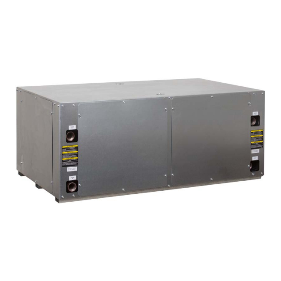
Axiom™ Water-to-Water — EXW
5 to 20 Tons — 60 Hz
Only qualified personnel should install and service the equipment. The installation, starting up, and servicing of
heating, ventilating, and air-conditioning equipment can be hazardous and requires specific knowledge and training.
Improperly installed, adjusted or altered equipment by an unqualified person could result in death or serious injury.
When working on the equipment, observe all precautions in the literature and on the tags, stickers, and labels that are
attached to the equipment.
June 2022
SAFETY WARNING
WSHP-SVX02E-EN
Advertisement
Table of Contents

Related Manuals for Trane Axiom EXW Series


Summary of Contents for Trane Axiom EXW Series
- Page 1 Installation, Operation, and Maintenance Water Source Heat Pump Axiom™ Water-to-Water — EXW 5 to 20 Tons — 60 Hz SAFETY WARNING Only qualified personnel should install and service the equipment. The installation, starting up, and servicing of heating, ventilating, and air-conditioning equipment can be hazardous and requires specific knowledge and training. Improperly installed, adjusted or altered equipment by an unqualified person could result in death or serious injury.
- Page 2 CFCs and HCFCs such as saturated or unsaturated HFCs and HCFCs. Important Responsible Refrigerant Practices Trane believes that responsible refrigerant practices are important to the environment, our customers, and the air conditioning industry. All technicians who handle refrigerants must be certified according to local rules. For...
- Page 3 WARNING This document and the information in it are the property of Personal Protective Equipment (PPE) Trane, and may not be used or reproduced in whole or in Required! part without written permission. Trane reserves the right to revise this publication at any time, and to make changes Failure to wear proper PPE for the job being undertaken could result in death or serious injury.
-
Page 4: Table Of Contents
Table of Contents General Information ..... 5 Jobsite Inspection ....5 Jobsite Storage . -
Page 5: General Information
General Information located internal to the cabinet on the 5-ton through 20- ton equipment. WARNING • After assuring that charge has been retained, reinstall Fiberglass Wool! the caps to assure that refrigerant leakage does not Exposition to glass wool fibers without all necessary occur. - Page 6 Deluxe 24V Controls The Deluxe 24V control design will incorporate a microprocessor-based control board. The Trane microprocessor board is factory wired to a terminal strip to provide all necessary terminals for field connection. The...
-
Page 7: Model Number Description
Model Number Description Digits 1, 2, 3 — Unit Configuration EXW = Water to Water Heat Pump Digit 4 — Development Sequence E = R-410A Digits 5, 6, 7 — Nominal Size (Tons) 060 = 5 Tons 120 = 10 Tons 240 = 20 Tons Digit 8 —... -
Page 8: Dimensions And Clearances
Dimensions and Clearances WARNING Improper Unit Lift! Failure to properly lift unit in a LEVEL position could result in unit dropping and possibly crushing operator/ technician which could result in death or serious injury, and equipment or property-only damage. Test lift unit approximately 24 inches (61 cm) to verify proper center of gravity lift point. - Page 9 Dimensions and Clearances Figure 2. EXW*060 SOURCE SIDE HEAT EXCHANGER LOAD SIDE HEAT EXCHANGER [17] [508] CONTROL BOX [1016] ISO VIEW TOP VIEW CONTROL BOX ACCESS HIGH VOLTAGE Ø1 1/8 [28.6] [559] 24 VOLT Ø7/8 [22.2] 10 1/8 [257] 4 1/8 [105] 2 3/8 [25]...
- Page 10 Dimensions and Clearances Figure 3. EXW*120 SOURCE SIDE HEAT EXCHANGER WATER OUT WATER OUT LOAD SIDE HEAT EXCHANGER WATER IN WATER IN [50.8] [50.8] [25.4] [25.4] [838.2] CONTROL BOX [1473.1] ISO VIEW TOP VIEW CONTROL BOX ACCESS 24 VOLT Ø7/8 [22.2] [610] HIGH VOLTAGE Ø1 1/8 [28.6]...
- Page 11 Dimensions and Clearances Figure 4. EXW*240 SOURCE SIDE LOAD SIDE HEAT EXCHANGER HEAT EXCHANGER 3 1/8 [78.0] 1 1/4 [30.4] 31 3/8 [797.0] CONTROL BOX 81 1/2 [2069.9] ISO VIEW TOP VIEW CONTROL BOX ACCESS HIGH VOLTAGE Ø1 1/8 [28.6] 24 VOLT [762.0] 21 3/4...
-
Page 12: Installation
Installation General Installation Checks WARNING The checklist below is a summary of the steps required to Improper Unit Lift! successfully install a unit. This checklist is intended to acquaint the installing personnel with procedures Failure to properly lift unit in a LEVEL position could required in the installation process. -
Page 13: Cleaning And Flushing The Water Loop
Installation Figure 5. Water connection Cleaning and Flushing the Water Loop water being dumped). Continue blow down until the water leaving the drain runs clear, but not less than 2 After the piping system is complete, the flexible hose hours. connectors should be doubled back to complete the water 6. -
Page 14: Using Antifreeze
Installation Using Antifreeze Field Installed Power Wiring In areas of the country where entering water temperatures drop below 45°F or where piping is being run through WARNING areas subject to freezing, the loop must be freeze Hazardous Voltage! protected by using an approved antifreeze solution to prevent the earth loop water from freezing inside the heat Failure to disconnect power before servicing could exchanger. -
Page 15: Control Power Transformer
Installation Controls Using 24 Vac Figure 7. Unit power wiring Before installing any wire, refer to the electrical access UNIT POWER WIRING locations on the unit dimensions on Dimensions and 3 PHASE POWER SUPPLY Clearances chapter. 1TB1 • Ensure that the AC control wiring between the controls and the unit’s termination point does not exceed three --------------------- --------------- L3... -
Page 16: Electrical
Electrical Table 6. Electrical performance EXW* units Maximum Minimum Maximum Minimum Overcurrent VOLTS-AC/ Utilization Utilization Total Unit Comp Comp No. of Circuit Protective Model No. HZ/PH Voltage Voltage RLA (ea) LRA (ea) Compres. Ampacity Device 208/60/1 26.3 26.3 134.0 32.88 230/60/1 26.3 26.3... -
Page 17: Pre-Start
Pre-Start Pre-Start-up Checklist Before energizing the unit, the following system devices must be checked: – Is the high voltage power supply correct and in accordance with the nameplate ratings? – Is the field wiring and circuit protection the correct size? –... -
Page 18: Unit Start-Up
Unit Start-up Start-up with the system controls is included below: 1. Set the system control to the cooling mode of operation. 2. Turn on the circulation pumps. The compressor should NOT run. 3. Reduce the temperature control setting until the compressor, reversing valve and solenoid valve are energized. -
Page 19: Operating Data
Operating Data Table 7. Operating data for cooling EXW*060 Source Load Compressor Water Suction Flow Water Temp Discharge Unit Model EWT °F WPD FT Temp Rise EWT °F Flow GPM WPD FT Pressure Drop °F Pressure PSIG °F PSIG 12 - 16 11 - 14 84 - 97 179 - 228... - Page 20 Operating Data Table 8. Operating data for heating EWX*060 Source Load Compressor Water Suction Discharge Flow Temp Drop Flow Water Temp Pressure Pressure Unit Model EWT °F WPD FT °F EWT °F WPD FT Rise °F PSIG PSIG 7 - 9 9 - 12 58 - 67 149 - 190...
- Page 21 Operating Data Table 9. Operating data for cooling EWX*120 Source Load Compressor Water Water Discharge Temp Rise Flow Temp Drop Suction Pressure Unit Model EWT °F Flow GPM WPD FT EWT °F WPD FT °F Pressure PSIG PSIG 13 - 16 11 - 15 89 - 103 182 - 231...
- Page 22 Operating Data Table 10. Operating data for heating EXW*120 Source Load Compressor Water Suction Discharge Water Temp Flow Temp Rise Pressure Pressure Unit Model EWT °F Flow GPM WPD FT Drop °F °F WPD FT °F PSIG PSIG 10.3 7 - 9 9 - 12 57 - 65 256 - 326...
- Page 23 Operating Data Table 11. Operating data for cooling EXW*240 Source Load Compressor Water Water Suction Flow Temp Rise Temp Pressure Discharge Unit Model °F WPD FT °F EWT °F Flow GPM WPD FT Drop°F PSIG Pressure PSIG 12 - 15 11 - 13 87 - 100 180 - 229...
- Page 24 Operating Data Table 12. Operating data for heating EWX*240 Source Load Compressor Suction Water Temp Flow Water Temp Pressure Discharge Unit Model EWT °F Flow GPM WPD FT Drop °F °F Rise °F PSIG Pressure PSIG 6 - 8 8 - 10 54 - 62 233 - 297 13.1...
-
Page 25: Start-Up Checklist And Log
Operating Data Table 13. Water volume Unit Size Water Volume Cubic Inches Water Volume Cubic Feet Water Volume Gallons (U.S) EXW*060 359.6 0.21 1.57 EXW*120 719.2 0.42 3.14 EXW*240 2079.0 1.20 8.98 Note: The above water volume is the total unit water volume ( Source + Load), divide the above volume by 2 to obtain source or load side volumes individually. Flow Checks For the operating temperature drop (heating) and rise (cooling), refer to Table 7 through Table 12 for the proper... -
Page 26: Maintenance
Maintenance Preventive Maintenance It should be noted that the water quality should be checked periodically. Refer to the table below. Maintenance on the unit is simplified with the following Table 14. Water quality table preventive suggestions: Scaling WARNING Calcium and magnesium (total hardness) Less than 350 ppm Hazardous Voltage! Corrosion Failure to disconnect power before servicing could... -
Page 27: Troubleshooting
Troubleshooting • Verify that the unit is receiving electric supply power. WARNING • Ensure that the fuses in the fused disconnect (field installed) are intact. Hazardous Service Procedures! After completing the preliminary checks, inspect the unit Failure to follow all precautions in this manual and on for other obvious problems such as leaking connection, the tags, stickers, and labels could result in death or broken or disconnected wires, etc. - Page 28 Troubleshooting Table 15. Troubleshooting checklist (continued) Problem Heating Cooling Cause Correction Trash in heat exchanger Backflush Low water flow Increase GPM High head pressure Overcharge of refrigerant Decrease charge Non-condensable in system Evacuate and recharge by weight Water too hot Decrease temperature Undercharged Locate leak, repair and recharge...
-
Page 29: Wiring
INPUT. TERMINAL 1TB2-7 AND 1TB2-8 AND/OR DASHED DEVICE OUTLINES INDICATE COMPONENTS PROVIDED BY THE FIELD. SOLID LINES INDICATE WIRING BY THE TRANE CO. ISOLATED GENERAL ALARM CONTACTS. CONTACTS CLOSE WHEN CONTROL 1U1 AND 1U2 GOES INTO MANUAL LOCKOUT MODE. NUMBERS ALONG THE LEFT SIDE OF THE CONTACTS RATED FOR CLASS 2 24V. - Page 30 INPUT. TERMINAL 1TB2-7 AND 1TB2-8 AND/OR DASHED DEVICE OUTLINES INDICATE COMPONENTS PROVIDED BY THE FIELD. SOLID LINES INDICATE WIRING BY THE TRANE CO. ISOLATED GENERAL ALARM CONTACTS. CONTACTS CLOSE WHEN CONTROL 1U1 AND 1U2 GOES INTO MANUAL LOCKOUT MODE. NUMBERS ALONG THE LEFT SIDE OF THE CONTACTS RATED FOR CLASS 2 24V.
-
Page 31: Warranty
The optional extended warranty is a second through fifth year warranty. The time starts at the end of standard 1- year coverage through the fifth year. These extended warranties apply only to new equipment installed in domestic Trane sales territories and must be ordered prior to start-up. WSHP-SVX02E-EN... - Page 32 For more information, please visit trane.com or tranetechnologies.com. Trane has a policy of continuous product and product data improvement and reserves the right to change design and specifications without notice. We are committed to using environmentally conscious print practices.