Table of Contents
Advertisement
Quick Links
Electromagnetic Locks
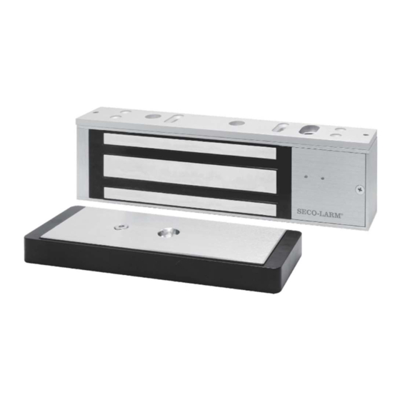
Installation Manual
E-941SA-1K2DPSQ shown
Model***
E-941Sx-600DPSQ*
E-941Sx-1K2DPSQ*
E-941Sx-600PQ
†
E-941Sx-1K2PQ
†
E-941Sx-1K2PD
‡
*
With status LED, bond sensor, and door position sensor
**Holding force has not been verified by UL
MOV surge protection
Adjustable mounting bracket
Complete mounting hardware for typical installations
"L" bracket and "Z" brackets available for easy mounting
Detachable faceplate
12/24VDC selectable
NOTES:
UL294 Indoor use
The power for the E-941Sx series is to be provided by a Listed (UL294 or UL603) Class 2 Power Supply.
The E-941Sx series is intended to be used as an access control system accessory which is installed in
accordance with the manufacturer's installation and operation instructions, ANSI/NFPA 70 and the local
authority having jurisdiction.
The minimum permissible wire size to be used shall not be less than 22AWG
Holding Force**
600-lb (272kg)
1,200-lb (545kg)
600-lb (272kg)
1,200-lb (545kg)
1,200-lb (545kg)
†
With status LED and bond sensor
***"x" is the variable for product color "A" for aluminum, "B" for black, and "D" for dark bronze
Material
Anodized aluminum
Anodized aluminum
Anodized aluminum
Anodized aluminum
Anodized aluminum
‡
With status LED, bond sensor, and timer
Advertisement
Table of Contents

Related Manuals for SECO-LARM E-941S-600DPSQ Series


Summary of Contents for SECO-LARM E-941S-600DPSQ Series
- Page 1 Electromagnetic Locks Installation Manual E-941SA-1K2DPSQ shown Model*** Holding Force** Material E-941Sx-600DPSQ* 600-lb (272kg) Anodized aluminum E-941Sx-1K2DPSQ* 1,200-lb (545kg) Anodized aluminum E-941Sx-600PQ † 600-lb (272kg) Anodized aluminum E-941Sx-1K2PQ † 1,200-lb (545kg) Anodized aluminum E-941Sx-1K2PD ‡ 1,200-lb (545kg) Anodized aluminum † ‡ With status LED, bond sensor, and door position sensor With status LED and bond sensor With status LED, bond sensor, and timer...
-
Page 2: Parts List
SECO-LARM Electromagnetic Locks Parts List 1x Electromagnet 1x Armature plate 2x Short self-tapping screws 1x Armature screw 2x Steel washers 1x Rubber washer 4x Long self-tapping screws 1x Sexnut bolt 2x Guide pins 1x Door spacer 2x Hex-head mounting screws... -
Page 3: Installation Applications
3. The most suitable mounting location for the electromagnetic lock may require the use of additional SECO-LARM accessories such as Z-brackets, L-brackets, and/or spacer plates. Please see the diagram on page 3 to decide if a particular application requires any mounting accessories. -
Page 4: Installation
SECO-LARM Electromagnetic Locks Installation 2. Close the door. Find a mounting location 1. Fold the mounting template along the dotted line to form a 90-degree angle. on the door frame near the upper free- moving corner of the door, or as close as possible to the upper corner of the door frame opposite the hinges. - Page 5 SECO-LARM Electromagnetic Locks Installation (Continued) 7. Put a rubber washer between the two 8. Tighten the armature screw enough so that metal washers and place them over the the armature plate can withstand a break-in armature screw between the armature attempt, but loose enough so that the plate and the armature plate holder.
- Page 6 SECO-LARM Electromagnetic Locks Installation (Continued) 12. Remove the cover from the front of the 13. Push the electromagnet against the electromagnet. Run the power leads mounting plate so the electromagnet ends through the large cable access hole. are flush with the ends of the mounting plate.
-
Page 7: Wiring Diagram
SECO-LARM Electromagnetic Locks Wiring Diagram Circuit Board Control Device – N.O. – Power N.C. Supply 12/24 VDC Voltage = 12VDC jumpers = 24VDC NOTES Connect switching devices like push-to-exit switches between the power source and the positive terminal of the lock. Connecting them to the negative terminal may cause a delay in unlocking. -
Page 8: Troubleshooting
IMPORTANT: Users and installers of this product are responsible for ensuring that the installation and configuration of this product complies with all national, state, and local laws and codes. SECO-LARM will not be held responsible for the use of this product in violation of any current laws or codes.